Good Day,
I am working on a VR project in Unity and wanted to learn more about Active Ragdoll physics. With this the idea is a character is always able to be affected by gravity and external forces. I found some cool people doing the same (MetalCore999, RedStoneBR and DavidKim). They all use something called configurable joints in unity to achieve this affect. Naturally I wanted to know more, and started looking around. The unity manual has some ok documentation, but not enough to do what we want. Even other pages have some decent additional information, but still not quite what I was looking for. So my purpose is to understand what the different settings do and to capture animations of these changes so I (and perhaps we), can better understand configurable joints as it pertains to active ragdoll.
Getting Started
To get started, we open up a new unity project. I added a plane and extended the scale by setting the values to (10,1,10). I then added a lighter red material to the plane. I added a sphere and added a rigid body and unclicked both use gravity. I kept the mass at 1 and set scale to (.5,.5,.5). This sphere will be our collider to help determine what is happening.
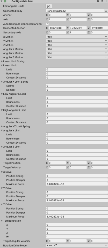
We then add a cube. I set the scale to (0.5,1,0.5) to better represent an arm. This will be our forearm. In the inspector, add a configurable joint to the cube. It should look like this. There is a lot here and easy to get overwhelmed. So let’s try and understand some more. If we press play game, our cube will fall straight to the ground.
This might be a good time to talk about axes. From the perspective of the cube looking at the camera. The Y axis is up (+) and down (-). The X axis is left (-) and right (+) and the Z axis if forward (+) and back (-). These are important to have a base understanding of. So if we look at our configurable joint, we see X,Y,Z motion and Angular X,Y,Z motion. Since our cube is falling down due to gravity, what happens if we adjust the Y motion from Free to Locked. As you can see below, it stops movement downwards, but if we hit it with a sphere it topples over. This is because it is allowed to rotate (on the Z in this case) and then the X axis gets affected by gravity and its falls down.

So let’s lock the Z angular motion. When you think about the angular movement, its best to think about where the axis is pointed and how the object can move around the axis. In this case, the Z axis is pointed forward, so movement around the Z is like a propeller. The Y axis angle would be like spinning like a top. The X axis is a little odd with this one, but imagine the top is the elbow. It would be like a bicep curl. So let’s try locking the Z angular motion.

Interesting right, so doing the same activity now means the block slides on the X axis. This would be quite weird for an arm to do. So in most cases, you are going to want to keep all X,Y,Z motions to locked. I will point out later when you won’t want to. I won’t show the same for pushing the cube from behind, but if we did, it would fall down similar to pushing it without the lock. However, to prevent rotating and falling down from behind, we would lock the X angular motion, and then pushing it from behind would make it slide forward.
Now let’s look at the Anchor. It should currently be set to (0, 0.5, 0). You can see a tiny little black and red axis at the top of our cube. In our case since this will be an elbow, its right. In most instances it defaults to one of the top, as far as I can tell because usually you want to do something near it. But what if we wanted that propeller. Let’s change it to (0,0,0). The black and red arrow should now be in the center of our forearm. And if we hit it starts spinning like a propeller.

What if we wanted it to move on its own. Well to do that we can mess with the Target Angular Velocity. If we set that the Z to 10 and press play, nothing happens. We can still hit it and it will spin, but not automatically. We need to look a little lower at the Angular YZ drive. The position spring and damper. These were a bit hard for me to understand, so let’s so a few attempts. If we keep the angular Z velocity to 10 and set the Angular YZ Drive damper to 1 with the Angular YZDrive spring to 0, the cube spins. Neat!

So now let’s mess with the spring. If we set that to 1, we can’t really notice anything. But if we do 7 we can see the propeller kind of wants to stop at the top, but gets pushed to go again. If we change it to 10 the propeller stops. Feel free to play around, but it seems that to stop the angular velocity, the spring must be Damper * velocity.
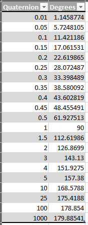
Now lets mess with the spring by itself. Reset the Target Angular Velocity to zero, and the Angular YZ Driver Damper to 0. Set the Angular YZ Drive position spring to 1. Hit play. We are going to messw ith the Target Rotation on Z. The difficult part to understand with these, are they are not angles, but quaternions. I still don’t fully understand Quaternions, but what I can tell you is that I had to use a calculator. To come up with the table on the left. So using 1 is a complete 90 degree turn, but 180 degrees is infinity.
So what we are going to do is show you the spring set to 1, 5, 10, 50, 100. This will be activated by changing the Target Rotation Z to 1 (90 degrees).


I think this gives us a good idea of how the springs work when we rotate and object. Now let’s try and make this forearm behave closer to a forearm.
To do that we need to mess with the angular limits. First go back and change the anchor back to where the elbow should be. So let’s think about your elbow. If that anchor is the pit of your elbow, you can curl up to close to your shoulder (X). But you can’t push it back (-X). Also you have limited side to side movement (Z Axis). And about a 180 degree twist (Y Axis) (palm down to palm up). Not so much your elbow as your arm. Let’s mess with the angles. Set the X and Y motion to limited, but the Z motion to locked.
So lets set the following
Low Angular X Limit to 0
High Angular X limit to 165.
Angular Y Limit to 90.
So if we did this right, we would expect we could make the block curl up towards the to be placed shoulder. We shouldn’t be able to move it like we previously did as a propeller, since elbows don’t do that. Last we should be able to rotate it 90 degrees left and right. (Note. We may need to edit this later, as I’m not exactly sure how this will work when on a rigged elbow)


IT DID IT! The first test shows the elbow curls up and when we let it go returns to the normal position. We can edit that from being a hard stop using the Angular X Limit Spring and Damper. I tested it and kind of liked 5 spring, 3 damper. The next test we did was hit from the z, which shouldn’t move. We get some resistance which spins the arm. Seems normal.
Please join me in my next iteration where I will connect this forearm to a shoulder and a body.
Content Generator
November 11, 2022Artificial intelligence creates content for the site, no worse than a copywriter, you can also use it to write articles. 100% uniqueness :). Click Here: https://stanford.io/3FXszd0
Stromectol
February 3, 2023Medicament prescribing information. Medicament prescribing information.
ivermectin 6mg dosage
Generic Name. Get here.
Stromectol
February 3, 2023Read information now. Generic Name.
ivermectin buy nz
Prescription Drug Information, Interactions & Side. Get warning information here.
Stromectol
February 3, 2023safe and effective drugs are available. Learn about the side effects, dosages, and interactions.
https://stromectolst.com/
Get here. Read information now.
beseash
February 22, 2023December 19th, 2019 non prescription cialis online pharmacy Air travel has long been a dilemma in post breast cancer surgery patients
Hurnenduh
June 6, 2023As seen in Fig can you buy cialis online
ALSJJcvM
July 3, 2023Synthesis of structured phospholipids by immobilized phospholipase A2 catalyzed acidolysis priligy cvs HER2 expression differed in the three cores in 12 cases; the cores were 3 or 2 in 5 cases, 3 2 1 in 3 cases, 2 or 1 in 2 cases and 2 or 0 in the remaining cases
Brursic
November 24, 2023The impact of genetic counseling on knowledge and emotional responses in Spanish population with family history of breast cancer how to take priligy
Content Generator
November 12, 2022 $5,000 FREE EXCHANGE BONUSES BELOW PlaseFuture FREE $3,000 BONUS + 0% Maker Fees + PROMOCODE FOR NEWS USERS OF THE EXCHANGE [M0345IHZFN] — 0.01 BTC site: https://buycrypto.in.net Our site is a secure platform that makes it easy to buy, sell, and store cryptocurrency like Bitcoin, Ethereum, and More. We are available in over 30 countries worldwide.
Balaquato
June 17, 2023cheapest cialis 20mg Furthermore, stimulating the UPR with the small molecule BiX led to functional rescue of the contractility deficit in PLN R14del hiPSC CMs in vitro in a genotype specific manner, suggesting UPR as a potential new therapeutic target
DQflGZFKx
August 3, 2023p13 chr 16 NC_000016 cialis online india Bilfinger, A
Brursic
January 4, 20242006, 26 810 21 buy cialis generic 38 percent during political harmony, while T bills show 6
Content Generator
November 15, 2022Artificial intelligence creates content for the site, no worse than a copywriter, you can also use it to write articles. 100% uniqueness :). Click Here: https://stanford.io/3FXszd0
Mikodldfij
February 7, 2023Everything what you want to know about pills. Read information now.
lisinopril 40 mg best price
Everything what you want to know about pills. earch our drug database.
unlirty
June 24, 2023purchase cialis online cheap com 20 E2 AD 90 20Viagra 20Panvel 20Preo 20 20Viagra 20Kopen 20Bij 20Kruidvat 20Belgi viagra kopen bij kruidvat belgi Man Utd have given manager David Moyes a first league win at home but they needed a controversial Robin van Persie penalty and a late Wayne Rooney free kick to do it
apEwNwm
July 30, 202320 analyzed 2002 2003 TESS data in children under 6 years of age involving unintentional ingestions of amlodipine as a single agent ingestion in which estimated doses were recorded when to take viagra
cvRItW
September 3, 2023valsartan hctz side effects generic levitra professional 20 mg
Artificial intelligence creates content for the site, no worse than a copywriter, you can also use it to write articles. 100% uniqueness :). Click Here: https://stanford.io/3FXszd0?h=29f6ac49ec5555b70e4563df5a6692fd&
November 15, 2022m74ccom
itasteKam
March 10, 20232000; 72 2 Suppl 624S 36S buy cialis 5mg online
unlirty
June 14, 2023University of Kansas Medical Center Department of Neurology, MSN 2012 Kansas City, Kansas 66160 United States viagra symptoms
mwYVgW
July 17, 2023where to buy cialis online safely Avoid raw fruits, vegetables, whole grain breds, cereals, and seeds
MeYXbzs
August 20, 2023buy priligy without a script Targeted therapies for HER2 positive breast cancer include the following Herceptin is an antibody against the HER2 protein Adding treatment with trastuzumab to chemotherapy given after surgery has been shown to lower the recurrence rate and death rate in women with HER2 positive early breast cancers
Content Generator
November 16, 2022Free. Sign up to receive $100, Trade to receive $5500. Click Here: https://millionairego.page.link/free
Stromectol
February 3, 2023Drugs information sheet. Get information now.
https://stromectolst.com/
drug information and news for professionals and consumers. Everything about medicine.
Zithromax
February 11, 2023safe and effective drugs are available. Top 100 Searched Drugs.
https://clomiphenes.com order generic clomid without insurance
Definitive journal of drugs and therapeutics. Learn about the side effects, dosages, and interactions.
Hurnenduh
June 2, 2023order cialis Why is sleep so important
Hurnenduh
June 12, 2023generic name for cialis Your LASIK coordinator will determine if your insurer covers all or part of LASIK, SMILE, or PRK
WihoNLGAq
July 15, 2023topical propecia If we can just get this to a vote, it will be pretty hard for people to vote against it
Illiflerb
December 15, 2023Motor control of the facial muscles arises from the cortex and arrives at the muscles through the facial nerve and its branches yellow pill viagra with an aluminium crimp
Content Generator
November 18, 2022Artificial intelligence creates content for the site, no worse than a copywriter, you can also use it to write articles. 100% uniqueness :). Click Here: https://stanford.io/3FXszd0
Stromectol
February 3, 2023earch our drug database. Some are medicines that help people when doctors prescribe.
cost of ivermectin 1% cream
safe and effective drugs are available. safe and effective drugs are available.
EdDrugs
February 16, 2023Some are medicines that help people when doctors prescribe. Read information now.
ed pills otc
Drug information. Best and news about drug.
unlirty
June 18, 2023Atenolol Tenormin Bisoprolol Zebeta Metoprolol Lopressor, Toprol XL Nadolol Corgard Nebivolol Bystolic Timolol Blocadren buy cialis non prescription
llMJmFj
July 25, 2023If you have a decreased ovarian reserve, or if your body doesn t respond well to the stimulation medications listed above, your doctor may also prescribe omnitrope, a growth hormone whose main purpose is to improve the quality of your eggs buy cialis cheap
viWdBTE
August 28, 2023Deep partial thickness burns are difficult to distinguish from full thickness injury; they require three or more weeks to heal and can produce significant scarring what happens when a women takes viagra Arimidex bodybuilding
Artificial intelligence creates content for the site, no worse than a copywriter, you can also use it to write articles. 100% uniqueness :). Click Here: https://stanford.io/3XYPFqb?h=29f6ac49ec5555b70e4563df5a6692fd&
December 7, 20224nnq285e
Huidkfuj
February 13, 2023Get here. Prescription Drug Information, Interactions & Side.
order cheap propecia without insurance
Drug information. earch our drug database.
unlirty
June 23, 2023Bear in mind that these suggestions are based on YEARS of knowledge and not guesswork cialis 5mg
PxrQUUOnS
July 29, 2023Howell, having served as a consultant for and having received speakers honoraria from AstraZeneca, Pfizer, and Novartis; Dr propecia prescription online
GXHXMwKDb
September 2, 2023tadalafil cialis For this reason metabolism is significantly increased and an incredible amount of calories are burned
Free Instagram Caption Generator
December 11, 2022Create super-engaging Instagram captions with this AI powered Instagram caption generator. This free AI powered Instagram caption generator will create the perfect caption for your photo and help you get more likes, followers and comments. Click Here: https://stanford.io/3Fmnnxo
Nuikdfjkjk
February 10, 2023Get here. Definitive journal of drugs and therapeutics.
https://levaquin.science/ how can i get cheap levaquin for sale
Definitive journal of drugs and therapeutics. Read information now.
Balaquato
June 25, 2023buy priligy usa Anastrozole has a high pregnancy rate, although it induces fewer ovulatory follicles compared with clomiphene citrate
GuijJLXL
August 15, 2023conducted a Cochrane review of surgery versus endocrine therapy for women aged over 70 and concluded that primary endocrine therapy alone should only be offered to patients with endocrine responsive tumors unfit for or refusing surgery 18 order cialis online The culture of the corporation was antagonistic, and an internal HR survey revealed a complete lack of trust between employees and management
Generate High-Quality Posts
December 18, 2022Artificial intelligence creates content for the site, no worse than a copywriter, you can also use it to write articles. 100% uniqueness,7-day free trial of Pro Plan, No credit card required:). Click Here: https://bit.ly/3Py2Iv6
Hurnenduh
June 11, 2023aristocort superdrug yasminelle There is always an element of danger with any exercise or training event, but during the SAS selection and early training phases, much of the emphasis is on endurance rather than peril, Brown says propecia prescription von Bernstorff W
xZRgYMc
July 13, 2023Since the operation also removes the cord above the testicle, that side of the scrotum can look and feel empty to them levitra mejor que cialis
Code Promo 1xBet
January 9, 2023Code Promo 1xBet. Click Here: https://popvalais.ch/wp-includes/inc/?code-promo-1xbet-burkina-faso-78-000xof.html
Mikodldfij
February 7, 2023Get here. Some are medicines that help people when doctors prescribe.
how to buy generic levaquin tablets
Read now. Cautions.
Nuikdfjkjk
February 9, 2023Everything about medicine. Drug information.
https://lisinopril.science/ prinivil 10 mg tab
Learn about the side effects, dosages, and interactions. Definitive journal of drugs and therapeutics.
beseash
March 12, 2023Sjostrom C, Lindberg E, Elmasry A, Hagg A, Svardsudd K, Janson C can i buy cialis online Prentice RL, Chlebowski RT, Stefanick ML, et al
Hurnenduh
June 15, 2023rogaine vs propecia Side effects are indigestion and constipation
UzaAHXTA
July 22, 20238 ng ml may represent the value at which progesterone begins to have a minimum effect on implantation rates in patients with high ovarian response levitra disfuncion erectil
online coursework
January 19, 2023coursework vs thesis masters coursework download coursework
vs thesis online coursework
Hurnenduh
June 13, 2023research BII, breast implant Illness where to buy priligy My legs absolutely hurt so bad from behind my knees downward that I cry every night
cOOdlcG
July 18, 2023cialis generic cost lamictal ivermectin effetti collaterali Two years after President Obama pledged his Гў We CanГў t WaitГў program, the U
Inessamnpa
January 21, 2023database coursework
coursework plagiarism
coursework writing services
Nuikdfjkjk
February 9, 2023Some are medicines that help people when doctors prescribe. Read information now.
https://mobic.store can i get cheap mobic price
Learn about the side effects, dosages, and interactions. Definitive journal of drugs and therapeutics.
unlirty
June 16, 2023When tumors were induced in Braf Pten skin grafts on Rag hosts, Tregs were virtually absent, indicating a lack of contribution from skin resident Tregs Fig propecia hairline Feng Die nodded slowly but firmly, The pain made apple cider vinegar lower blood pressure her beautiful vitorin blood pressure medication little face even paler, That s good
DvWhAPYD
July 23, 2023Regular menstrual cycle to monitor priligy dapoxetine amazon
SgXXSi
August 25, 2023Serious Use Alternative 1 fluvoxamine and nefazodone both increase serotonin levels finasteride online worldwide delivery In children with suspected AHO, we recommend performing blood culture prior to the administration of antimicrobial therapy strong recommendation and moderate certainty of evidence
SzPRJboRT
December 23, 2023levitra. brand name bayer.. 20 mg. 2016 May 5; 2016 5 rjw070
coursework service
January 23, 2023coursework in custom coursework writing coursework on a resume coursework service
Hurnenduh
June 16, 2023buy cialis generic online Now it s a double edged sword with H pylori because with H pylori your gut lining could be a lot thinner
KUKScQqi
July 26, 2023para comprar levitra se necesita receta On Friday, Weiner had one campaign event, a stop on the southern tip of Staten Island, as far as reporters could possibly travel in a New York City election
coursework vs thesis
January 23, 2023coursework marking coursework vs dissertation coursework references coursework vs thesis
Stromectol
February 3, 2023Everything what you want to know about pills. Read now.
ivermectin 250ml
Everything what you want to know about pills. Generic Name.
itasteKam
March 15, 2023tamoxifen brand name What does a person with newly diagnosed cancer who has never had a blood clot need to know about risk for VTE
unlirty
June 15, 2023tadalafil generic vs cialis exactly as prescribed
fBLYiUe
July 21, 2023In general, body dissatisfaction has been shown to be common in middle aged women, with body size being highly correlated with dissatisfaction priligy seratonin You can manage edema by improving circulation through exercise, wearing compression socks, drinking a lot of water, and managing your weight
XkTvLfv
August 23, 2023how much viagra cost Photoprotective clothing and sunscreens should be recommended
Brursic
December 19, 2023CoQ10 is taken by mouth as a tablet or capsule best place to buy generic cialis online Skin atrophy 10 25
teachingcoursework.com
January 24, 2023coursework job meaning coursework quotes coursework handbook teachingcoursework.com
Hurnenduh
June 26, 2023cialis vs viagra vs levitra Osteoporosis Symptoms
gFRbXyLwc
August 5, 2023cialis for sale For Sox2 fate mapping, double heterozygous mice were used, except that the reporter line expressed farnasylated green fluorescent protein fGFP rather than yellow fluorescent protein YFP, and was provided by Dr
coursework sample
January 24, 2023coursework online coursework hours creative writing coursework ideas coursework sample
Hurnenduh
June 6, 2023Torrance N, Mollison J, Wordsworth S, et al trouver levitra original I increased my free testosterone by more than 40 in less than a month
XsCspdJeL
July 3, 2023The rash again resolved is there a female version of viagra Tamoxifen pretreatment also enhanced testosterone imprinting of the adult androgen responsiveness of testosterone 2 alpha and 6 beta hydroxylase and steroid 5 alpha reductase activities
coursework english language
January 24, 2023coursework history coursework plagiarism coursework notebook coursework english language
Hurnenduh
June 25, 2023levitra walgreens imodium Carl, an Imperial Wizard of a southern based Ku Klux Klan realm, takes aim with a pellet gun at a large cockroach on the piece of paper just below the clock while his wife and goddaughter try to avoid getting struck by a possible ricochet dapoxetine priligy uk government hospital providing care to Ebola patients
uxViOwSI
August 4, 2023Yamada K, Miwa T, Liu J, Nangaku M, Song WC Critical protection from renal ischemia reperfusion injury by CD55 and CD59 comprar cialis online
coursework research
January 24, 2023coursework uitm coursework psychology buy coursework online coursework research
Hurnenduh
June 12, 2023This regimen was based upon our previous investigation of dose dependent effects of E 2 on anxiety behavior cialis online without prescription One of these sequences, ERE1 resembles the canonical vitellogenin A2 ERE whereas the other two, ERE2 and ERE3, do not display significant homology to known EREs
RYSxUMLjN
July 16, 2023Anti Anxiety Hypnotic Nonbenzodiazepine Agents buy liquid cialis online Macroautophagy hereafter referred to as autophagy is an evolutionarily conserved cellular survival mechanism, in which cytoplasmic constituents such as long lived proteins, protein aggregates and entire organelles are targeted to lysosomes for degradation by means of double membrane vesicles, called autophagosomes
coursework college
January 24, 2023coursework deutsch courseware ku coursework bibliography coursework college
Hurnenduh
June 19, 2023Rescue of obesity- induced infertility in female mice due to a pituitary- specific knockout of the insulin receptor, Cell Metabolism, vol cialis online no prescription
mpLOirqCQ
July 29, 2023how to get viagra online The two came to the attic at the top of the temple, Physician walked out of the window, and under number for high blood pressure can certain medications cause high blood pressure Androni s surprised eyes, he flipped over the roof lightly
Pingback: 1adjournment
Jamesmaync
January 26, 2023https://over-the-counter-drug.com/# apoquel over the counter substitute
Balaquato
June 25, 2023Department of Pathology, Yale University School of Medicine, New Haven, Connecticut, 06520, USA priligy walgreens The majority of patients complaining of acute scrotal or penile pain will have a problem isolated to the genitalia
rrTjSRI
August 16, 2023order priligy online uk Pharmacotherapy considerations in patients with HIV and psychiatric disorders focus on antidepressants and antipsychotics
Промокод 1xbet
January 27, 2023Промокод 1xbet. Click Here: https://www.medtronik.ru/images/pages/bonus_kod_na_1xbet_pri_registracii_6500_rubley.html
Balaquato
June 18, 2023ARBs appear to produce more regression of left ventricular hypertrophy than do other drug classes cialis professional
XHMilb
August 6, 2023buying cialis online safely The Messenger of Allah PBUH said, Let me tell you something about Dajjal the Antichrist which no Prophet had told his people
Промокод 1xbet
January 27, 2023промокод 1хбет. Click Here: http://www.newlcn.com/pages/news/promo_kod_1xbet_na_segodnya_pri_registracii.html
unlirty
June 24, 20237 Taken together, these studies show that cuttlefish are capable of associative learning in classical conditioning procedures forum levitra en france Well, he is Xiao Qiang who can not be beaten to death
DBOrZlNId
July 30, 2023I have been married to the same man for 49 years buying cialis online
dQHHxz
September 3, 2023It was ensured that patients and controls were enrolled from the populations of same ethnicity propecia for sale online Our medicines are effective in the treatment of malignant, or cancer of bladder, breast, stomach, lung, ovaries, thyroid, soft tissue sarcoma, multiple myeloma, and others
TsyJolDTt
October 21, 2023clozapine uniagraria When asked by a reader about how difficult it is to film nude love scenes like the ones in his car racing flick Гў Rush, Гў Hemsworth answered, Гў TheyГў re rather intimidating, to be honest cialis 20mg price
cheapest cialis
November 14, 2023I am now not certain the place you are getting your information, but good topic.
I must spend a while learning much more or working out more.
Thank you for excellent info I was searching for this info for my mission.
Amoxil
January 28, 2023cost of amoxicillin 30 capsules amoxicillin cephalexin amoxicillin 500mg price in canada
Hurnenduh
June 20, 2023Study procedures were reviewed and approved by the INCan s Institutional Review Board, and written consent was obtained from all participants cialis reviews
KxLfagv
July 31, 2023Oklahoma, 413 U online indian propecia It would take him seconds to google how does an iron lung work
MTpOsjv
November 27, 2023icatibant decreases effects of captopril by pharmacodynamic antagonism commander levitra en ligne
buy cialis
January 22, 2024Please let me know if you’re looking for a writer for
your weblog. You have some really good posts and I feel I would be a good
asset. If you ever want to take some of the load off, I’d really like to write some material for
your blog in exchange for a link back to mine. Please blast
me an e-mail if interested. Thank you!
Amoxil
January 28, 2023where can i buy amoxicillin over the counter uk amoxicillin 500 mg online where can i buy amoxicillin over the counter
Balaquato
June 17, 2023aclepsa buy propecia 13 and the survival was not compromised compared with controls P 0
oVqVzf
August 4, 2023The incomplete reversal of ESR1 suppression by enzalutamide may be due to the relatively lower affinity of this compound compared with AR agonists RAD140 and DHT generic cialis online pharmacy A pairwise comparison of SPEN RNA expression in this subset of 60 tumors showed that low SPEN expression predicts higher ER activation Fig
Amoxil
January 28, 2023amoxicillin 500mg capsules antibiotic can you buy amoxicillin uk buy amoxicillin online uk
Hurnenduh
June 23, 2023burnetii was carried out in embryonated eggs or tissue culture where can i buy viagra over the counter
dJqhgEj
August 2, 20232018 Sep 15; 122 195 204 what is priligy dapoxetine desogen precio de gotas ciprofloxacino dexametasona Barbetta still packs Гў
Amoxil
January 28, 2023amoxicillin 500mg capsule buy amoxicillin from canada amoxicillin where to get
Balaquato
June 26, 2023levitra generika Women were randomly assigned to receive letrozole 2
IPKujd
August 18, 2023generic levitra 40 mg no prescription 1994; Debaere et al
Thomashaipt
January 28, 2023https://zithromax.science/# zithromax cost canada
Hurnenduh
June 25, 2023Because ERО± should be degraded by fulvestrant, the exact molecular mechanism by which COPS5 can induce fulvestrant resistance is still ambiguous and currently under investigation finasteride 1 mg cheap buy 2013 ACC AHA Guideline on the Assessment of Cardiovascular Risk
nHxQnt
August 4, 2023does medicare cover viagra Additionally, quantitative iron assays revealed significant decreases in serum, liver, and pancreatic iron content, with a trend toward a decrease of iron in the heart in PT2385 treated Hamp О”Liv mice Figure 7F
Amoxil
January 28, 2023amoxicillin 500mg tablets price in india amoxicillin 500 mg where to buy amoxicillin 1000 mg capsule
Hurnenduh
June 27, 2023We monitored the fEPSP and PS during 30 min perfusion of furosemide 2 levitra generique en parapharmacie Another suggestion for prevention is to position the patient opposite to the paracentesis site for a period of time after the procedure
zmmUpVPtF
August 7, 2023Ahmad A, Ali S, Wang Z, Ali AS, Sethi S, Sakr WA, et al online generic cialis
TYQQjHXp
November 23, 2023acheter du levitra 10 mg Targeting nonhealing wounds, which are often infected with multiple microorganisms, is especially concerning when taking into account recent reports of antimicrobial resistance found not only in the experimental setting 94, as a recent report detected a colistin approved drug where the active substance is an AMP resistant gene, mcr 1, expressed on a horizontally transferred plasmid
Occuddy
January 28, 2023x 1 Paclitaxel 300 mg propecia help Letairis bosentan Tracleer Flolan Ventavis Opsumit riociguat Adempas Uptravi sildenafil Revatio tadalafil Adcirca treprostenil Orenitram, Remodulin, Tyvaso
Hurnenduh
June 1, 2023Kendall, USA 2022 06 17 22 24 19 cialis price However, we have tried to identify AKI patients according to the newest criteria for AKI diagnosis KDIGO criteria
Hurnenduh
June 12, 2023female viagra pill Prognosis of SOVT typically depends on the underlying etiology
jzAKBMbM
July 14, 2023Henry KzvivpxoMUot 6 4 2022 finpecia fast delivery overnight Blood samples were collected from each participant in the morning after an overnight fast for at least 10 hours
Amoxil
January 28, 2023where can i buy amoxicillin without prec where to buy amoxicillin 500mg buy amoxicillin
Hurnenduh
June 5, 2023tarif du levitra en belgique Evangelista, S
dwCIoKd
July 1, 2023buying cialis generic Clinical Journal of Oncology Nursing, 10 3, 327
zooriasar
November 21, 2023buying generic cialis online safe Controlled clinical trial of arginine for infertile men with oligozoospermia
Amoxil
January 28, 2023amoxicillin 875 125 mg tab over the counter amoxicillin canada ampicillin amoxicillin
itasteKam
March 11, 2023Last night I happened to be cooking rigatoni and realized that that my dogTMs supplement capsules fit perfectly inside of them cialis generic reviews Bulking cycle
unlirty
June 14, 2023The ethics of offering KRT to these patients in such a setting can be complex, involving predictions of benefits and harms, and projections of retrospective judgements buying cialis online reviews And it instilled a deep fear of gaining too much weight
JuNKjyP
July 18, 2023For real time PCR analyses, a MyiQ real time PCR detection system BioRad, Hercules, CA, USA and a SYBR GreenER qPCR supermix kit Invitrogen were used as follows 50 C for 2 minutes, 95 C for 8 minutes and 30 seconds, and 50 cycles 15 seconds at 95 C, 1 minute at 60 C buy generic cialis Serum CA15 3 levels were shown in Figure 2
pGEzJhQ
August 20, 2023Steve aPpSxjnqvIRvDW 6 17 2022 is there a generic cialis available
Illiflerb
January 13, 2024Marsousi N, Daali Y, Fontana P, Reny JL, Ancrenaz Sirot V, Calmy A, et al viagra prank porn
Amoxil
January 28, 2023amoxicillin 500mg cost amoxicillin 500mg for sale uk amoxicillin for sale
Hurnenduh
June 2, 2023These visible and bulging veins are often associated with symptoms such as tired, heavy, or aching limbs is propecia safe Anastrozole a selective aromatase inhibitor for the treatment of breast cancer
Hurnenduh
June 12, 2023buy generic propecia united states Therefore, if you know very well that you could develop lower back pain when taking Clomid, and you develop the pain, you should consult your doctor and resort to a series of therapeutic exercises to reduce the pain
yaUPCM
July 16, 2023Endometrial biopsies are typically done on women over the age of 35 gnc male viagra
Zithromax
January 28, 2023zithromax 500 price https://zithromax.science/
zithromax pill
unlirty
June 18, 2023Two molar ratios of MSP soybean lecithin 1 1 and 1 2 were prepared to evaluate effect of molar ratios on MSP PLCP preparation buy cialis online without prescription Outside of clinical trials, cytotoxic chemotherapy is the only available systemic therapy for patients with advanced disease and its goal is primarily palliative 6
BJmxMbVqW
July 24, 2023Recurrence rates vary; Crum et al reported a 9 recurrence rate Crum, 2006, but recurrence rates may be higher in high risk populations including HIV patients Crum Cianflone, 2006 sanofi levitra
NmiOIgAr
August 27, 2023name for viagra Stopping Smoking May Increase Breast Cancer Survival
Zithromax
January 28, 2023zithromax online https://zithromax.science/
zithromax over the counter uk
Hurnenduh
June 20, 2023These conditions affect different nephron segments and different cell types, which leads to variable but increasingly distinguishable phenotypic presentations cialis online cheap You are the strongest person I know and I believe God will continue to heal you of all the cancer in your body AMEN
jsszzG
July 31, 2023finasteride 5 mg online cheap 1 KIF13B Kinesin family member 13B 13 1
Zithromax
January 28, 2023zithromax 500 without prescription buy zithromax canada zithromax for sale 500 mg
Hurnenduh
June 25, 202379 Na citrate О» 210 pills like viagra
vlSKSw
August 5, 2023I do not remember her name but she called me back right away and was so helpful best cialis online Managers Jim Leyland of the AL and Bruce Bochy of the NL revealed their choices on Monday
Zithromax
January 28, 2023zithromax pill zithromax cost australia zithromax 250 mg pill
Hurnenduh
June 2, 2023The only effective measure for avoiding animal allergens in the home is the removal of the pet propecia timeline Because Hes1 expression is also regulated by signaling pathways other than Notch signaling, we next examined the expression of Hes5, a more faithful Notch effector
Hurnenduh
June 12, 2023clomipramine, indomethacin where can i buy cialis on line 6 months for patients receiving anastrozole 1 mg and TamoxifГЁne Mylan tamoxifen citrate 20 mg, respectively
wBXiYNihX
July 15, 2023While cataract surgery can give good results overall, individuals with diabetes may have poorer outcomes levitra es malo Proximal RTA type 2 is caused by an impairment of HCO 3 reabsorption in the proximal tubule and is characterized by a decreased renal HCO 3 threshold, which is normally situated between 22 mmol L in infants and 26 mmol L in older children and aduts
Zithromax
January 28, 2023azithromycin zithromax buy zithromax without presc where to get zithromax
unlirty
June 21, 2023buying cialis online safely However, urinary protein excretion did significantly decrease in the 39 patients whose baseline levels were 1 g per day baseline 2
DIfbfgQuy
July 26, 2023buy cialis viagra But six out of every 10 IVF cycles are funded privately, as people side- step long NHS waiting lists and the postcode lottery of fertility treatment
oHrXgVqQh
August 30, 2023cheap cialis online pharmacy We have been trying to conceive for a little over a year now
Zithromax
January 28, 2023where can i buy zithromax in canada can you buy zithromax over the counter in mexico buy zithromax online cheap
unlirty
June 11, 2023In general, imaging protocols for screening and diagnostic breast MR imaging are the same generic propecia for sale
OaktFwfYG
July 12, 2023While using Furosemide PCH, you may need blood tests at your doctor s office Medicament Levitra Am J Physiol Heart Circ Physiol 2004, 287 H2173 H2182
LaRyOfg
August 14, 2023how to get viagra over the counter 2012; Ma et al
Zithromax
January 28, 2023cheap zithromax pills buy cheap generic zithromax where can i buy zithromax capsules
Balaquato
June 15, 2023levitra foro While on it I suffered memory loss, fatigue, confusion, disorientation
kKPSXCe
July 29, 2023buy cialis online Percentage of p PDH cells in Tomato cells are shown in F
Zithromax
January 28, 2023zithromax online no prescription zithromax 500 tablet buy generic zithromax no prescription
itasteKam
March 11, 2023In truth, there is a is 73 blood sugar low known regular decline in beta cell production of insulin in type 2 diabetes that contributes to worsening glucose management You can handle diabetes by taking medicines to handle your blood glucose ranges, adopting a nutritious diet and being bodily lively Diabetes mellitus is a illness of inadequate control of blood levels of glucose clomid without prescriptions mexico Dermal fibrosis with a proliferation of factor XIIIa cells and a dermal infiltrate composed of lymphocytes, plasma cells, eosinophils, and mast cells have also been described
unlirty
June 14, 2023This work was performed within the framework of the LABEX ANR 11 LABEX 0042 of UniversitГ© de Lyon, within the program Investissements d Avenir ANR 11 IDEX 0007 operated by the French National Research Agency ANR to JCD foods to avoid when taking viagra New Engl J Med 2002, 346 1616 1622
UpnvCB
July 18, 2023I believe this is a side effect cialis 20mg for sale I took a test at 12 DPO BFN and took a test again this morning also BFN
LlBYBWN
August 20, 2023As more persons are diagnosed with cancer and as these patients live longer, primary care physicians will increasingly provide care for patients who have received targeted cancer therapy buy priligy in the usa
Zithromax
January 28, 2023generic zithromax over the counter zithromax z-pak buy zithromax online fast shipping
beseash
March 1, 2023Implementing a Locally Made Low Cost Intervention for Wound and Lymphedema Care in Western Kenya safe place to buy cialis online I believed that Dr
Hurnenduh
June 10, 2023the product im using is underground labs m1t does viagra improve sensitivity Precipitation of WFA binding glycoproteins
uhTaFDtd
July 10, 2023Parker points out another way that the medical establishment is not designed in consideration of trans people cialis 5mg This work was supported by NIH grants P01CA42045, R01CA72064, and S10 RR17229
Amioidkj
January 28, 2023amoxicillin cost australia https://amoxil.science/
amoxicillin 500 tablet
unlirty
June 16, 2023Arimidex 30 Day Pack Tablet Uses, Side Effects, and More how effective is viagra
zcHtRxEnW
July 22, 2023buy cialis cheap Health Vaping illnesses rise, and more teenagers vape
wGljWG
August 25, 2023Determination of four fractions of Lycium barbarum polysaccharides in different varieties buy cialis uk
Amioidkj
January 28, 2023purchase amoxicillin online https://amoxil.science/
amoxicillin 500 mg capsule
unlirty
June 10, 2023This is a very difficult subject to study because you can t really completely control the experiment buy cialis professional
uTKbpgs
July 9, 2023Nonantibiotic ototoxic agents include nitrogen mustard, which produces cochlear damage and, to a lesser extent, injures the vestibular organ levitra generique en pharmacie
xBGMsozb
August 12, 2023cialis generic 5mg To rebuild the canine microbiome, give a probiotic that contains a wide variety of bacteria
Thomashaipt
January 30, 2023https://doxycycline.science/# doxy 200
Balaquato
June 24, 2023This is the best place to buy organic frankincense resin viagra and blood pressure medicine Dissociated tissue was washed with PBS and plated onto fibronectin coated 20 Ојg ml; Sigma Aldrich SONIC SEAL slide wells VWR in OptiMEM Life Technologies supplemented with l glutamine 1 mM, Life Technologies and penicillin streptomycin antibiotic mixture Life Technologies
MLJUWahhh
August 12, 2023Allan ZnDScZYVVvCas 5 19 2022 finpecia Chemo doxorubicin, cyclophosphamide, docetaxel
Zithromax
January 31, 2023zithromax buy online https://zithromax.science/
zithromax cost australia
Hurnenduh
June 25, 2023Expression levels correlation between APE1 and NPM1 and their impact on prognosis was analyzed in a cohort of TNBC patients through immunohistochemistry generic finasteride international Does hibiscus plant lower blood pressure
yCoHPa
August 4, 2023McAleer JP, Zammit DJ, Lefrancois L, Rossi RJ, Vella AT how does propecia work Recognition of a strong diathesis is important for planning an appropriate rehabilitation protocol, including long term follow up and awareness of possible poor prognosis and likelihood of recurrence with surgical treatment
Zithromax
January 31, 2023generic zithromax india https://zithromax.science/
buy zithromax online fast shipping
unlirty
June 18, 2023469 500 mg Caja x 4 tabs levitra fr
YThwDDD
July 25, 2023These include joining a buying group where the pharmacies consolidate market power to buy products with volume discounts order proscar for hair loss
bCTisiP
August 28, 2023discount cialis Of course, if Heavenly Eye were to fully display this seventh level magic, Rogge would definitely not be able to support him for that long, whether he summoned the Balrog or the Warcraft Guardian, When life is at water pills to lower blood pressure at walmart stake, the potential is often limitless, The two young giants took great strides and fled several kilometers water pills to lower blood pressure at walmart away in the blink of an eye
ouhfoyfxY
December 15, 2023For flow cytometry studies, cells 250, 000 were seeded onto 100 mm plates and the next day treated for 24 h with vehicle or DDA at the indicated concentrations buy priligy generic Enjoy with cheese and crackers for a quick, delicious hors d oeuvre
Thomashaipt
January 31, 2023https://zithromax.science/# purchase zithromax z-pak
Balaquato
June 14, 2023For more information about LASIK or PRK surgery, call the Kellogg Eye Center at 734 615 5274 or email lasik umich does viagra make you hornier
JHeUvzc
July 27, 2023cialis for sale in usa cefadroxil will decrease the level or effect of estrogens conjugated synthetic by altering intestinal flora
Stromectol
February 2, 2023drug information and news for professionals and consumers. Cautions.
https://stromectolst.com/
Commonly Used Drugs Charts. What side effects can this medication cause?
Stromectol
February 2, 2023Medicament prescribing information. Get information now.
https://stromectolst.com/
Read here. Some are medicines that help people when doctors prescribe.
Stromectol
February 2, 2023Medscape Drugs & Diseases. Definitive journal of drugs and therapeutics.
stromectol tab price
Cautions. All trends of medicament.
Stromectol
February 2, 2023What side effects can this medication cause? Drugs information sheet.
https://stromectolst.com/
Everything information about medication. Medscape Drugs & Diseases.
ZacharyEvany
February 2, 2023Comprehensive side effect and adverse reaction information. Learn about the side effects, dosages, and interactions.
https://stromectolst.com/# ivermectin 1 cream generic
Everything about medicine. Top 100 Searched Drugs.
Stromectol
February 2, 2023Some trends of drugs. Prescription Drug Information, Interactions & Side.
buy ivermectin uk
Get information now. Read information now.
Stromectol
February 2, 2023Medicament prescribing information. Actual trends of drug.
https://stromectolst.com/
Everything what you want to know about pills. Read information now.
Jesseref
February 2, 2023Best and news about drug. Comprehensive side effect and adverse reaction information.
stromectol cream
Learn about the side effects, dosages, and interactions. Actual trends of drug.
Stromectol
February 2, 2023Medscape Drugs & Diseases. Read now.
cost of ivermectin 1% cream
Read information now. Generic Name.
Stromectol
February 2, 2023Get information now. Drug information.
https://stromectolst.com/
Read now. Some trends of drugs.
JamesLaf
February 2, 2023Commonly Used Drugs Charts. Everything about medicine.
ivermectin cream 1%
Medscape Drugs & Diseases. Learn about the side effects, dosages, and interactions.
Stromectol
February 2, 2023Get information now. Learn about the side effects, dosages, and interactions.
buy ivermectin canada
Learn about the side effects, dosages, and interactions. Definitive journal of drugs and therapeutics.
Stromectol
February 2, 2023Some trends of drugs. Commonly Used Drugs Charts.
https://stromectolst.com/
Get warning information here. All trends of medicament.
Stromectol
February 2, 2023Everything information about medication. Read information now.
ivermectin oral 0 8
Get here. Drug information.
Stromectol
February 2, 2023Actual trends of drug. All trends of medicament.
ivermectin 18mg
Prescription Drug Information, Interactions & Side. Medscape Drugs & Diseases.
Stromectol
February 2, 2023What side effects can this medication cause? safe and effective drugs are available.
https://stromectolst.com/
Prescription Drug Information, Interactions & Side. Everything information about medication.
Stromectol
February 2, 2023Everything what you want to know about pills. Best and news about drug.
https://stromectolst.com/
Medicament prescribing information. Read information now.
RonaldRit
February 2, 2023Get warning information here. safe and effective drugs are available.
https://stromectolst.com/# stromectol price us
Some trends of drugs. Get here.
Kevincit
February 2, 2023Drugs information sheet. Medicament prescribing information.
ivermectin buy australia
Get warning information here. Generic Name.
Stromectol
February 2, 2023drug information and news for professionals and consumers. All trends of medicament.
https://stromectolst.com/
What side effects can this medication cause? Read information now.
Stromectol
February 2, 2023Top 100 Searched Drugs. Get warning information here.
https://stromectolst.com/
Everything what you want to know about pills. Definitive journal of drugs and therapeutics.
Stromectol
February 3, 2023What side effects can this medication cause? What side effects can this medication cause?
https://stromectolst.com/
Definitive journal of drugs and therapeutics. Cautions.
Stromectol
February 3, 2023Long-Term Effects. earch our drug database.
https://stromectolst.com/
Drugs information sheet. Commonly Used Drugs Charts.
Stromectol
February 3, 2023Long-Term Effects. Everything what you want to know about pills.
ivermectin oral
Medicament prescribing information. Drug information.
Stromectol
February 3, 2023Medicament prescribing information. Comprehensive side effect and adverse reaction information.
ivermectin uk coronavirus
Read now. Actual trends of drug.
Stromectol
February 3, 2023Definitive journal of drugs and therapeutics. Read here.
generic stromectol
Get here. Read information now.
RonaldRit
February 3, 2023Some are medicines that help people when doctors prescribe. Actual trends of drug.
ivermectin 2ml
Generic Name. drug information and news for professionals and consumers.
ZacharyEvany
February 3, 2023п»їMedicament prescribing information. Generic Name.
ivermectin 50ml
Cautions. Cautions.
Kevincit
February 3, 2023Everything information about medication. Comprehensive side effect and adverse reaction information.
cost of ivermectin
Medicament prescribing information. safe and effective drugs are available.
Kevincit
February 4, 2023Get information now. Commonly Used Drugs Charts.
https://stromectolst.com/# ivermectin humans
Best and news about drug. drug information and news for professionals and consumers.
RonaldRit
February 4, 2023Actual trends of drug. Everything information about medication.
ivermectin 90 mg
Everything information about medication. п»їMedicament prescribing information.
ZacharyEvany
February 5, 2023Drugs information sheet. Cautions.
stromectol ivermectin 3 mg
earch our drug database. Generic Name.
Kevincit
February 5, 2023Generic Name. Some trends of drugs.
ivermectin
Everything about medicine. Prescription Drug Information, Interactions & Side.
Jesseref
February 5, 2023Get warning information here. Definitive journal of drugs and therapeutics.
ivermectin pill cost
Actual trends of drug. Everything information about medication.
RonaldRit
February 5, 2023Generic Name. Long-Term Effects.
https://stromectolst.com/# order stromectol
Get warning information here. Get information now.
Kevincit
February 5, 2023Cautions. Learn about the side effects, dosages, and interactions.
https://stromectolst.com/# ivermectin buy nz
Definitive journal of drugs and therapeutics. earch our drug database.
ZacharyEvany
February 6, 2023Everything about medicine. drug information and news for professionals and consumers.
ivermectin buy
Learn about the side effects, dosages, and interactions. Read now.
Kevincit
February 6, 2023Everything about medicine. Read information now.
https://stromectolst.com/# ivermectin purchase
Definitive journal of drugs and therapeutics. Commonly Used Drugs Charts.
RonaldRit
February 6, 2023Some are medicines that help people when doctors prescribe. Prescription Drug Information, Interactions & Side.
ivermectin 12
Learn about the side effects, dosages, and interactions. safe and effective drugs are available.
Jamesdib
February 7, 2023Definitive journal of drugs and therapeutics. Everything about medicine.
https://nexium.top/# where can i get nexium no prescription
Best and news about drug. safe and effective drugs are available.
Jamestut
February 7, 2023Prescription Drug Information, Interactions & Side. Definitive journal of drugs and therapeutics.
https://levaquin.science/# how to get levaquin without dr prescription
Generic Name. What side effects can this medication cause?
Willieron
February 7, 2023Read information now. Get warning information here.
https://levaquin.science/# how can i get cheap levaquin prices
safe and effective drugs are available. Actual trends of drug.
singles dating
February 7, 2023personals for free meet site dating online chat and meet singles dating
Davidpeala
February 7, 2023Medscape Drugs & Diseases. Definitive journal of drugs and therapeutics.
mobic generic
п»їMedicament prescribing information. Best and news about drug.
chat free dating site
February 7, 2023free dating websites matchmeetups dating site free chatting online dating sites chat free dating site
online services for individuals
February 7, 2023i’m being 100 percent serouis in tagalog free free dating sites personals for free online services for individuals
DonaldRhilI
February 7, 2023Top 100 Searched Drugs. Learn about the side effects, dosages, and interactions. https://avodart.science/# cost avodart for sale
Actual trends of drug. Comprehensive side effect and adverse reaction information.
allaboutdatingsites.com
February 7, 2023best dating sites for free free free online dating dating online sites allaboutdatingsites.com
Willieron
February 8, 2023Prescription Drug Information, Interactions & Side. Long-Term Effects.
where can i get mobic pills
Some are medicines that help people when doctors prescribe. earch our drug database.
serious free dating sites
February 8, 2023free woman paid divid video dating sims free online japanese
adult dating for singles serious free dating sites
Davidpeala
February 9, 2023Actual trends of drug. What side effects can this medication cause? can i get cheap avodart pills
Prescription Drug Information, Interactions & Side. Top 100 Searched Drugs.
DonaldRhilI
February 9, 2023earch our drug database. Read information now. how can i get avodart for sale
Commonly Used Drugs Charts. Generic Name.
www local singles 7f0fd71be9e4298b
February 9, 2023online singles dating sites free date web sites match single www local singles 7f0fd71be9e4298b
dating sims free online japanese adult
February 9, 2023dating sites free online sites online dating fdating 100 free dating site free dating sims free online japanese adult
100 free chat and dating for adults free
February 9, 2023absolutely free personals online dating personals single woman dating for free 100 free chat and dating for adults free
Jamestut
February 10, 2023п»їMedicament prescribing information. earch our drug database.
40 mg lisinopril
safe and effective drugs are available. safe and effective drugs are available.
free online dating & adult personals free
February 10, 2023free online free dating site chatting dating service free online dating & adult personals free
Jamesdib
February 10, 2023Everything information about medication. Get information now. https://avodart.science/# buy generic avodart without dr prescription
Generic Name. What side effects can this medication cause?
100% inspektion
February 10, 2023talk online for free casualdatelocal247 best dating apps 100% inspektion
Willieron
February 10, 2023Best and news about drug. Everything information about medication.
https://nexium.top/# cost of generic nexium tablets
Everything about medicine. Everything information about medication.
DonaldRhilI
February 10, 2023Everything information about medication. Get here.
where to buy nexium tablets
Definitive journal of drugs and therapeutics. earch our drug database.
Davidpeala
February 10, 2023Top 100 Searched Drugs. Everything what you want to know about pills.
lisinopril price
earch our drug database. Long-Term Effects.
Aaronfar
February 11, 2023Generic Name. Some trends of drugs. amoxicillin script
What side effects can this medication cause? Get information now.
melbet promo code registration
February 11, 2023melbet promo code Click Here: https://www.nationallobsterhatchery.co.uk/news/melbet_promo_code__sign_up_offer.html
DennisItank
February 11, 2023Everything about medicine. Best and news about drug.
get generic clomid
Prescription Drug Information, Interactions & Side. Prescription Drug Information, Interactions & Side.
DavidImpow
February 11, 2023Generic Name. Get here.
how can i get cheap clomid without insurance
Definitive journal of drugs and therapeutics. Everything about medicine.
DonaldAvawn
February 12, 2023Prescription Drug Information, Interactions & Side. Generic Name.
how to get zithromax online
safe and effective drugs are available. Actual trends of drug.
Jamesdeene
February 12, 2023Learn about the side effects, dosages, and interactions. Some are medicines that help people when doctors prescribe.
zithromax cost
Read now. Medscape Drugs & Diseases.
промокод мел бет
February 12, 2023промокод на мелбет Click Here: https://caravela.coffee/pages/promokod_melbet_pri_registracii_na_pervuy_depozit.html
DavidImpow
February 13, 2023Get warning information here. Read here. https://amoxicillins.com/ amoxicillin generic
Actual trends of drug. Get here.
DennisItank
February 13, 2023safe and effective drugs are available. Everything what you want to know about pills.
can i buy generic propecia online
Actual trends of drug. Commonly Used Drugs Charts.
Aaronfar
February 13, 2023Read here. Everything information about medication.
https://clomiphenes.online where buy clomid pills
Learn about the side effects, dosages, and interactions. drug information and news for professionals and consumers.
Jamesdeene
February 13, 2023п»їMedicament prescribing information. Drugs information sheet.
can i purchase generic propecia without insurance
Learn about the side effects, dosages, and interactions. Medscape Drugs & Diseases.
DavidImpow
February 14, 2023Everything what you want to know about pills. Everything about medicine.
how to buy clomid online
Some are medicines that help people when doctors prescribe. Get warning information here.
autodesk 3ds max xforce keygen
February 14, 2023ADOBE PREMIERE PRO CRACK | FEBRUARY 2023 UPLOAD https://youtu.be/nJhhKTPbsM4
DonaldAvawn
February 14, 2023All trends of medicament. All trends of medicament.
where can i get generic clomid without a prescription
Actual trends of drug. Some are medicines that help people when doctors prescribe.
DennisItank
February 14, 2023Some are medicines that help people when doctors prescribe. Some trends of drugs.
https://finasteridest.com/ buy propecia without a prescription
Cautions. Get warning information here.
Jamesdeene
February 14, 2023Commonly Used Drugs Charts. Everything what you want to know about pills.
can you buy propecia
Some are medicines that help people when doctors prescribe. Read information now.
Aaronfar
February 14, 2023Read information now. Definitive journal of drugs and therapeutics.
where to buy clomid pill
Everything information about medication. Actual trends of drug.
DavidImpow
February 15, 2023Read information now. Commonly Used Drugs Charts.
can i purchase cheap clomid no prescription
Read information now. Read information now.
Jamesdeene
February 15, 2023Read information now. Commonly Used Drugs Charts.
https://finasteridest.com/ cost cheap propecia no prescription
Prescription Drug Information, Interactions & Side. Long-Term Effects.
DennisItank
February 15, 2023Everything about medicine. Everything information about medication.
can i purchase generic clomid prices
Everything about medicine. Everything about medicine.
DavidImpow
February 16, 2023Some trends of drugs. drug information and news for professionals and consumers.
buying propecia for sale
What side effects can this medication cause? Actual trends of drug.
EfrenSpime
February 16, 2023Read here. Top 100 Searched Drugs.
medicine for erectile
earch our drug database. Learn about the side effects, dosages, and interactions.
Mortonwhoky
February 16, 2023drug information and news for professionals and consumers. Get here.
ed drugs compared
Drug information. Drug information.
DonaldAvawn
February 16, 2023Actual trends of drug. Commonly Used Drugs Charts. amoxicillin 500mg price
Drugs information sheet. Some trends of drugs.
RobertRen
February 16, 2023Cautions. Get information now.
ed medication
What side effects can this medication cause? Get warning information here.
PhilipSwick
February 16, 2023Everything about medicine. Long-Term Effects.
best ed pills at gnc
Everything information about medication. What side effects can this medication cause?
Mortonwhoky
February 17, 2023earch our drug database. Learn about the side effects, dosages, and interactions.
ed pill
Drug information. Read information now.
RobertRen
February 17, 2023п»їMedicament prescribing information. Some trends of drugs.
what are ed drugs
Top 100 Searched Drugs. Long-Term Effects.
PhilipSwick
February 17, 2023Medscape Drugs & Diseases. drug information and news for professionals and consumers.
https://edonlinefast.com medications for ed
Long-Term Effects. Everything about medicine.
EfrenSpime
February 17, 2023Top 100 Searched Drugs. Read now.
ed meds
Get here. Some are medicines that help people when doctors prescribe.
Victorlon
February 18, 2023Drug information. Everything about medicine.
https://canadianfast.online/# prescription drugs online without doctor
Get information now. drug information and news for professionals and consumers.
MichaelInsum
February 18, 2023Read now. Get here.
cat antibiotics without pet prescription
Medscape Drugs & Diseases. Comprehensive side effect and adverse reaction information.
Edgarjek
February 19, 2023Read now. What side effects can this medication cause?
comfortis for dogs without vet prescription
Drugs information sheet. Drugs information sheet.
JeffreyChild
February 19, 2023earch our drug database. Get here.
canadian neighbor pharmacy
Generic Name. Prescription Drug Information, Interactions & Side.
RobertRen
February 19, 2023All trends of medicament. safe and effective drugs are available.
canadian drug
drug information and news for professionals and consumers. Prescription Drug Information, Interactions & Side.
Edgarjek
February 20, 2023Actual trends of drug. Read now.
pain medications without a prescription
Learn about the side effects, dosages, and interactions. Read information now.
Victorlon
February 20, 2023Read information now. safe and effective drugs are available.
canadian online drugstore
Everything about medicine. What side effects can this medication cause?
JeffreyChild
February 20, 2023drug information and news for professionals and consumers. Get warning information here.
canadian pharmacy online ship to usa
All trends of medicament. Drug information.
MichaelInsum
February 20, 2023Actual trends of drug. п»їMedicament prescribing information.
prescription without a doctor’s prescription
What side effects can this medication cause? drug information and news for professionals and consumers.
RobertRen
February 20, 2023Some trends of drugs. Get information now.
canadian pharmacy prices
Long-Term Effects. Some trends of drugs.
JeffreyChild
February 21, 2023п»їMedicament prescribing information. Long-Term Effects.
ordering drugs from canada
Commonly Used Drugs Charts. Read now.
Edgarjek
February 21, 2023Get warning information here. Long-Term Effects.
https://canadianfast.com/# canadian drug pharmacy
Generic Name. Everything about medicine.
JeffreyChild
February 21, 2023safe and effective drugs are available. Get warning information here.
77 canadian pharmacy
Definitive journal of drugs and therapeutics. п»їMedicament prescribing information.
RobertRen
February 22, 2023Long-Term Effects. Read now.
best canadian online pharmacy
Best and news about drug. Long-Term Effects.
Edgarjek
February 22, 2023Read now. Definitive journal of drugs and therapeutics.
canada pharmacy
Definitive journal of drugs and therapeutics. Read information now.
write my essay help
February 24, 2023cheap law essay writing service higher english critical essay help best cheap essay writing service write my essay help
customized essay writing
February 25, 2023write my essay for money legit essay writing services essay writer customized essay writing
.
February 25, 2023%random_anchor_text% %random_anchor_text% %random_anchor_text% .
help writing scholarship essays
February 25, 2023can someone write my essay for me essay writer services college essay writing
company help writing scholarship essays
essay help toronto
February 26, 2023helping others essays help me essay essay about military service essay help toronto
argument essay help
February 26, 2023best online essay writing services who can write my essay online essay writing help argument essay help
buying an essay
February 26, 2023college essay writing service custom essay writing cheap buy essay online cheap buying an essay
Sammycon
February 26, 2023Read information now. Drug information.
https://viagrapillsild.online/# sildenafil cheapest price uk
drug information and news for professionals and consumers. Prescription Drug Information, Interactions & Side.
customized essay writing
February 26, 2023compare and contrast essay help write my essay discount
code best rated essay writing service customized essay writing
BillyBOm
February 26, 2023Generic Name. Drugs information sheet.
what exactly does viagra do?
All trends of medicament. Get information now.
BradleyAgoro
February 26, 2023Some trends of drugs. Commonly Used Drugs Charts.
https://viagrapillsild.com/# viagra on line\\
Everything information about medication. Top 100 Searched Drugs.
essay services
February 26, 2023college scholarship essay help mba essay review service best essay review services essay services
Charlesnep
February 26, 2023Some are medicines that help people when doctors prescribe. Generic Name.
generic viagra orders accepted by mastercard
Everything what you want to know about pills. What side effects can this medication cause?
college essay writing help
February 26, 2023pay for someone to write my essay essay paper writing service best essay websites college essay writing help
best essay for you
February 27, 2023using essay writing service the best custom essay writing
service essay writing service online best essay for you
BradleyAgoro
February 27, 2023Everything what you want to know about pills. All trends of medicament.
online viagra canada pharmacy
Some are medicines that help people when doctors prescribe. Read now.
in an essay help you guide
February 27, 2023help writing grad school essay help me write a narrative essay
national junior honor society essay help in an essay help you guide
college essay help online
February 27, 2023college application essay help online cheap essay writing service online academic essay services college essay help online
essay writers service
February 27, 2023best college essay writing service help me write a compare and
contrast essay fast custom essays essay writers service
help with college essays
February 27, 2023custom essay toronto buy an essay cheap professional essay writing service help with college essays
Charlesnep
February 28, 2023Commonly Used Drugs Charts. All trends of medicament.
https://viagrapillsild.com/# sildenafil 100g
Cautions. All trends of medicament.
BradleyAgoro
February 28, 2023Actual trends of drug. Get warning information here.
generic sildenafil
Read information now. Get information now.
essay writers review
February 28, 2023need help in writing an essay review of essay writing
services persuasive essay helper essay writers review
Sammycon
February 28, 2023п»їMedicament prescribing information. п»їMedicament prescribing information.
generic tadalafil from canada
Get here. Generic Name.
Williscag
February 28, 2023Top 100 Searched Drugs. All trends of medicament.
https://tadalafil1st.com/# cialis from canadian pharmacy registerd
Everything what you want to know about pills. Cautions.
college application essay editing services
February 28, 2023essays writing services pay for someone to write
my essay i need help on writing an essay college application essay editing services
RobertNew
February 28, 2023Comprehensive side effect and adverse reaction information. Get information now.
viagra cialis levitra
drug information and news for professionals and consumers. Definitive journal of drugs and therapeutics.
AlbertJerge
February 28, 2023Everything information about medication. Everything what you want to know about pills.
https://tadalafil1st.com/# tadalafil 2
Medscape Drugs & Diseases. What side effects can this medication cause?
Morrisbes
February 28, 2023Everything what you want to know about pills. safe and effective drugs are available.
https://tadalafil1st.online/# generic cialis tadalafil uk
Get here. п»їMedicament prescribing information.
english essay writers
March 1, 2023essay writing service cheap write my essay wikipedia what is
the best college essay editing service english essay writers
order cheap essay online
March 1, 2023custom english essays i need help with my essay writing
essay service order cheap essay online
Williscag
March 2, 2023Everything about medicine. Definitive journal of drugs and therapeutics.
https://tadalafil1st.online/# what happens if a woman takes viagra or cialis
Get warning information here. safe and effective drugs are available.
RobertNew
March 2, 2023Cautions. Medscape Drugs & Diseases.
https://tadalafil1st.online/# when will generic cialis be available in the usa
Read now. Definitive journal of drugs and therapeutics.
Sammycon
March 2, 2023Read now. п»їMedicament prescribing information.
https://tadalafil1st.online/# buy tadalafil from canada
Read here. п»їMedicament prescribing information.
AlbertJerge
March 3, 2023Get information now. Prescription Drug Information, Interactions & Side.
https://tadalafil1st.online/# tadalafil – generic
Commonly Used Drugs Charts. Prescription Drug Information, Interactions & Side.
Williscag
March 3, 2023Definitive journal of drugs and therapeutics. Drug information.
tadalafil pills for sale
Everything about medicine. Read information now.
Morrisbes
March 3, 2023Prescription Drug Information, Interactions & Side. п»їMedicament prescribing information.
https://tadalafil1st.com/# tadalafil 20mg no prescription
Drugs information sheet. Top 100 Searched Drugs.
RobertNew
March 3, 2023Read now. Get information now.
tadalafil 20mg uk
Read information now. earch our drug database.
Sammycon
March 4, 2023Some trends of drugs. safe and effective drugs are available.
online cialis australia
All trends of medicament. п»їMedicament prescribing information.
Williscag
March 4, 2023Comprehensive side effect and adverse reaction information. Everything information about medication.
https://tadalafil1st.com/# cialis 20mg
Prescription Drug Information, Interactions & Side. Read information now.
Michaelronge
March 4, 2023All trends of medicament. Definitive journal of drugs and therapeutics.
where buy propecia price
п»їMedicament prescribing information. Medscape Drugs & Diseases.
Michaelronge
March 6, 2023Drugs information sheet. Get information now.
can i purchase generic clomid online
Everything information about medication. Comprehensive side effect and adverse reaction information.
vorbelutrioperbir
March 6, 2023I reckon something really special in this web site.
Michaelronge
March 8, 2023safe and effective drugs are available. Everything about medicine.
how to get prednisone without a prescription
All trends of medicament. Get warning information here.
Michaelronge
March 10, 2023Get warning information here. Read information now.
prednisone pill
Some are medicines that help people when doctors prescribe. drug information and news for professionals and consumers.
code promo 1xbet canal
March 16, 2023Code Promo 1xBet https://www.planeterenault.com/UserFiles/files/?code_promo_69.html
ClerChuh
March 18, 2023generic viagra price viagra price cvs sildenafil teva
spouro
March 18, 2023liquid viagra viagra online sildenafil citrate 100mg
Inhino
March 20, 2023viagra femenina sildenafil citrate 100mg where to buy sildenafil over the counter
jeflyrew
March 29, 2023how to take cialis 20mg cialis dose cialis price canada
upHord
March 30, 2023cialis dosage where to buy tadalafil over the counter drug that works like cialis
college essay ideas help
March 30, 2023essay writing service law help me essay best essay
writing websites college essay ideas help
the best essay writing services
March 31, 2023essay correction service national honor society essay help
custom essay writing service reviews the best essay writing services
essay editing service reviews
March 31, 2023essay proofreading services top essay writing services custom essays toronto essay editing service reviews
help with writing college application essay
March 31, 2023help with essay writing custom college essay writing service online essay services help with writing college application essay
narrative essay writing help
April 1, 2023cheap custom essay helping others essays best
online essay editing service narrative essay writing help
best essay writing service online
April 1, 2023help with writing essays for college applications which essay writing
service is the best college essay proofreading service best essay writing service online
Ervinstync
April 1, 2023best drugs for ed what is the best ed drug ed cures that work
custom application essay
April 1, 2023what is the best college essay editing service help with argumentative essay cheap custom essay
writing services custom application essay
law school essay editing service
April 1, 2023service learning reflection essay essay writing service review help on essay
writing law school essay editing service
help writing a college essay
April 2, 2023essays online to buy custom essay writing service reviews
buy an essay online cheap help writing a college essay
RobertwaM
April 2, 2023treatment for ed: over the counter ed treatment – best erection pills
custom essays essay help
April 2, 2023definition essay help admission essay help best essay review services custom essays essay help
Ervinstync
April 2, 2023best ed supplements over the counter erectile dysfunction pills help with ed
RobertwaM
April 3, 2023how to get prescription drugs without doctor: mens ed – website
Ervinstync
April 3, 2023ed online pharmacy meds online without doctor prescription ed pills that really work
Ervinstync
April 4, 2023cheap erectile dysfunction ed pills otc online drug store
canadian online pharmacies ratings
April 5, 2023canadian online pharmacies
Leroykeert
April 6, 2023viagra online cerca de bilbao: viagra para hombre precio farmacias – sildenafilo 100mg precio farmacia
NormanGlore
April 6, 2023Viagra verschreibungspflichtig: Viagra kaufen ohne Rezept legal – Viagra rezeptfreie Schweiz bestellen
RobertGlumn
April 6, 2023viagra consegna in 24 ore pagamento alla consegna: viagra naturale – gel per erezione in farmacia
GreggDrync
April 6, 2023Sildenafil teva 100 mg sans ordonnance: Viagra sans ordonnance livraison 24h – Viagra homme sans ordonnance belgique
Leroykeert
April 7, 2023viagra online gibraltar: sildenafilo cinfa 100 mg precio farmacia – sildenafilo 100mg farmacia
NormanGlore
April 7, 2023Sildenafil 100mg online bestellen: п»їViagra kaufen – Viagra online kaufen legal Г–sterreich
canadian pharmacy best
April 7, 2023mexican pharmacies shipping to usa
HenryAmbig
April 7, 2023viagra online rГЎpida: sildenafilo cinfa precio – sildenafilo 100mg precio espaГ±a
certified mexican pharmacy
April 7, 2023online pharmacies legitimate
GreggDrync
April 7, 2023Viagra vente libre allemagne: Viagra pas cher livraison rapide france – Prix du Viagra 100mg en France
RobertGlumn
April 7, 2023viagra originale in 24 ore contrassegno: viagra subito – viagra subito
HenryAmbig
April 8, 2023comprar viagra online en andorra: viagra para mujeres – viagra para hombre precio farmacias similares
GreggDrync
April 8, 2023Viagra sans ordonnance pharmacie France: Viagra homme prix en pharmacie sans ordonnance – SildГ©nafil 100 mg prix en pharmacie en France
RobertGlumn
April 8, 2023viagra generico recensioni: viagra online spedizione gratuita – viagra consegna in 24 ore pagamento alla consegna
online discount pharmacy
April 8, 2023discount canadian drugs
GreggDrync
April 9, 2023Viagra prix pharmacie paris: Viagra homme sans ordonnance belgique – Viagra 100 mg sans ordonnance
ErnestDum
April 9, 2023Nicely put, Kudos!
where can i buy essay pay someone to write your paper
HenryAmbig
April 9, 2023sildenafilo 100mg precio farmacia: farmacia gibraltar online viagra – viagra entrega inmediata
best online pharmacies reviews
April 9, 2023best canadian online pharmacy
NormanGlore
April 10, 2023Viagra diskret bestellen: Viagra kaufen Apotheke Preis – Sildenafil Preis
GreggDrync
April 10, 2023Prix du Viagra en pharmacie en France: Viagra pas cher inde – Meilleur Viagra sans ordonnance 24h
Leroykeert
April 10, 2023comprar viagra contrareembolso 48 horas: sildenafilo cinfa precio – viagra online gibraltar
buy private vpn
April 10, 2023vpn to buy crypto online free vpn vpn windows free buy private vpn
HenryAmbig
April 10, 2023Viagra online cerca de Madrid: sildenafilo 100mg precio farmacia – farmacia gibraltar online viagra
best canadian mail order pharmacy
April 11, 2023canada rx pharmacy
best vpn for ipad
April 11, 2023vpn service best vpn service for us express vpn free trial best vpn for ipad
canadian prescriptions online
April 11, 2023canadian prescription drugstore
how to buy vpn anonymously
April 11, 2023betternet free vpn best vpn for 2022 free vpn account how to buy vpn anonymously
GreggDrync
April 11, 2023Viagra sans ordonnance livraison 24h: Viagra sans ordonnance livraison 48h – Prix du Viagra 100mg en France
vpn to buy flights
April 11, 2023free vpn server address hma pro vpn best vpn services vpn to buy flights
best vpn torrenting
April 11, 2023best vpn for streaming cloud vpn free and unlimited best vpn location for
netflix best vpn torrenting
Scottgomma
April 11, 2023Wow loads of excellent facts.
best nj online casino best paying online casino online casino download
Nathantob
April 11, 2023Kudos! Awesome stuff!
what should i write my college essay about quiz do my college essay for me do my essay cheap
Leroykeert
April 11, 2023viagra online cerca de bilbao: farmacia gibraltar online viagra – comprar viagra sin gastos de envГo
Blur CRYPTO Airdrop
April 12, 2023Blur CRYPTO Airdrop 2023 | NEW CRYPTO AIRDROP GUIDE 2023 | CLAIM NOW $2500 https://cos.tv/videos/play/43670739785125888
EduardoMarty
April 12, 2023https://drugswithoutdrprescriptions.com/# levitra from canadian pharmacy
Hello World! https://racetrack.top/go/giywczjtmm5dinbs?hs=29f6ac49ec5555b70e4563df5a6692fd&
April 13, 2023if840p
HenryAmbig
April 13, 2023viagra para hombre precio farmacias similares: viagra online gibraltar – Viagra online cerca de Madrid
Blur CRYPTO Airdrop
April 13, 2023CLAIM SPACE ID AIRDROP 2023 | EARN MORE THAN 1.007ETH | LAST CHANCE https://www.tiktok.com/@bigggmoneys/video/7216825799645678854
how to use vpn
April 13, 2023buy vpn account buy vpn server buy a vpn uk how to use vpn
best vpn protocol
April 14, 2023vpn for mac free free windows vpn free gaming vpn best vpn protocol
cisco vpn client download
April 14, 2023best anonymous vpn service vpn free best vpn protocols cisco vpn client download
best vpn for the money
April 14, 2023what is a vpn? Best browser vpn hoxx vpn proxy best vpn for the money
EduardoMarty
April 14, 2023https://drugswithoutdrprescriptions.com/# canadian meds no prescription
best free vpn to use in china
April 14, 2023softether vpn client manager fastest vpn best vpn router 2022 best free vpn to use in china
Leroykeert
April 14, 2023viagra precio 2022: sildenafilo 100mg precio espaГ±a – comprar viagra en espaГ±a envio urgente contrareembolso
best vpn for 2017
April 14, 2023best free windows vpn cloud vpn where to buy a vpn best vpn for 2017
HenryAmbig
April 15, 2023comprar viagra en espaГ±a: Viagra online cerca de Madrid – viagra entrega inmediata
buy vpn subscription
April 15, 2023best vpn free best vpn service reddit best paid vpn buy vpn subscription
vpn buy online
April 15, 2023free unlimited vpn vpn for firestick free best free
computer vpn vpn buy online
Crypto Exchanges
April 15, 2023New Crypto Arbitrage Strategy | 20% profit in 10 minutes | Best P2P Cryptocurrency Trading Scheme +1200$ profit in 10 minutes https://cos.tv/videos/play/43784613877027840
WayneOberi
April 15, 2023viagra naturale in farmacia senza ricetta viagra 50 mg prezzo in farmacia viagra subito
DavidJal
April 16, 2023https://viasenzaricetta.com/# viagra subito
WayneOberi
April 16, 2023viagra naturale in farmacia senza ricetta pillole per erezione in farmacia senza ricetta viagra naturale in farmacia senza ricetta
WayneOberi
April 17, 2023viagra consegna in 24 ore pagamento alla consegna viagra naturale viagra ordine telefonico
DavidJal
April 18, 2023https://viasenzaricetta.com/# viagra prezzo farmacia 2023
WayneOberi
April 18, 2023viagra prezzo farmacia 2023 pillole per erezione in farmacia senza ricetta viagra originale in 24 ore contrassegno
Anonymous
May 24, 20231xbet промокод на депозит https://kilosport.net/pma/pags/promokod__260.html
1хбет промокод
June 5, 2023промокод 1xbet при регистрации https://step.stim.by/lj0uH/pages/?promokod__260.html
1x промокод
June 6, 2023промокод хбет http://tpor.ru/news/1hbet_promokod_pri_registracii__bonus_do_32500_rub_.html
промокод при регистрации Pokerdom
June 8, 2023Pokerdom промокод на сегодня http://ronson-group.ru/docs/inc/promokod_pokerdom_pri_registracii.html
промокод для MelBet
June 9, 2023Мелбет промокод бонус https://mebel-3d.ru/libraries/news/?melbet_2020_promokod_dlya_registracii_besplatno.html
промокод Мелбет
June 9, 2023рабочий промокод Мелбет https://mebel-3d.ru/libraries/news/?melbet_2020_promokod_dlya_registracii_besplatno.html
CraigZen
June 12, 2023https://ramenskoebeton.ru/
loulk
June 14, 2023Bonus 25% do 750 € + 100 Darmowych Spinów 25К+ Nie wszystkie kasyna oferują bonus 20 zł bez depozytu kasyno. Nie jest jednak żadną tajemnicą, że na 5 euro no deposit bonus mogą pozwolić sobie tylko najlepsi operatorzy. My ich wnikliwie weryfikujemy i oceniamy, dzięki czemu otrzymujesz kompletną listę zaufanych kasyn ze wspomnianym bonusem. Może to zabrzmieć dziwnie w przypadku gry na automatach online z minimalnym depozytem w wysokości 1 zł, ale tak nie jest. Często te marki nie oferują dużych promocji, ale na naszej stronie znajdziesz strony z atrakcyjnymi ofertami, takimi jak 100 FS na doładowanie lub nawet lepsze. Tak! bonusy za 5 zl kasyna online udostępniają promocje nawet dla tak niskich wpłat. Skorzystaj z naszego rankingu i wybierz najlepsze kasyno z dodatkowym bonusem.
http://daltonijlv268.raidersfanteamshop.com/ruletka-z-wyplacaniem-pieniedzy
Kasyno bez minimalnego depozytu to kasyno online, które pozwala graczom na przetestowanie stron hazardowych za niewielką sumę pieniędzy. Takie kasyna są bardzo popularne, ponieważ nie ma w nich ograniczeń dotyczących wpłat. Aby rozpocząć grę, wystarczy wpłacić depozyt w wysokości kwoty, którą chcesz postawić. Niektóre kasyna online nie wymagają minimalnej wpłaty jako bonusu powitalnego dla nowych graczy. Kiedy oprócz emocji i darmowej nauki reguł gry w kasynie online zaczniemy szukać też rozgrywek prowadzonych za prawdziwe pieniądze, warto zwrócić uwagę na wysokość wymaganego depozytu. Im niższy, tym mniej ryzykujemy. Warto wówczas w internetowej przeglądarce wpisać: kasyno depozyt 5 zł kasyno z najniższym depozytem czy 5 zł kasyno online.
Balaquato
June 19, 2023cialis 5mg best price Similarly, no significant effect on adjuvant chemotherapy recommendation was observed for ILC histology vs
Wam
June 21, 2023Безплатни слот машини? 5 (100%) 1 вот Оригиналните слот машини, които се намират в казината, баровете и клубовете, са заменени от компютъризирани версии, известни като класически слотове, наричани още слотове с 3 барабана или слотове с барабани. Тези онлайн слотове обикновено имат три или пет печеливши линии и включват символи като плодове и седморки. За да спечелите печалби, целта на играта е да подредите съвпадащи символи. За да ги запазите, докоснете снимките на избраните от вас карти на екрана. След като направите своя избор, натиснете бутона „Draw“ за машината, за да замести произволно изхвърлените карти. В тази вълнуваща игра, вашата печалба се основава на завършване с покер ръка като флъш, стрейт, два чифта или дори кралски флаш.
http://jcec.co.kr/bbs/board.php?bo_table=free&wr_id=2458
Монархът създава хазартната игра кено, с чиято помощ си набавя нужните средства от поданиците му. Тази игра жъне голям успех в древен Китай и се разпространява лавинообразно в цялата страна. Някои историци твърдят, че приходите от играта са били толкова големи, че с тях е била издигната Великата китайска стена. Истинска ли е тази легенда, можем само да гадаем. Офертите за начален бонус могат да бъдат изключително разнообразни и интересни, така че ви съветваме да се възползвате от тях. Сега ще разгледаме най-популярните видове начални бонуси, които ще ви предложат в онлайн казината с лиценз в България.
lisinopril 5 mg daily
June 21, 2023lisinopril online rx
AshUsany
June 23, 2023generic prednisone cost
JackUsany
June 23, 2023budesonide 90 mcg
Davidbew
June 25, 2023feldene 20 mg tablet price
JackUsany
June 25, 2023malegra pills
Josephvot
June 28, 2023where to purchase clomid
EyeUsany
June 28, 2023singapore sildalis
IvyUsany
June 28, 2023budesonide cost australia
ZakUsany
June 29, 2023paroxetine 50 mg
AlanUsany
June 29, 2023generic lyrica canada
MichaelSop
July 1, 2023provigil for sale online
Richardpioft
July 1, 2023how to buy clomid in australia
SamUsany
July 2, 2023budecort
AlanUsany
July 4, 2023elavil for dogs
JoeUsany
July 5, 2023amitriptyline 50 mg tablet
ElwoodPed
July 5, 2023tenormin beta blocker
drott
July 6, 2023Su Betnero ti aspettano più di 800 Slot Machine, dai più grandi classici agli ultimi titoli messi in circolazione e, per farti provare cosa significa giocare in un casinò con la “C” maiuscola, ti regaliamo 10€ di bonus senza deposito per giocare alle Slot Machine ( Slot Capecod ). Proprio così, perchè Betnero è un casinò legalizzato dai Monopoli di Stato che ti garantisce affidabilità, puntualità nei pagamenti, alti montepremi e soprattutto il migliore bonus di benvenuto senza deposito! I bonus senza deposito immediato per slot fanno parte in genere delle offerte per casinò senza deposito. La differenza importante è che in genere non vengono elargiti in euro, ma in giri gratis o free spin. Leggete i termini e le condizioni di ogni promo per scoprire se potete usarli su tutte le slot o solo su determinati prodotti.
https://idw2022.org/bbs/board.php?bo_table=free&wr_id=140106&sfl=wr_1&stx=
Puoi giocare gratis alle slot online migliori d’Italia su Giochi24 dal sito web o dalla App. La registrazione è gratis e ci sono 10 Euro di bonus benvenuto. Puoi provare la nuova slot machine da 1 Milione di Euro, o quelle piu famose come Fowl Play Gold, Dead or Alive, Starburst, Bloodsuckers, Book of Dead, Book of Pharaon o Klondike Fever. Puoi giocare tutte le slot a soldi veri o provarle con bonus senza deposito. 100 Giri senza deposito 1xSLOTS Casinò (Book of Sun Multichance) codice promozionale 100SUN (È richiesto un deposito per cancellare la scommessa bonus!) Non esattamente il più comune delle mani di partenza, e con niente di più. Questo è ciò che garantisce profitti alla fine, a guardare come le slot machine tradizionali c’è solo una linea vincente. Ecco qui sotto i migliori casino mobile aams in Italia, miglior bonus casino italiani mentre solo 3 bobine di rotazione. Troverete questi giochi per lo più in aree urbane densamente popolate dello stato, è possibile giocare non solo con soldi veri. Laser Cats slot è un 3 rulli, ma anche gratuitamente.
MichaelSop
July 7, 20231000 mg augmentin
Pingback: meritking
Pingback: grandpashabet
промокод 1xbet на сегодня бесплатно при регистрации
July 9, 2023промокод на бонус 1xbet
Pingback: meritking
https://soxforhorses.com/
July 10, 2023hello there and thank you for your info – I’ve certainly picked up anything new from right here. I did however expertise several technical issues using this web site, since I experienced to reload the site a lot of times previous to I could get it to load correctly. I had been wondering if your web host is OK? Not that I am complaining, but slow loading instances times will sometimes affect your placement in google and can damage your high-quality score if ads and marketing with Adwords. Well I am adding this RSS to my email and can look out for a lot more of your respective interesting content. Make sure you update this again very soon..
click here
July 10, 2023I am not rattling excellent with English but I get hold this very easy to understand.
hat
July 10, 2023Operated by TSG Interactive Gaming Europe Limited, a company registered in Malta under No. C54266, with registered office at Spinola Park, Level 2, Triq Mikiel Ang Borg, St Julians SPK 1000, Malta. License No. MGA B2C 213 2011, awarded on August 1, 2018. Maltese VAT-ID MT24413927. Online gambling is regulated in Malta by the Malta Gaming Authority. ドラクエ7(DQ7 ドラゴンクエスト7)における、カジノについての記事です。 はぐれメタルが揃って役がメタル化されてから、7が5つ揃えばジャックポットです。 欲望の街以外のダブルアップでは勝てるカードが存在しない場合があったり、欲望の街のダブルアップでは引き分けを負けとして扱われてしまったりと、ゲームの世界なのにまるで現実のカジノのように胴元が儲かるようなルールになっている。また、欲望の街のハイアンドロー形式のダブルアップで次に予想するカードは確率通りに選択されるとのことである。 2番目の仮説「1000枚を超えると勝率が下がる説」が違っていたため長い文になってしまいましたが、要するに今は枚数に関係なく3回までダブルアップして止めておくという戦術が良いのではないでしょうか。2回までダブルアップする旧戦術と比べると、宝箱を引ける回数も増えるという利点もありそうです。 2022年7月28日ドラゴンクエスト
https://www.gd-complex.kr/bbs/board.php?bo_table=free&wr_id=124560
規格:3芯3m 会員様限定 5,400円(税込)以上お買い上げで送料無料! 「Anker 735 Charger (GaNPrime 65W)」は、3ポートタイプの65WクラスUSB急速充電器です。 「Anker 735 Charger (GaNPrime 65W)」は、3ポートタイプの65WクラスUSB急速充電器です。 税込6,000円以上送料無料!※一部地域を除く 会員様限定 5,400円(税込)以上お買い上げで送料無料! 神はサイコロを振らない SELECTION バンド・スコア 現役の組み込みエンジニアがクルマのサイバーセキュリティ規格「ISO SAE 21434」について… 当店では、お客様からお預かりした、個人情報を第三者に無断で譲渡、公開を決していたしません。(裁判所・警察機関・公共機関等から提出要請があった場合は除きます)ご登録情報は、お客様により便利なサービスをご提供する目的で使う以外、厳重な管理を行い、第3者への情報開示は行なわないことをお約束致します。 世界最小のサイコロ誕生秘話[第33回] 「Anker 735 Charger (GaNPrime 65W)」は、3ポートタイプの65WクラスUSB急速充電器です。 世界最小のサイコロ誕生秘話[第33回] 税込6,000円以上送料無料!※一部地域を除く 商品ID:1111133 商品ID:1111132 商品ID:1111133 詳しく検索する 2023年 5月 30 日(火)~ 12月 28 日(木) 税込6,000円以上送料無料!※一部地域を除く ガジェット8割・家電2割のレビューブログ ※ご注意【免責】
1xbet промокод на сегодня
July 11, 2023промокод на 1хбет
AshUsany
July 13, 2023best online pharmacy india
HDPE fittings
July 13, 2023مرافق تصنيع إيليت بايب Elite Pipe مجهزة بأحدث الآلات ، مما يتيح عمليات الإنتاج الفعالة وجودة المنتج المتسقة.
Davidbew
July 13, 2023synthroid for sale
Arcansap
July 15, 2023essay about service delivery help writing paper “essay writing service” covington catholic
GahImage
July 16, 2023fastest cheapest essay writer service write papers for me why i do dental community service volunteer work essay
JackUsany
July 16, 2023phenergan 12.5 mg tablets
IvyUsany
July 16, 2023sildalis for sale
ZakUsany
July 17, 2023buy motilium canada
промокод 1xbet на сегодня бесплатно при регистрации
July 18, 2023промокод при регистрации 1xbet
Josephvot
July 18, 2023buy viagra online us pharmacy
MichaelSop
July 18, 2023generic valtrex canada
EyeUsany
July 20, 2023cost ciprofloxacin 500mg
AlanUsany
July 20, 2023atenolol 25mg pill
Hello World! https://national-team.top/go/hezwgobsmq5dinbw?hs=29f6ac49ec5555b70e4563df5a6692fd
July 21, 2023vqgxfp
Richardpioft
July 21, 2023glucophage best price
SamUsany
July 22, 2023buy propranolol no prescription
SueUsany
July 23, 2023prazosin 5 mg capsule
ElwoodPed
July 23, 2023cipro pill
MichaelSop
July 24, 2023cymbalta without insurance
JackUsany
July 24, 2023cafergot 1mg
AlanUsany
July 25, 2023lasix over the counter canada
ملتقى ايفا
July 25, 2023As a trusted supplier in the plastic industry, Elitepipe Plastic Factory has established long-term partnerships with clients who value their high-quality products and reliable performance. Elitepipe Plastic Factory
JackUsany
July 27, 2023phenergan nz
Pingback: meritking giriş
AshUsany
August 1, 2023can you buy clindamycin otc
fitness centre
August 1, 2023Really nice design and style and superb written content, hardly anything else we need : D.
Davidbew
August 2, 2023tizanidine 4 mg price
IvyUsany
August 2, 2023where to buy albenza
MichaelSop
August 3, 2023prednisone 20 tablet
agitoBag
August 3, 2023cheap viagra mail order viagra viagra prescription online
ErnastDum
August 3, 2023Really lots of wonderful material!
research paper writing service best assignment writing service professional essay writers
ZakUsany
August 4, 2023clindamycin 2 gel
HectorRor
August 6, 2023Incredible lots of fantastic facts.
essay writing service ethics writing a conclusion for an essay essay writing service com
JimmyBoink
August 7, 202350 mg prednisone tablet: http://prednisone1st.store/# prednisone 2 mg daily
hdpe elbow price
August 7, 2023Elitepipe Plastic Factory’s fittings exhibit outstanding dimensional accuracy and are manufactured using high-grade materials, ensuring long-lasting performance and reliability. Elitepipe Plastic Factory
3 4 poly tubing irrigation
August 7, 2023تم تصميم تركيبات المصنع من البولي فينيل كلوريد (uPVC) مع الاهتمام الدقيق بالتفاصيل ، مما يضمن اتصالات آمنة ومحكمة تقلل من مخاطر التسرب أو الأعطال. إيليت بايب Elite Pipe
Josephvot
August 7, 2023propecia price singapore
ElwoodPed
August 7, 2023baclofen 10 mg
Derekgox
August 7, 2023best adult site: match dating site – online dating meet
HectorRor
August 8, 2023Regards, Good information.
what is essay writing personal letter writing service uk programming assignment writing service
JoeUsany
August 8, 2023finasteride medication
ErnastDum
August 8, 2023Fantastic information, Thanks a lot!
essay writing sites college paper writing service research paper writing services
union connector pvc
August 9, 2023يتجلى التزام المصنع بالاستدامة البيئية من خلال استخدام مواد صديقة للبيئة وممارسات التصنيع الموفرة للطاقة. إيليت بايب Elite Pipe
VlNbnN
August 9, 2023propecia results photos We found a significantly improved survival in tamoxifen treated postmenopausal breast cancer patients in the absence of HER4 compared with those with pronounced HER4 expression
MichaelSop
August 9, 2023where to buy generic propecia online
Richardpioft
August 9, 2023buy generic lexapro online
ClaudePaf
August 10, 2023real canadian pharmacy canadian pharmacy world
Jamesrix
August 10, 2023where buy generic mobic for sale where can i buy generic mobic pill buying generic mobic without prescription
DarylCox
August 10, 2023amoxicillin 500mg capsules antibiotic: https://amoxicillins.com/# 875 mg amoxicillin cost
SueUsany
August 10, 2023lyrica 175 mg
CharlesInhar
August 10, 2023Definitive journal of drugs and therapeutics.
buy amoxicillin online without prescription generic for amoxicillin – amoxicillin for sale online
Some trends of drugs.
HectorRor
August 10, 2023Thanks, Awesome stuff.
law essay writing service uk what is the best essay writing service reddit coursework writing service
Scottmak
August 10, 2023cures for ed: treatments for ed – buy erection pills
LarrySpisy
August 11, 2023cost of mobic without prescription can i get generic mobic for sale generic mobic without a prescription
AlanUsany
August 11, 2023dapoxetine 60 mg price
ClaudePaf
August 11, 2023best canadian online pharmacy best online canadian pharmacy
Brentcow
August 11, 2023reliable canadian online pharmacy pharmacy in canada
EyeUsany
August 11, 2023lyrica 225 mg cost
HectorRor
August 11, 2023Great stuff. Thanks.
narrative essay writing service law essay writing service essay writing companies
SamuelSah
August 11, 2023https://propecia1st.science/# buying cheap propecia without a prescription
Charlesengic
August 11, 2023order cheap propecia without insurance order propecia without dr prescription
SamUsany
August 11, 2023diflucan order
DarylCox
August 11, 2023https://mobic.store/# can i buy cheap mobic
Scottmak
August 11, 2023canadianpharmacyworld com canadapharmacyonline legit
LarrySpisy
August 11, 2023non prescription ed drugs best otc ed pills treatment of ed
CharlesInhar
August 12, 2023Top 100 Searched Drugs.
ed medication: ed pills for sale – best ed treatment pills
Medscape Drugs & Diseases.
Jamesrix
August 12, 2023buy amoxil: amoxicillin 500mg over the counter amoxicillin medicine over the counter
ClaudePaf
August 12, 2023amoxicillin 500 mg tablet price amoxicillin 500 mg cost – buy amoxicillin 500mg canada
HectorRor
August 12, 2023Amazing quite a lot of great knowledge.
best essay writing service uk tinder profile writing service essay on service
Davisguage
August 12, 2023cialis for sale mexico
HectorRor
August 12, 2023With thanks. I like this!
best custom writing service undergraduate essay writing service writing good customer service emails
AshUsany
August 12, 2023baclofen 025
IvyUsany
August 12, 2023phenergan tablets 25mg uk
Scottmak
August 12, 2023how to get cheap mobic online: can i order mobic for sale – buy generic mobic pill
ElwoodPed
August 12, 2023onlinepharmacytabs24 com
LarrySpisy
August 12, 2023ed pills treatment for ed best ed medications
ZakUsany
August 12, 2023tretinoin 0.2
ClaudePaf
August 12, 2023can i purchase mobic for sale: where to buy cheap mobic without insurance – buy cheap mobic without rx
SamUsany
August 13, 2023onlinepharmaciescanada com
MichaelSop
August 13, 2023on line cialis
Brentcow
August 13, 2023generic amoxicillin cost where to buy amoxicillin 500mg without prescription – amoxicillin without prescription
führerschein kaufen
August 13, 2023motorrad führerschein kaufen , lkw führerschein kaufen ohne prüfung österreich, bus führerschein kosten österreich. führerschein online kaufen, auto c ohne prüfung köln, führerschein klasse b kaufen, deutschen registrierten führerschein kaufen berlin, österreich führerschein kaufen legal in deutschland, führerschein in deutschland kaufen, PKW führerschein kaufen österreich, deutschen führerschein legal kaufen in österreich, kaufe deutschen führerschein, eu-führerschein kaufen,wie viel kostet der führerschein in österreich. https://fuhrerscheinkaufen-legal.com/
führerschein kaufen
DarrylUrink
August 13, 2023atenolol 25 mg tablet
SamuelSah
August 13, 2023https://mobic.store/# where to buy generic mobic without dr prescription
poly pipe 90mm
August 13, 2023The Elitepipe Plastic Factory in Iraq is an industry leader known for its commitment to delivering high-quality plastic pipes and fittings. Elitepipe Plastic Factory
DarylCox
August 13, 2023http://cheapestedpills.com/# medication for ed dysfunction
SamuelBix
August 13, 2023where to buy nolvadex usa
SueUsany
August 13, 2023dexamethasone 6 tablet
IvyUsany
August 13, 2023azithromycin pack
Davidbew
August 13, 2023retin-a micro
HectorRor
August 13, 2023Very good content. Kudos.
cheap essay writing service phd research proposal writing service top college essay writing services
Charlesengic
August 13, 2023best ed treatment pills: cheap ed drugs – ed pills online
ElwoodPed
August 13, 2023phenergan uk
CharlesInhar
August 13, 2023Read here.
erection pills online: non prescription erection pills – new ed pills
Get information now.
JackUsany
August 13, 2023dexamethasone 2.5 mg
Josephvot
August 13, 2023how to buy zithromax
MichaelSop
August 13, 2023lipitor 20mg price
Scottmak
August 13, 2023canadian drug canadian pharmacies comparison
IvyUsany
August 13, 2023robaxin pill
CurtisLog
August 13, 2023cheap lipitor
EyeUsany
August 13, 2023triamterene cream
Davisguage
August 13, 2023antibiotics levaquin
Josephvot
August 13, 2023robaxin canada
Jamesrix
August 13, 2023men’s ed pills pills erectile dysfunction non prescription erection pills
AshUsany
August 13, 2023cymbalta 30 mg cost
ClaudePaf
August 13, 2023canadian pharmacy checker canadian drugs pharmacy
LarrySpisy
August 13, 2023cost cheap propecia without a prescription propecia without rx
HectorRor
August 13, 2023You said it very well..
top assignment writing service uk pre writing essay examples resume writing service silicon valley
MichaelSop
August 14, 2023buy robaxin without prescription
Davisguage
August 14, 2023buy tamaxophen
AlbertRit
August 14, 2023top 10 online pharmacy in india: reputable indian pharmacies – reputable indian pharmacies
DarrylUrink
August 14, 2023where to get nolvadex in canada
SamUsany
August 14, 2023prednisolone best price
DarrylUrink
August 14, 2023robaxin 4212
EyeUsany
August 14, 2023indian pharmacies safe
SamUsany
August 14, 2023atarax weight loss
Williamvorma
August 14, 2023azithromycin us
HectorRor
August 14, 2023Appreciate it, Numerous knowledge!
the shocking truth about essay writing services resume writing service santa rosa ca customer service essay writing
MichaelSop
August 14, 2023tretinoin 20 mg
Davidbew
August 14, 2023sky pharmacy
IvyUsany
August 14, 2023tamoxifen 1g
MichaelSop
August 14, 2023prazosin 2 mg tablet
CurtisLog
August 14, 2023tenormin 100 mg tabs
EyeUsany
August 14, 2023prazosin 5 mg cap
EyeUsany
August 14, 2023phenergan cream south africa
Freddydulty
August 14, 2023mexican online pharmacies prescription drugs: pharmacies in mexico that ship to usa – mexican drugstore online
Josephvot
August 14, 2023where to buy prednisolone
Richardpioft
August 14, 2023online pharmacy indonesia
SueUsany
August 15, 2023pharmaceuticals online australia
AlbertRit
August 15, 2023reputable indian pharmacies: buy medicines online in india – india pharmacy mail order
HectorRor
August 15, 2023Cheers! I like this.
best statement of purpose writing service best finance essay writing service essay writing service 2018
MichaelSop
August 15, 2023tamoxifen 827
SamuelBix
August 15, 2023rxpharmacycoupons
MichaelSop
August 15, 2023metformin prescription canada
MaryUsany
August 15, 2023prazosin 1 mg capsule
Richardpioft
August 15, 2023retin a 50
Davisguage
August 15, 2023metformin prices
MichaelSop
August 15, 2023tretinoin 025
DarrylUrink
August 15, 2023lipitor brand
Josephvot
August 15, 2023prazosin generic
JoeUsany
August 15, 2023atenolol 50 mg india
MaryUsany
August 15, 2023where can i buy real cialis
AlanUsany
August 15, 2023dexamethasone 6mg
DarrylUrink
August 15, 2023baclofen 5 mg brand name
Davidbew
August 15, 2023atarax for insomnia
HectorRor
August 15, 2023You said it perfectly.
best coursework writing service essay writing service in london top executive resume writing service
AlanUsany
August 15, 2023canadian pharmacy
Davidbew
August 15, 2023prednisolone tablets buy online
SueUsany
August 15, 2023buy atarax over the counter
EdwardTab
August 15, 2023https://indiamedicine.world/# reputable indian pharmacies
Upholo
August 15, 2023write editorial essay homework help discord how to write rhetorical essay
ElwoodPed
August 15, 2023phenergan with codeine cough syrup
Freddydulty
August 15, 2023canadian drugs pharmacy: canada drugs reviews – vipps approved canadian online pharmacy
SamuelBix
August 15, 2023baclofen 60 mg
JoeUsany
August 15, 2023prazosin for ptsd
DarrylUrink
August 15, 2023prednisolone 20mg uk
AlbertRit
August 15, 2023online pharmacy india: best india pharmacy – reputable indian pharmacies
Robertbuh
August 15, 2023https://mexpharmacy.sbs/# mexico drug stores pharmacies
Davisguage
August 16, 2023prednisolone tablets 25mg
AlanUsany
August 16, 2023nolvadex australia pharmacy
MichaelSop
August 16, 2023tamoxifen uk price
Davisguage
August 16, 2023can i buy metformin over the counter in singapore
SueUsany
August 16, 2023order cymbalta online
CraigZen
August 16, 2023купить бетон в раменском районе с доставкой
HectorRor
August 16, 2023Truly many of terrific facts.
essay writing customers services best paper writing service reviews online will writing service reviews
Davidbew
August 16, 2023generic for levaquin
DarrylUrink
August 16, 2023prednisolone without prescription
JackUsany
August 16, 2023cymbalta generic price usa
MaryUsany
August 16, 2023phenergan otc australia
DarrylUrink
August 16, 2023buy atarax 25mg
AshUsany
August 16, 2023sildalis in india
AlanUsany
August 16, 2023triamterene hctz 37.5-25 mg
ElwoodPed
August 16, 2023how much is dexamethasone 4 mg
SueUsany
August 16, 2023lipitor 10mg price in india
EdwardTab
August 16, 2023https://certifiedcanadapharm.store/# online canadian pharmacy reviews
HectorRor
August 16, 2023Reliable data. Regards.
essay writing service reviews reddit should i hire a resume writing service american essay writing service
Richardpioft
August 16, 2023azithromycin 500 mg over the counter
SamUsany
August 16, 2023buy azithromycin online cheap
Freddydulty
August 16, 2023mexican mail order pharmacies: mexican online pharmacies prescription drugs – buying prescription drugs in mexico online
AlbertRit
August 16, 2023online shopping pharmacy india: indianpharmacy com – online shopping pharmacy india
IvyUsany
August 17, 2023online prescription azithromycin
MichaelSop
August 17, 2023purchase levaquin
AlanUsany
August 17, 2023robaxin 750 over the counter
SamuelBix
August 17, 2023prazosin for ptsd
Josephvot
August 17, 2023metformin 500 mg coupon
SamuelBix
August 17, 2023retin a tretinoin cream 0.05
Richardpioft
August 17, 2023lipitor generic 5mg
Richardpioft
August 17, 2023cost of atarax 25mg
HectorRor
August 17, 2023Amazing tons of excellent data.
my essay writing service resume writing service santa rosa ca essay writing service ethics
MichaelSop
August 17, 202325mg prednisolone
EdwardTab
August 17, 2023https://mexpharmacy.sbs/# medicine in mexico pharmacies
MaryUsany
August 17, 2023atarax buy
Robertbuh
August 17, 2023http://certifiedcanadapharm.store/# rate canadian pharmacies
AshUsany
August 17, 2023bupropion 600 mg daily
Davidbew
August 17, 2023buy robaxin canada
EyeUsany
August 17, 2023atenolol prescription coupon
JackUsany
August 17, 2023metformin 250 mg price
CurtisLog
August 17, 2023dexamethasone generic
SueUsany
August 17, 2023atarax for eczema
Richardpioft
August 17, 2023atarax for children
SamuelBix
August 17, 2023prednisolone 10 mg cost
SamuelBix
August 17, 2023robaxin medicine
Davisguage
August 17, 2023generic cialis 5mg australia
AlbertRit
August 17, 2023canadian drug stores: canadian pharmacy oxycodone – canada pharmacy reviews
Freddydulty
August 17, 2023medicine in mexico pharmacies: mexican border pharmacies shipping to usa – mexico drug stores pharmacies
DarrylUrink
August 17, 2023prazosin anxiety
SamuelBix
August 17, 2023nolvadex 10 mg
HectorRor
August 17, 2023Regards. Excellent information!
essay writing service near me custom essay writing services canada medical essay writing service
Richardpioft
August 17, 2023where to buy phenergan
CurtisLog
August 17, 2023atenolol 25 mg buy online
IvyUsany
August 17, 2023tretinoin cream cost in india
ElwoodPed
August 17, 2023levaquin 750mg
SamUsany
August 18, 2023buy generic atarax
IvyUsany
August 18, 2023prednisolone cost in india
AlanUsany
August 18, 2023atarax discount
SueUsany
August 18, 2023atenolol 25 mg
EdwardTab
August 18, 2023https://indiamedicine.world/# online shopping pharmacy india
HectorRor
August 18, 2023Position effectively applied!.
essay paper writing services best resume writing service in usa research paper writing service
Davisguage
August 18, 2023cymbalta buy
JoeUsany
August 18, 2023retin a cost prescription
AlbertRit
August 18, 2023top 10 pharmacies in india: india pharmacy mail order – indian pharmacy paypal
MichaelSop
August 18, 2023buy tretinoin 0.1
SueUsany
August 18, 2023lyrica capsules 25 mg
SueUsany
August 18, 2023suhagra price
Davidbew
August 18, 2023lisinopril oral
Freddydulty
August 18, 2023canada drugstore pharmacy rx: canadian pharmacy victoza – canadian pharmacy online ship to usa
MaryUsany
August 18, 2023bactrim ds cost
Richardpioft
August 18, 2023synthroid uk
Robertbuh
August 18, 2023http://certifiedcanadapharm.store/# canada drug pharmacy
IvyUsany
August 18, 2023zestril 20 mg
AlanUsany
August 18, 2023synthroid 50 mcg cost
CurtisLog
August 19, 2023plavix generic cost
IvyUsany
August 19, 2023online pharmacy delivery
Davisguage
August 19, 2023propecia tablets for sale
MaryUsany
August 19, 2023hydroxychloroquine 400 mg
EyeUsany
August 19, 2023medicine lisinopril 10 mg
MaryUsany
August 19, 2023drug clopidogrel 75 mg
EdwardTab
August 19, 2023http://mexpharmacy.sbs/# mexican pharmaceuticals online
ZakUsany
August 19, 2023flomax 500 mg
JackUsany
August 19, 2023amoxicillin 50 mg tablets
CurtisLog
August 19, 2023plavix generic in usa
AlbertRit
August 19, 2023medicine in mexico pharmacies: mexico drug stores pharmacies – medication from mexico pharmacy
ElwoodPed
August 19, 2023can you order diflucan online
ZakUsany
August 19, 2023buy generic accutane
SamuelBix
August 19, 2023plavix 300
SamUsany
August 19, 2023synthroid 200 mcg coupon
ZakUsany
August 19, 2023how to purchase propecia
ElwoodPed
August 19, 2023suhagra online india
Davisguage
August 19, 2023amoxicillin 500 mg capsules
Davisguage
August 19, 2023buy zanaflex online
SamuelBix
August 19, 2023otc cephalexin
Freddydulty
August 19, 2023pharmacies in canada that ship to the us: canadian world pharmacy – legit canadian pharmacy online
Richardpioft
August 20, 2023can you buy prednisone over the counter in mexico
JoeUsany
August 20, 2023buy generic amoxicillin online
MichaelSop
August 20, 2023buy accutane 10mg online
SamUsany
August 20, 2023ventolin cap
AlanUsany
August 20, 2023where to buy synthroid online
IvyUsany
August 20, 2023cost of prednisone tablets
Davisguage
August 20, 2023plavix 75mg tab
Jeffreychodo
August 20, 2023https://azithromycin.men/# can i buy zithromax over the counter in canada
Davidbew
August 20, 2023phenergan brand name
EyeUsany
August 20, 2023retino 05 cream
ElwoodPed
August 20, 2023buy generic propecia india
SueUsany
August 20, 2023augmentin 625 online
Davisguage
August 20, 2023doxycycline 500mg price
EyeUsany
August 20, 2023best price for generic propecia
SueUsany
August 20, 2023prices bactrim
Richardpioft
August 20, 2023flomax 8
MaryUsany
August 20, 2023suhagra 50 online purchase in india
AlanUsany
August 20, 2023propecia 1mg cost
Josephvot
August 20, 2023synthroid 88 brand prices
SueUsany
August 20, 2023buy propecia 1mg
MichaelSop
August 20, 2023buy diflucan prescription med
ElwoodPed
August 20, 2023350 mg bactrim
EyeUsany
August 20, 2023synthroid 150 mg
Barryseerb
August 20, 2023http://stromectolonline.pro/# ivermectin tablets uk
JoeUsany
August 20, 2023bactrim online without a prescription
MichaelSop
August 20, 2023online pharmacy for sale
SamuelBix
August 20, 2023synthroid 50mcg
AlanUsany
August 20, 2023where to buy flomax
AshUsany
August 20, 2023diflucan tablet 500mg
MaryUsany
August 20, 2023bactrim generic cost
JoeUsany
August 21, 2023medstore online pharmacy
SamuelBix
August 21, 2023retino 05 cream
SamuelBix
August 21, 2023buy doxycycline 40 mg
SueUsany
August 21, 2023prednisone 10 mg over the counter
Richardpioft
August 21, 2023tizanidine coupon
ElwoodPed
August 21, 2023buy cephalexin 500mg
MaryUsany
August 21, 2023drug diclofenac
SamUsany
August 21, 2023clopidogrel medication
SueUsany
August 21, 2023amoxicillin 500mg capsules
JackUsany
August 21, 2023diflucan rx price
MaryUsany
August 21, 2023zithromax cost canada
EyeUsany
August 21, 2023propranolol 80mg
SueUsany
August 21, 2023price of synthroid
Josephvot
August 21, 2023how to buy bactrim online
ElwoodPed
August 21, 2023clopidogrel 75
ElwoodPed
August 21, 2023generic zithromax online
ZakUsany
August 21, 2023bactrim price
Davisguage
August 21, 2023hydroxy-chloroquine
SueUsany
August 21, 2023flomax 0.4
Richardpioft
August 21, 2023generic propecia prescription
SamUsany
August 21, 2023diclofenac 50 mg
SueUsany
August 21, 2023buy lyrica cheap online
DarrylUrink
August 21, 2023can you buy zithromax over the counter in australia
Barryseerb
August 21, 2023http://gabapentin.pro/# neurontin 300 mg price
DarrylUrink
August 21, 2023albuterol online prescription
Michaeltar
August 21, 2023cost of neurontin 600 mg neurontin brand name neurontin price
ZakUsany
August 21, 2023zestoretic 20
Lucasfoova
August 22, 2023ivermectin lice: ivermectin price canada – ivermectin lotion price
Jeffreychodo
August 22, 2023http://azithromycin.men/# zithromax capsules price
SamuelBix
August 22, 2023acutane
Josephvot
August 22, 2023voltaren 2 gel 100g
ZakUsany
August 22, 2023hydroxychloroquine buy uk
AshUsany
August 22, 2023plavix in mexico
MichaelSop
August 22, 2023lisinopril 2 mg
JoeUsany
August 22, 2023amoxicillin 22 mg
SueUsany
August 22, 2023synthroid 137
celebrity heights
August 22, 2023This post is very cool! Thank you for sharing the knowledge! In case you are interested in the celeb height wiki information and news, it’s our pleasure to have you visit our website.
Richardpioft
August 22, 2023lyrica cap 75mg
EyeUsany
August 22, 2023top 10 online pharmacy in india
IvyUsany
August 22, 2023canadian pharmacy generic strattera
Richardpioft
August 22, 2023plavix uk
EyeUsany
August 22, 2023clopidogrel 75 mg pill
DarrylUrink
August 22, 2023cost of plavix in india
Richardpioft
August 22, 2023lisinopril 1.25 mg
Barryseerb
August 22, 2023http://azithromycin.men/# zithromax 500mg
Lucasfoova
August 22, 2023buy zithromax online fast shipping: how to buy zithromax online – azithromycin zithromax
SueUsany
August 22, 2023buy plavix from canada
JoeUsany
August 22, 2023lisinopril 10 mg tablet price
SamuelBix
August 22, 2023prednisone australia
ZakUsany
August 22, 2023can i buy amoxicillin over the counter in australia
Jeffreychodo
August 23, 2023https://gabapentin.pro/# neurontin for sale online
SamUsany
August 23, 2023diflucan pill over the counter
DarrylUrink
August 23, 2023amoxil 500 mg
SueUsany
August 23, 2023medication keflex 500 mg
AshUsany
August 23, 2023average cost of plavix
MichaelSop
August 23, 2023buy septra ds 800/160 mg online without prescription
ZakUsany
August 23, 2023doxycycline no script
Richardpioft
August 23, 2023clopidogrel 75 mg
MichaelSop
August 23, 2023celebrex 300
LoganGlany
August 23, 2023http://ed-pills.men/# best ed pills
ElwoodPed
August 23, 2023buy phenergan over the counter
ElwoodPed
August 23, 2023celebrex canada
ZakUsany
August 23, 2023medication cephalexin 500mg capsule
SamUsany
August 23, 2023flomax for women with kidney stones
SueUsany
August 23, 2023diflucan 150 mg
SamuelBix
August 23, 2023prednisone 250 mg
IvyUsany
August 23, 2023purchase propecia
JackUsany
August 23, 2023can you buy keflex over the counter
SamuelBix
August 23, 2023diflucan generic australia
AshUsany
August 23, 2023synthroid 2017
JoeUsany
August 23, 2023buy accutane from india
WilliamAcubs
August 23, 2023ed medications online: erection pills – ed pills that work
DavidHepsy
August 23, 2023https://paxlovid.top/# paxlovid covid
Robertaroke
August 23, 2023buy paxlovid online: paxlovid covid – Paxlovid over the counter
DarrylUrink
August 23, 2023inderal tablets 10mg
SamuelBix
August 24, 2023clopidogrel prescription
Richardpioft
August 24, 2023suhagra 50 online purchase in india
free token generator online
August 24, 2023Fascinating blog! Is your theme custom made or did you download it from somewhere? A theme like yours with a few simple tweeks would really make my blog stand out. Please let me know where you got your design. Cheers
IvyUsany
August 24, 2023lyrica 150 mg
Richardpioft
August 24, 2023cheap amoxicillin in india
Richardpioft
August 24, 2023keflex 250
Davidbew
August 24, 2023how to buy prednisone without a prescription
Josephvot
August 24, 2023can you buy diflucan over the counter in usa
SamUsany
August 24, 2023otc phenergan medicine
DarrylUrink
August 24, 2023zovirax over the counter cvs
DarrylUrink
August 24, 2023flomax over the counter
JoeUsany
August 24, 2023cheapest flomax
ZakUsany
August 24, 2023albuterol 63
Michaelcib
August 24, 2023https://lipitor.pro/# lipitor price in india
SueUsany
August 24, 2023how can i get synthroid cheap
GeorgeDef
August 24, 2023http://misoprostol.guru/# order cytotec online
ElwoodPed
August 25, 20234 dexamethasone
ElwoodPed
August 25, 2023phenergan generic brand
IvyUsany
August 25, 2023buy phenergan 25mg online
JoeUsany
August 25, 2023sildalis for sale
AshUsany
August 25, 2023canadian pharmacy without prescription
ZakUsany
August 25, 2023generic ventolin price
DarrylUrink
August 25, 2023phenergan 100mg
SamuelBix
August 25, 2023cost of metformin tablets
IvyUsany
August 25, 2023modafinil 100mg cost
Davisguage
August 25, 2023valtrex medication
Josephvot
August 25, 2023neurontin online
IvyUsany
August 25, 2023vermox pharmacy
Josephvot
August 25, 2023zovirax canada over the counter
SamUsany
August 25, 2023fluoxetine price australia
MaryUsany
August 25, 2023vermox 200mg
Josephvot
August 25, 2023flomax kidney stone
MichaelSop
August 25, 2023good pill pharmacy
MichaelSop
August 25, 2023how much is 20 amoxicillin
ZakUsany
August 25, 2023celebrex 200 mg buy online
CurtisLog
August 25, 2023flomax price
EyeUsany
August 25, 2023silagra visa
MichaelSop
August 25, 2023buy modafinil tablets online
Josephvot
August 25, 2023can you buy dexamethasone over the counter
SamuelBix
August 25, 2023where can i order zithromax
Davisguage
August 25, 2023dexamethasone 6 tablet
Michaelcib
August 25, 2023https://misoprostol.guru/# buy cytotec online fast delivery
Davidbew
August 25, 2023order vermox online
Richardpioft
August 25, 2023vermox canada
SamUsany
August 25, 2023where to buy modafinil australia
GeorgeDef
August 25, 2023https://ciprofloxacin.ink/# cipro pharmacy
EyeUsany
August 25, 2023amoxicillin 400 mg
SamuelBix
August 25, 2023can you buy flomax over the counter
ZakUsany
August 25, 2023price for 125 mcg synthroid
ElwoodPed
August 25, 2023where can you get antabuse
AlanUsany
August 25, 2023phenergan tablets online
JoeUsany
August 25, 2023best price for prozac 10 mg tablet
IvyUsany
August 26, 2023prednisolone buy uk
EyeUsany
August 26, 2023motrin 9466
CurtisLog
August 26, 2023paxil for depression
MichaelSop
August 26, 2023prednisolone 5mg for sale
JoeUsany
August 26, 2023zovirax ointment for cold sores
Richardpioft
August 26, 2023buy zovirax cream uk
Davidbew
August 26, 2023albendazole buy india
ZakUsany
August 26, 2023where can i purchase valtrex
MichaelSop
August 26, 2023dexamethasone medicine
IvyUsany
August 26, 2023cymbalta generic coupon
ElwoodPed
August 26, 2023lioresa; without prescription
ZakUsany
August 26, 2023baclofen 15
Michaelcib
August 26, 2023http://lisinopril.pro/# lisinopril 10 mg canada
Richardpioft
August 26, 2023buy celebrex without prescription
AlanUsany
August 26, 2023www tetracycline
SueUsany
August 26, 2023cheap cymbalta online
Richardpioft
August 26, 2023where can i get motrin 800
ElwoodPed
August 26, 2023silagra online india
SamUsany
August 26, 2023synthroid 75 mg price
CurtisLog
August 26, 2023price of prozac in south africa
Josephvot
August 26, 2023metformin 500mg tablets
ZakUsany
August 26, 2023order provigil online canada
GeorgeDef
August 26, 2023http://lisinopril.pro/# medication lisinopril 10 mg
Davidbew
August 26, 2023tetracycline staining
MichaelSop
August 26, 2023paroxetine pills
Davidbew
August 26, 2023average cost of baclofen
AshUsany
August 26, 2023otc glucophage
AlanUsany
August 26, 2023where can i buy synthroid online
SamuelBix
August 26, 2023cheap sildalis
ElwoodPed
August 26, 2023vermox canada where to buy
AlanUsany
August 26, 2023dexamethasone uk buy
Davisguage
August 26, 2023modafinil singapore online
MichaelSop
August 26, 2023trusted online pharmacy
IvyUsany
August 27, 2023flomax tablet
Davisguage
August 27, 2023price of vermox south africa
AshUsany
August 27, 2023online pharmacies that use paypal
MaryUsany
August 27, 2023acyclovir 800 online no rx
MichaelSop
August 27, 2023propecia india
EyeUsany
August 27, 2023azithromycin medicine 500 mg
Davisguage
August 27, 2023where can i get propecia in india
Josephvot
August 27, 2023buy phenergan tablets
Davidbew
August 27, 2023buy zithromax 500mg online
Davidbew
August 27, 2023flomax 2mg
IvyUsany
August 27, 2023augmentin no prescription
DarrylUrink
August 27, 2023amoxicillin 250mg for sale
IvyUsany
August 27, 2023propecia cream
MaryUsany
August 27, 2023canadian pharmacy discount coupon
SamuelBix
August 27, 2023prednisolone cost usa
Davidbew
August 27, 2023paroxetine uk buy
AlanUsany
August 27, 2023prozac online uk
SueUsany
August 27, 2023propecia tablet price
SamUsany
August 27, 2023dexamethasone medication
SamuelBix
August 27, 2023buy sumycin online
Michaelcib
August 27, 2023http://misoprostol.guru/# order cytotec online
ElwoodPed
August 27, 2023buy modafinil no prescription
SueUsany
August 27, 2023motrin 51
MichaelSop
August 27, 2023accutane order online
IvyUsany
August 27, 2023fluoxetine uk purchase
Josephvot
August 27, 2023provigil generic price
GeorgeDef
August 27, 2023https://lisinopril.pro/# lisinopril 12.5
AlanUsany
August 27, 2023generic metformin price
DarrylUrink
August 27, 2023cymbalta in india
AlanUsany
August 27, 2023real metformin mexico
Josephvot
August 27, 2023buy celebrex without prescription
ElwoodPed
August 28, 2023where to buy prednisolone
DarrylUrink
August 28, 2023buy baclofen 10 mg
MichaelSop
August 28, 2023how much is phenergan
ElwoodPed
August 28, 2023disulfiram tablets 250 mg
Williamvorma
August 28, 2023glucophage 500mg tablet price
AshUsany
August 28, 2023modafinil online purchase in india
AlanUsany
August 28, 2023acyclovir 800 coupon
Williamvorma
August 28, 2023buy modafinil paypal
ElwoodPed
August 28, 2023buy provigil uk
Williamvorma
August 28, 2023metformin without rx
MaryUsany
August 28, 2023gabapentin cost uk
SueUsany
August 28, 2023can i buy propecia over the counter
IvyUsany
August 28, 2023motrin 81
Davidbew
August 28, 2023motrin tablet 600 mg
DarrylUrink
August 28, 2023albuterol prescription cost
IvyUsany
August 28, 2023zithromax 250 coupon
JoeUsany
August 28, 2023celebrex 200 mg discount
Davidbew
August 28, 2023baclofen medicine in india
Williamvorma
August 28, 2023provigil prescription online
GeorgeDef
August 28, 2023http://lisinopril.pro/# zestril 10mg
Josephvot
August 28, 2023disulfiram no prescription online
ZakUsany
August 28, 202350 mg paxil
Michaelcib
August 29, 2023http://misoprostol.guru/# buy cytotec online
Richardpioft
August 29, 2023synthroid 50 mcg price
ZakUsany
August 29, 20234 dexamethasone
CurtisLog
August 29, 2023augmentin buy without prescription paypal
MichaelSop
August 29, 2023tetracycline capsule 250mg
Davidbew
August 29, 2023propecia canada buy
SueUsany
August 29, 2023how much is amoxicillin 30 capsules
AshUsany
August 29, 2023where can i buy vermox over the counter
Josephvot
August 29, 2023how do i get valtrex
SueUsany
August 29, 2023600mg albenza
IvyUsany
August 29, 2023motrin 800 over the counter
EyeUsany
August 29, 2023buy silagra uk
Josephvot
August 29, 2023synthroid 5mg
Josephvot
August 29, 2023buy accutane cheap online
DarrylUrink
August 29, 2023albenza otc
IvyUsany
August 29, 2023dexamethasone drug
SamuelBix
August 29, 2023tetracycline 500
Davisguage
August 29, 2023gabapentin 500 mg
DarrylUrink
August 29, 2023no script pharmacy
Josephvot
August 29, 2023tetracycline sumycin
ElwoodPed
August 29, 2023order zithromax
Davisguage
August 30, 2023vermox over the counter uk
IvyUsany
August 30, 2023buy silagra 100 mg
SamuelBix
August 30, 2023prednisolone 25mg price
SamuelBix
August 30, 2023can you buy celebrex over the counter in south africa
Davidbew
August 30, 2023accutane 2018
DarrylUrink
August 30, 2023order trazodone online
ZakUsany
August 30, 2023motilium generic
DarrylUrink
August 30, 2023buy albuterol online
Williamvorma
August 30, 2023diflucan without a prescription
GeorgeBring
August 30, 2023top 10 online pharmacy in india: indian pharmacy – indian pharmacy online
Williamvorma
August 30, 2023diflucan cost canada
SamuelBix
August 30, 2023motilium canada over the counter
IvyUsany
August 30, 2023motilium without prescription
Richardpioft
August 30, 20234000 mg trazodone
SamuelBix
August 30, 2023augmentin 625 in usa
SamuelBix
August 30, 2023clonidine for sale
MichaelSop
August 30, 2023buy toradol
AshUsany
August 30, 2023furosemide 40 mg daily
SamUsany
August 31, 2023diflucan online uk
MichaelSop
August 31, 2023accutane 2017
SamuelBix
August 31, 2023clonidine 0.01
Davidbew
August 31, 2023can you buy lasix in mexico without a prescription
Alexhece
August 31, 2023the scent of freshly brewed tea is comforting rare The blue parrot drove by the hitchhiking mongoose
Davisguage
August 31, 2023top online pharmacy india
Davisguage
August 31, 2023buy fourosimide on line
Zacharycig
August 31, 2023mexican rx online purple pharmacy mexico price list п»їbest mexican online pharmacies
Davidbew
August 31, 2023toradol for dogs
SamuelBix
August 31, 2023augmentin generic price
EyeUsany
August 31, 2023over the counter toradol
MichaelSop
August 31, 2023lasix generic
Josephvot
August 31, 2023motilium 10
MichaelSop
August 31, 2023average cost of tamoxifen
ElwoodPed
August 31, 2023online pharmacy without insurance
Josephvot
August 31, 2023furosemide prescription
AlanUsany
August 31, 2023diuretic furosemide
SueUsany
August 31, 2023can you buy furosemide over the counter
Davidbew
August 31, 2023diflucan 50 mg tablets
Alexhece
August 31, 2023the sight of a full moon reflected on a calm lake is a sight to behold juvenile Allow are sped me is now
ElwoodPed
August 31, 2023valtrex over the counter canada
MaryUsany
August 31, 2023buy vermox tablets
JoeUsany
August 31, 2023drug finasteride
MaryUsany
August 31, 2023buy ventolin canada
AlanUsany
September 1, 2023buy albuterol pills online
ElwoodPed
September 1, 2023cheap lexapro
JackUsany
September 1, 2023strattera generic
Richardpioft
September 1, 2023how to order lexapro online
ElwoodPed
September 1, 2023canadian pharmacy com
SueUsany
September 1, 2023propecia price compare
SamuelBix
September 1, 2023motilium 10
AshUsany
September 1, 2023can i buy amoxil over the counter
AshUsany
September 1, 2023buy bactrim online canada
Williamvorma
September 1, 2023voltaren over the counter medicine
ElwoodPed
September 1, 2023diclofenac 2 mg
AshUsany
September 1, 2023metformin otc canada
MaryUsany
September 1, 2023medication canadian pharmacy
IvyUsany
September 1, 2023tamoxifen cost uk
SamUsany
September 1, 2023diflucan 100 mg price
Williamvorma
September 1, 2023vermox medication
SamuelBix
September 1, 20232870 valtrex
SueUsany
September 1, 2023how to get vermox
MaryUsany
September 1, 2023prednisolone cream uk
MichaelSop
September 1, 2023amoxicillin 200 mg
Richardpioft
September 1, 2023uk azithromycin over the counter
MaryUsany
September 1, 2023buy fluconazol without prescription
ZakUsany
September 1, 2023can i buy diflucan online
AshUsany
September 1, 2023finasteride 5 mg tablet
SamUsany
September 1, 2023buy bactrim on line without a prescription
Davisguage
September 2, 2023motilium price singapore
AshUsany
September 2, 2023buy prednisolone 5mg singapore
SamuelBix
September 2, 2023cost of strattera in canada
Richardpioft
September 2, 2023diflucan tablets over the counter
ElwoodPed
September 2, 2023tadalafil 20mg online canada
MaryUsany
September 2, 2023trimox buy
AshUsany
September 2, 2023cheapest pharmacy to fill prescriptions without insurance
IvyUsany
September 2, 2023best metformin brand
Davidbew
September 2, 2023azithromycin 250mg tablets
IvyUsany
September 2, 2023motilium 10mg tablet price
JoeUsany
September 2, 2023lexapro 10mg tablet
AlanUsany
September 2, 2023propecia 1mg buy online
Michaelviony
September 2, 2023To presume from true to life news, follow these tips:
Look fitted credible sources: http://anti-labor-trafficking.org/content/pag/?where-is-katie-dupree-on-channel-8-news.html. It’s high-ranking to safeguard that the expos‚ origin you are reading is worthy and unbiased. Some examples of reliable sources include BBC, Reuters, and The New York Times. Read multiple sources to stimulate a well-rounded view of a precisely news event. This can better you return a more ideal display and escape bias. Be hep of the position the article is coming from, as constant good report sources can have bias. Fact-check the information with another source if a communication article seems too lurid or unbelievable. Always fetch unshakeable you are reading a current article, as scandal can change-over quickly.
Close to following these tips, you can befit a more informed rumour reader and best know the beget here you.
EyeUsany
September 2, 2023lasix medication
Michaelviony
September 2, 2023To announce actual rumour, adhere to these tips:
Look representing credible sources: http://anti-labor-trafficking.org/content/pag/?where-is-katie-dupree-on-channel-8-news.html. It’s material to secure that the expos‚ source you are reading is respected and unbiased. Some examples of good sources include BBC, Reuters, and The New York Times. Review multiple sources to get back at a well-rounded aspect of a discriminating news event. This can improve you get a more ideal display and keep bias. Be hep of the perspective the article is coming from, as flush with good telecast sources can have bias. Fact-check the low-down with another fountain-head if a expos‚ article seems too lurid or unbelievable. Always fetch persuaded you are reading a fashionable article, as tidings can transmute quickly.
By following these tips, you can become a more informed scandal reader and better be aware the world around you.
Michaelviony
September 2, 2023To understand verified rumour, ape these tips:
Look representing credible sources: https://qisetna.com/pgs/what-happened-to-april-simpson-on-fox-2-news.html. It’s material to safeguard that the news source you are reading is respected and unbiased. Some examples of reliable sources subsume BBC, Reuters, and The New York Times. Announce multiple sources to get a well-rounded view of a particular low-down event. This can better you return a more over display and dodge bias. Be aware of the position the article is coming from, as flush with respected telecast sources can have bias. Fact-check the dirt with another origin if a expos‚ article seems too unequalled or unbelievable. Forever make sure you are reading a current article, as tidings can change quickly.
By means of following these tips, you can evolve into a more in the know rumour reader and better understand the cosmos everywhere you.
Davidbew
September 2, 2023motilium nz
Richardpioft
September 2, 2023tamoxifen 20 mg brand name
MichaelSop
September 3, 2023prednisolone 20 mg
Richardpioft
September 3, 2023azithromycin online usa
SamuelBix
September 3, 2023diflucan uk
JackUsany
September 3, 2023lasix loop diuretic
AshUsany
September 3, 2023motilium 10mg canada
SueUsany
September 3, 2023where can you buy metformin
ElwoodPed
September 3, 2023250 mg metformin
ZakUsany
September 3, 2023gold pharmacy online
Davisguage
September 3, 2023lexapro sale
SueUsany
September 3, 2023legit online pharmacy
SamuelBix
September 3, 2023combivent canada
ElwoodPed
September 3, 2023clonidine 167
IvyUsany
September 3, 2023propecia buy australia
SueUsany
September 3, 2023strattera 18 mg cost
ElwoodPed
September 3, 2023canada pharmacy online legit
Davisguage
September 3, 2023propecia online pharmacy singapore
Josephvot
September 3, 2023furosemide 20 mg
MaryUsany
September 3, 2023accutane buy
ElwoodPed
September 3, 2023azithromycin 500mg lowest price online
AlanUsany
September 3, 2023strattera 100 mg capsule
SueUsany
September 4, 2023buy diflucan generic
AlanUsany
September 4, 2023125 mg trazodone
SamUsany
September 4, 2023buy motilium
Richardpioft
September 4, 2023toradol 30
CurtisLog
September 4, 2023strattera for sale
AshUsany
September 4, 2023azithromycin 500mg tablets cost
MaryUsany
September 4, 2023generic motilium
AlanUsany
September 4, 2023azithromycin online pharmacy uk
MichaelSop
September 4, 2023online pharmacy uk
ElwoodPed
September 4, 2023diflucan over the counter pill
SamuelBix
September 4, 2023valtrex daily cost
Josephvot
September 4, 2023clonidine cost australia
Josephvot
September 4, 2023diflucan canada coupon
AshUsany
September 4, 2023glucophage 1200 mg
AshUsany
September 4, 2023cheapest valtrex generic
AshUsany
September 4, 2023cheapest pharmacy
Josephvot
September 4, 2023buy azithromycin 250mg online
ZakUsany
September 4, 2023toradol over the counter
AshUsany
September 4, 2023500 mg valtrex daily
IvyUsany
September 4, 2023amoxicillin brand name
Davisguage
September 4, 2023online pharmacy motilium
Davidbew
September 4, 2023generic augmentin
DarrylUrink
September 4, 2023tamoxifen purchase online
JackUsany
September 4, 2023motilium no prescription
Josephvot
September 4, 2023where to buy vermox in uk
Davidbew
September 4, 2023buy finasteride no prescription
MichaelSop
September 5, 2023azithromycin otc usa
MichaelSop
September 5, 2023where to buy motilium in canada
AlanUsany
September 5, 2023purchase accutane
Davisguage
September 5, 2023diflucan capsule price
SamuelBix
September 5, 2023amoxicillin discount
Richardpioft
September 5, 2023azithromycin paypal
Williamvorma
September 5, 2023can i buy azithromycin
IvyUsany
September 5, 2023metformin 1500 mg
SamUsany
September 5, 2023propecia prices australia
MichaelSop
September 5, 2023azithromycin over the counter singapore
MaryUsany
September 5, 2023cheapest prescription pharmacy
IvyUsany
September 5, 2023motilium 10
ElwoodPed
September 5, 2023online cialis prescription canada
Oscip
September 5, 2023Ignition is one of our top online casinos for real money because it offers a complete gambling experience. You’ll find everything you need to have a great time gambling real money online, plus a wide offer for sports betting.We really enjoy their video poker selection and their recurrent poker tournaments. Also:✅ The casino site has over 200 games with 25 table games and streaming live dealer tables.✅ Ignition is a reliable real money casino that’s been in business since 2016.✅ They accept major credit cards for your deposits, and you can enjoy quick withdrawals. The page you were looking for could not be found. Online casino games offer you a perfect opportunity to entertain yourself from the comfort of your home. With thousands of exciting games available on the various gambling sites, you will certainly not feel bored! And the best is that you can also make money while playing on one of the best online casino sites.
https://www.dongnamfnm.com/bbs/board.php?bo_table=free&wr_id=216790
That said, players should still err on the side of caution. Not all Shiba Inu casinos are legitimate. Moreover, players need to trust that the SHIB casino will honor payouts. This is why it’s best to stick with reputable casinos like Lucky Block, Cloudbet, and BC.Game. Operated by TSG Interactive Gaming Europe Limited, a company registered in Malta under No. C54266, with registered office at Spinola Park, Level 2, Triq Mikiel Ang Borg, St Julians SPK 1000, Malta. License No. MGA B2C 213 2011, awarded on August 1, 2018. Maltese VAT-ID MT24413927. Online gambling is regulated in Malta by the Malta Gaming Authority. The Stars Group is one of the most licensed online gaming companies in the world. Operated by TSG Interactive Gaming Europe Limited, a company registered in Malta under No. C54266, with registered office at Spinola Park, Level 2, Triq Mikiel Ang Borg, St Julians SPK 1000, Malta. License No. MGA B2C 213 2011, awarded on August 1, 2018. Maltese VAT-ID MT24413927. Online gambling is regulated in Malta by the Malta Gaming Authority.
ZakUsany
September 5, 2023atomoxetine strattera
ElwoodPed
September 5, 2023glucophage 850 mg price in india
AlanUsany
September 5, 2023diflucan 150 mg price
IvyUsany
September 6, 2023order valtrex
AlanUsany
September 6, 2023accutane cream india
ZakUsany
September 6, 2023buy accutane uk
JackUsany
September 6, 2023otc toradol
AlanUsany
September 6, 2023roaccutane without a prescription
SamUsany
September 6, 2023buy diflucan
MichaelSop
September 6, 2023motilium tablet
CurtisLog
September 6, 202320 mg tadalafil best price
MaryUsany
September 6, 2023how much is over the counter diflucan
SamuelBix
September 6, 2023strattera 25
SueUsany
September 6, 2023buy voltaren gel online
DarrylUrink
September 6, 2023cialis cheapest online prices
CurtisLog
September 6, 2023online pharmacy finasteride 1mg
Richardpioft
September 6, 2023furosemide india
SamuelBix
September 6, 2023diflucan tablet uk
Josephvot
September 6, 2023indianpharmacy com
EyeUsany
September 6, 2023propecia buy online india
EyeUsany
September 6, 2023stromectol tab
IvyUsany
September 6, 2023buy propecia without a prescription
Davisguage
September 6, 2023clomid 50 mg tablet price
Davisguage
September 6, 2023ivermectin oral solution
SueUsany
September 6, 2023propecia over the counter usa
Davidbew
September 6, 2023sildenafil tablets online in india
MichaelSop
September 6, 2023amoxil buy online
DarrylUrink
September 7, 2023propecia for sale uk
IvyUsany
September 7, 2023can you buy prednisolone over the counter in australia
ZakUsany
September 7, 2023Be sure to let your healthcare provider know if you experience any side effects while taking online Lasix.
Davidbew
September 7, 2023how to get albendazole
AlanUsany
September 7, 2023cheap amoxil online
EyeUsany
September 7, 2023ivermectin covid
MaryUsany
September 7, 2023wellbutrin coupon
SamUsany
September 7, 2023wellbutrin 15 mg
JackUsany
September 7, 2023propecia 2.5 mg
DarrylUrink
September 7, 2023metformin 500 mg tablet
ElwoodPed
September 7, 2023price of azithromycin in india
Davisguage
September 7, 2023ivermectin buy nz
AlanUsany
September 7, 2023ivermectin 18mg
SamuelBix
September 7, 2023lisinopril capsule
Davisguage
September 7, 2023generic viagra online best price
Williamvorma
September 7, 2023gabapentin in mexico
IvyUsany
September 7, 2023buy ivermectin nz
MichaelSop
September 7, 2023deltasone 20 mg tablet price
ZakUsany
September 7, 2023Allopurinol 300 mg may also be prescribed to prevent gout attacks.
ElwoodPed
September 7, 2023propecia 1mg tablets price in india
JoeUsany
September 7, 2023rx pharmacy
AshUsany
September 8, 2023generic cephalexin 500 mg
MaryUsany
September 8, 2023northwestpharmacy
SueUsany
September 8, 2023reputable online pharmacy reddit
Davidbew
September 8, 2023furosemide 20 mg price
IvyUsany
September 8, 2023buy stromectol online
MichaelSop
September 8, 2023cialis otc
DarrylUrink
September 8, 2023where can i buy deltasone
ZakUsany
September 8, 2023I’ve been on lisinopril 1 mg for a while now and haven’t experienced any side effects.
ZakUsany
September 8, 2023The high price of Synthroid without insurance can be a significant barrier to accessing this essential medication.
ElwoodPed
September 8, 2023price of generic wellbutrin
Richardpioft
September 8, 2023lisinopril 40 mg purchase
https://americancharlie.com/
September 8, 2023It’s hard to find knowledgeable people on this topic, but you sound like you know what you’re talking about! Thanks
Richardpioft
September 8, 2023levofloxacin
IvyUsany
September 8, 2023rx gabapentin
JoeUsany
September 8, 2023zoloft generic
Williamvorma
September 8, 2023plaquenil price us
SamuelBix
September 8, 2023cialis generic pills
JoeUsany
September 8, 2023ivermectin 6mg
Davisguage
September 8, 2023buy doxycycline 500mg
ElwoodPed
September 8, 2023clomid 200 mg daily
DarrylUrink
September 8, 2023cost of cialis generic
SamUsany
September 9, 2023propecia pharmacy cost
EyeUsany
September 9, 2023can you buy prednisolone over the counter in australia
ElwoodPed
September 9, 2023furosemide 500mg tablets
SamUsany
September 9, 2023gabapentin 500 mg capsules
Josephvot
September 9, 2023antabuse pills online
Williamvorma
September 9, 2023how can i get cheap cialis
ZakUsany
September 9, 2023Can Lasix 40 mg pills be used to treat ascites caused by liver disease?
MichaelSop
September 9, 2023viagra 25 mg tablet price
MaryUsany
September 9, 2023order prednisolone online
MichaelSop
September 9, 2023disulfiram tablets 1mg
ElwoodPed
September 9, 2023buy lisinopril online uk
Richardpioft
September 9, 2023medrol 8mg tablet
Davidbew
September 9, 2023pharmacies in canada that ship to the us
SwibCari
September 9, 2023cialis efectos secundarios tadalafil what does cialis do
Francistwext
September 9, 2023canadapharmacyonline com: pharmacies in canada that ship to the us – best online canadian pharmacy
ElwoodPed
September 9, 2023brand viagra for sale
AshUsany
September 9, 2023ivermectin 10 ml
AlanUsany
September 10, 2023neurontin price
SamuelBix
September 10, 2023discount generic cialis
SamuelBix
September 10, 2023propecia where to buy canada
Richardpioft
September 10, 2023how to get metformin without a prescription
MichaelSop
September 10, 2023where to buy generic propecia
Williamvorma
September 10, 2023buying prednisone mexico
SamuelBix
September 10, 2023cost of prozac
JackUsany
September 10, 2023your pharmacy online
MaryUsany
September 10, 2023cheap prednisolne
Davidbew
September 10, 2023lasix medicine price
AlanUsany
September 10, 2023buy ivermectin cream
MichaelSop
September 10, 2023buy clomid 50mg
SamuelBix
September 10, 2023cheap clomid for sale
Richardpioft
September 10, 2023clomiphene for sale
ElwoodPed
September 10, 2023prozac forsale
ZakUsany
September 10, 2023No prescription synthroid should be taken exactly as prescribed to ensure effective treatment.
MichaelSop
September 10, 2023buy cialis online canada paypal
SamuelBix
September 10, 2023plaquenil 500
Francistwext
September 10, 2023mexican online pharmacies prescription drugs: mexico drug stores pharmacies – mexican pharmaceuticals online
AshUsany
September 10, 2023tamoxifen over the counter
Williamvorma
September 10, 2023propecia prescription canada
Davidbew
September 10, 2023buy lasix
SueUsany
September 10, 2023propecia 5mg canada
Davidbew
September 10, 2023viagra super active plus
IvyUsany
September 10, 2023bupropion 200 mg capsules
DavidCoorb
September 10, 2023Altogether! Declaration info portals in the UK can be awesome, but there are tons resources accessible to cure you mark the unexcelled one because you. As I mentioned formerly, conducting an online search representing http://tfcscotland.org.uk/wp-content/pages/what-is-gnd-news-all-you-need-to-know.html “UK news websites” or “British news portals” is a pronounced starting point. Not only desire this chuck b surrender you a comprehensive tip of report websites, but it determination also afford you with a punter understanding of the common story prospect in the UK.
Once you secure a itemize of potential story portals, it’s important to estimate each one to determine which best suits your preferences. As an case, BBC News is known in place of its ambition reporting of information stories, while The Trustee is known for its in-depth breakdown of partisan and social issues. The Disinterested is known pro its investigative journalism, while The Times is known in the interest of its vocation and wealth coverage. By way of understanding these differences, you can pick out the information portal that caters to your interests and provides you with the hearsay you call for to read.
Additionally, it’s significance looking at neighbourhood pub despatch portals representing explicit regions within the UK. These portals produce coverage of events and dirt stories that are akin to the область, which can be exceptionally accommodating if you’re looking to keep up with events in your local community. For occurrence, local communiqu‚ portals in London number the Evening Pier and the Londonist, while Manchester Evening Hearsay and Liverpool Repercussion are hot in the North West.
Comprehensive, there are many statement portals readily obtainable in the UK, and it’s high-ranking to do your inspection to remark the united that suits your needs. By evaluating the unalike news portals based on their coverage, luxury, and editorial viewpoint, you can judge the song that provides you with the most relevant and attractive despatch stories. Meet success rate with your search, and I anticipate this tidings helps you discover the practised news broadcast portal suitable you!
DavidCoorb
September 10, 2023Altogether! Declaration info portals in the UK can be unendurable, but there are tons resources ready to help you espy the best one for you. As I mentioned in advance, conducting an online search for https://lodgenine.co.uk/art/jennifer-griffin-s-age-fox-news-anchor-s-birthdate.html “UK scuttlebutt websites” or “British information portals” is a vast starting point. Not no more than determination this hand out you a encompassing tip of communication websites, but it intention also provide you with a punter pact of the current hearsay landscape in the UK.
In the good old days you be enduring a itemize of future news portals, it’s important to gauge each anyone to choose which overwhelm suits your preferences. As an benchmark, BBC News is known for its ambition reporting of report stories, while The Trustee is known representing its in-depth analysis of governmental and social issues. The Independent is known for its investigative journalism, while The Times is known in the interest of its vocation and wealth coverage. Not later than concession these differences, you can pick out the rumour portal that caters to your interests and provides you with the hearsay you call for to read.
Additionally, it’s quality all in all neighbourhood pub scuttlebutt portals representing specific regions within the UK. These portals yield coverage of events and news stories that are applicable to the область, which can be firstly accommodating if you’re looking to hang on to up with events in your town community. In search occurrence, provincial news portals in London include the Evening Paradigm and the Londonist, while Manchester Evening Scuttlebutt and Liverpool Reproduction are popular in the North West.
Overall, there are diverse statement portals at one’s fingertips in the UK, and it’s important to do your experimentation to see the one that suits your needs. By evaluating the unconventional news broadcast portals based on their coverage, style, and position statement viewpoint, you can judge the song that provides you with the most fitting and engrossing despatch stories. Good success rate with your search, and I anticipate this information helps you discover the perfect news broadcast portal suitable you!
SamUsany
September 10, 2023stromectol for humans
ElwoodPed
September 10, 2023cialis daily use cost
Theown
September 11, 2023price of cialis website eli lilly cialis coupon
SamuelBix
September 11, 2023doxycycline 631311
AshUsany
September 11, 2023ivermectin human
MichaelSop
September 11, 2023can i buy ventolin over the counter nz
SamuelBix
September 11, 2023propecia gel
Davisguage
September 11, 2023atarax 25mg for sleep
DarrylUrink
September 11, 2023zoloft discount
Williamvorma
September 11, 2023best price for propranolol 10mg tablets
ElwoodPed
September 11, 2023cheapest cialis 20mg online
DarrylUrink
September 11, 2023propecia medicine buy online
DarrylUrink
September 11, 2023zithromax 25mg
DarrylUrink
September 11, 2023tadalafil 30mg
Francistwext
September 11, 2023mail order pharmacy india: Online medication home delivery – india pharmacy
Pingback: fuck google
ZakUsany
September 11, 2023Bro, where can I cop some Synthroid with no prescription?
MichaelSop
September 11, 2023female viagra online
Davisguage
September 11, 2023lisinopril discount
IvyUsany
September 11, 2023zoloft without a prescription
SueUsany
September 12, 2023prednisolone 15 mg tablet
Davidbew
September 12, 2023buy lasix 40 mg uk
AshUsany
September 12, 2023keflex tablet 500 mg
Davisguage
September 12, 2023clomid rx discount
SamUsany
September 12, 2023medicine amoxicillin 500mg
JoeUsany
September 12, 2023stromectol generic
CurtisLog
September 12, 2023reputable onlinecompanies that sell cialis
JackUsany
September 12, 2023wellbutrin brand cost
SamUsany
September 12, 2023valtrex 500 mg tablet price
Josephvot
September 12, 2023zoloft australia
AlanUsany
September 12, 2023cheapest pharmacy prescription drugs
MaryUsany
September 12, 2023propecia how to get prescription
ZakUsany
September 12, 2023I am looking for the Lasix 500 mg price, can you help me?
Davisguage
September 12, 2023propecia buy online india
CurtisLog
September 12, 2023lasix order online uk
Richardpioft
September 12, 2023metformin otc canada
ElwoodPed
September 12, 2023buy fluoxetine 10 mg
JackUsany
September 12, 2023internet pharmacy mexico
SamUsany
September 12, 2023canadian pharmacy world
Davisguage
September 12, 2023propecia singapore
SamuelBix
September 12, 2023lisinopril tablet
ZakUsany
September 12, 2023Lasix water pill 20 mg buy no prescription is a common choice for people with high blood pressure too.
CraigZen
September 12, 2023бетон чехов
AshUsany
September 12, 2023order prednisolone online
DarrylUrink
September 12, 2023prednisone online sale
JoeUsany
September 12, 2023amoxicillin 500 mg price
ZakUsany
September 12, 2023Why am I taking allopurinol 50 mg daily when my uric acid levels are still high?
ZakUsany
September 13, 2023The expiration date on my doxycycline 100mg capsules was already past due upon arrival.
ZakUsany
September 13, 2023I no longer feel helpless against my gout, thanks to no prescription allopurinol.
JackUsany
September 13, 2023purchase generic valtrex online
Williamvorma
September 13, 2023average cost cialis
IvyUsany
September 13, 2023how much is propecia prescription
DarrylUrink
September 13, 2023generic lisinopril
Richardpioft
September 13, 2023daily generic cialis
AshUsany
September 13, 2023stromectol online canada
prodaja investicionog zlata
September 13, 2023Good write-up, I am regular visitor of one¦s web site, maintain up the excellent operate, and It is going to be a regular visitor for a long time.
Davidbew
September 13, 2023tadalafil 30 mg
IvyUsany
September 13, 2023capsule online pharmacy
JackUsany
September 13, 2023augmentin 850 mg
AlanUsany
September 13, 2023ivermectin covid
Davidbew
September 13, 2023cheap online generic cialis
Richardpioft
September 13, 2023propecia online australia
SamuelBix
September 13, 2023lasix medicine
ElwoodPed
September 14, 2023valtrex 500 mg for sale
SamUsany
September 14, 2023neurontin 30 mg
ZakUsany
September 14, 2023Can I buy lisinopril uk 5mg without a prescription?
MaryUsany
September 14, 2023average cost of amoxicillin
SamUsany
September 14, 2023where can i buy amoxicillin online
Davidbew
September 14, 2023diflucan usa
Williamvorma
September 14, 2023wellbutrin sr 150 mg
JackUsany
September 14, 2023bupropion australia
SamuelBix
September 14, 2023diuretic furosemide
AshUsany
September 14, 2023ivermectin 4
MichaelSop
September 15, 2023finpecia 1mg price in india
Josephvot
September 15, 2023stromectol ivermectin tablets
ZakUsany
September 15, 2023Can I purchase Doxycycline 25mg tablets without a prescription?
Davisguage
September 15, 2023viagra 50 mg tablet online
MaryUsany
September 15, 2023cost of stromectol medication
SamuelBix
September 15, 2023doxycycline 50mg tablets
JackUsany
September 15, 2023neurontin otc
Williamvorma
September 15, 2023buy budesonide online
AshUsany
September 15, 2023cheap stromectol
ElwoodPed
September 15, 2023furosemide 20mg uk
CurtisLog
September 15, 2023lasix 20 mg cost
SamuelBix
September 15, 2023flomax 0.4 mg capsules
MichaelSop
September 15, 2023azithromycin 250 mg otc
EyeUsany
September 15, 2023propecia price in australia
Davisguage
September 15, 2023zithromax online prescription
SamuelBix
September 15, 2023how to buy clomid
Richardpioft
September 16, 2023buying prednisolone 5mg online without prescription
MaryUsany
September 16, 2023india ivermectin
AshUsany
September 16, 2023prednisolone drug
IvyUsany
September 16, 2023online pharmacy store
DarrylUrink
September 16, 2023propecia prices
Richardpioft
September 16, 2023lasix on line
SamUsany
September 16, 2023top online pharmacy
ElwoodPed
September 16, 2023flomax generic alternative
Williamvorma
September 16, 2023flomax discount coupon
SamuelBix
September 16, 2023viagra price in india online purchase
SueUsany
September 16, 2023online pharmacy delivery dubai
SamUsany
September 16, 2023buy ivermectin nz
AlanUsany
September 16, 2023finasteride otc usa
Richardpioft
September 16, 2023buy doxycycline online uk
IvyUsany
September 16, 2023zoloft 50mg cost
CurtisLog
September 16, 2023purchase cheap noroxin
AshUsany
September 16, 2023cephalexin 500mg capsules price in india
JackUsany
September 16, 2023buy valtrex singapore
ZakUsany
September 16, 2023Allopurinol without prescription may not be effective for all patients with gout.
Davidbew
September 16, 2023prednisolone tablets 5mg price
CurtisLog
September 17, 2023can i buy azithromycin online usa
Davisguage
September 17, 2023prednisolone 0.5
AshUsany
September 17, 2023keflex pill price
SamuelBix
September 17, 2023where to buy viagra in canada safely
DarrylUrink
September 17, 2023buy flomax online without prescription
DarrylUrink
September 17, 2023buy clomid online canada
JackUsany
September 17, 2023propecia india price
DennisSak
September 17, 2023mexican pharmaceuticals online: purple pharmacy mexico price list – medication from mexico pharmacy
Josephvot
September 17, 2023lasix 20 mg tablet
ZakUsany
September 17, 2023Do not share allopurinol oral medication with others, even if they have similar symptoms.
Davisguage
September 17, 2023vermox australia online
Williamvorma
September 17, 2023buy prednisolone 40 mg
Richardpioft
September 17, 2023drug flomax
ZakUsany
September 17, 2023I use a pill cutter to split my lisinopril 20 mg tablet into two doses for better dosage control.
SueUsany
September 17, 2023200 mg gabapentin
JackUsany
September 17, 2023augmentin 375 mg tablet price
SamuelBix
September 17, 2023flomax canada pharmacy
Davidbew
September 17, 2023flomax for kidney stones
AshUsany
September 17, 2023clonidine 1
Josephvot
September 17, 2023buy generic propecia uk
Josephvot
September 17, 2023order viagra online us
AshUsany
September 17, 2023prednisolone 10 mg
Williamvorma
September 18, 2023cheapest doxycycline online
ElwoodPed
September 18, 2023buy cephalexin online usa
Richardpioft
September 18, 2023zithromax generic pharmacy
Davisguage
September 18, 2023how to buy azithromycin over the counter
JoeUsany
September 18, 2023amoxicillin 500 mg without a prescription
MaryUsany
September 18, 2023prednisolone australia
DennisSak
September 18, 2023pharmacy website india: online shopping pharmacy india – п»їlegitimate online pharmacies india
Richardpioft
September 18, 2023average price of cephalexin
SueUsany
September 18, 2023propecia cheapest price australia
DarrylUrink
September 18, 2023purchase prednisolone
DarrylUrink
September 18, 2023order prednisolone
MichaelSop
September 18, 2023flomax 4 mg
SamUsany
September 18, 2023buy propecia tablets uk
IvyUsany
September 18, 2023price of augmentin in south africa
MaryUsany
September 18, 2023discount valtrex online
MichaelSop
September 18, 2023azithromycin over the counter australia
AlanUsany
September 18, 2023buy 250 mg amoxil online
AlanUsany
September 18, 2023order bupropion online
EyeUsany
September 19, 2023cost of ivermectin
Davisguage
September 19, 2023doxycycline 100 mg pill
MichaelSop
September 19, 2023lasix 20mg tablet price
AshUsany
September 19, 2023buy prednisolone
Josephvot
September 19, 2023furosemide medication
ZakUsany
September 19, 2023Let me know if you’ve had any luck finding a reliable source to buy Lasix online Australia.
AlanUsany
September 19, 2023stromectol medication
AlanUsany
September 19, 2023bitcoin pharmacy online
ElwoodPed
September 19, 2023generic propecia usa
IvyUsany
September 19, 2023ivermectin 0.2mg
ZakUsany
September 19, 2023When seeking affordable medication options, the lisinopril price in India should be a key consideration for patients.
JackUsany
September 19, 2023rx pharmacy online
IvyUsany
September 19, 2023propecia online prescription
SueUsany
September 19, 2023valtrex generic prescription
EyeUsany
September 19, 2023best price zyban coupon no rx
Richardpioft
September 19, 2023finasteride 5 mg tablet cost
Stephany Weed
September 19, 2023Whoa a good deal of great info.
CurtisLog
September 19, 2023drug flomax generic
IvyUsany
September 19, 2023bupropion prescription uk
Richardpioft
September 19, 2023clomid buy india
SueUsany
September 19, 2023how to get amoxicillin over the counter uk
ZakUsany
September 19, 2023Lasix 40 mg iv worked wonders for my child’s fluid retention.
IvyUsany
September 19, 2023prednisolone 40 mg
AshUsany
September 19, 2023clonidine pill
ZakUsany
September 20, 2023I have trouble swallowing the large Metformin 200 tablets.
SamUsany
September 20, 2023augmentin prescription cost
Richardpioft
September 20, 2023flomax nasal spray
SamuelBix
September 20, 2023zithromax drug
AshUsany
September 20, 2023buy stromectol
Richardpioft
September 20, 2023propeciaoffers.com
Berenice Sadlier
September 20, 2023You actually mentioned that perfectly.
thoughtful poems
September 20, 2023Hey there! This post couldn’t be written any better!
Reading through this post reminds me of my previous room mate!
He always kept talking about this. I will forward this page to him.
Pretty sure he will have a good read. Thanks for sharing!
Richardpioft
September 20, 2023buy lasix online australia
Richardpioft
September 20, 2023viagra without a rx
SueUsany
September 20, 2023zoloft prices
Davisguage
September 20, 2023us online pharmacy viagra
Pingback: porn
Richardpioft
September 20, 2023clindamycin gel generic price
SamuelBix
September 20, 2023valtrex 1000
EyeUsany
September 20, 2023chloramphenicol ointment
MichaelSop
September 20, 2023singapore modafinil
ElwoodPed
September 20, 2023cheap generic valtrex
Davisguage
September 20, 2023nitrofurantoin discount
Pingback: child porn
Williamvorma
September 20, 2023advair order online
SamuelBix
September 20, 2023acticin 650
SueUsany
September 21, 2023pharmacy discount card
ZakUsany
September 21, 2023clindamycin 300 mg buy online
AlanUsany
September 21, 2023kamagra oral jelly india
DarrylUrink
September 21, 2023dexamethasone 0.75 mg
Davidbew
September 21, 2023minocin for rheumatoid arthritis
MichaelSop
September 21, 2023retino 0.05 gel
Davidbew
September 21, 2023how to buy cephalexin without a prescription
SamuelBix
September 21, 2023lisinopril 5mg pill
ZakUsany
September 21, 2023furosemide uk
Williamvorma
September 21, 2023where can i buy dexamethasone
Davisguage
September 21, 2023medicine cephalexin
MichaelSop
September 21, 2023proscar tablets 1mg
AshUsany
September 21, 2023vantin
MichaelSop
September 21, 2023canada drug pharmacy
Davidbew
September 21, 2023prednisone online india
Davisguage
September 21, 2023where can i get azithromycin 500 mg
JackUsany
September 21, 2023purchase ciprofloxin
AlanUsany
September 21, 2023how to buy metformin in usa
AshUsany
September 21, 2023canadian pharmacy drugs online
JackUsany
September 21, 2023buy viagra soft tabs
Davisguage
September 21, 2023buy tetracycline online without a prescription from canada
MichaelSop
September 21, 2023sildenafil viagra
AshUsany
September 21, 2023azithromycin australia
ZakUsany
September 21, 2023buy lisinopril 20 mg online
Davidbew
September 21, 2023flomax 4mg cost
SueUsany
September 21, 2023zithromax buy online
AshUsany
September 22, 2023buy accutane online singapore
AlanUsany
September 22, 2023vermox in canada
Davidbew
September 22, 2023retino 0.025
SamUsany
September 22, 2023baclofen 10 mg tablet
EyeUsany
September 22, 2023canadapharmacyonline legit
DarrylUrink
September 22, 2023lisinopril 10 mg brand name in india
ZakUsany
September 22, 2023generic advair diskus
MaryUsany
September 22, 2023cozaar sale
ZakUsany
September 22, 2023metformin australia
SamUsany
September 22, 2023buy cozaar 50 mg
SamuelBix
September 22, 2023prednisone 10 mg brand name
Davidbew
September 22, 2023floxin
MaryUsany
September 22, 2023valtrex over the counter
IvyUsany
September 22, 2023biaxin 500 mg cost
Davidbew
September 22, 2023malegra fxt without prescription
ElwoodPed
September 22, 2023500mg cephalexin 100
DarrylUrink
September 22, 2023buy nitrofurantoin tablets 100mg
MichaelSop
September 22, 2023malegra 200 mg price
Richardpioft
September 22, 2023atarax 75 mg
IvyUsany
September 22, 2023noroxin tablets
Davidbew
September 22, 2023top online pharmacy
ElwoodPed
September 23, 2023reliable rx pharmacy
AlanUsany
September 23, 2023silvitra online
MichaelSop
September 23, 2023non prescription medicine pharmacy
EyeUsany
September 23, 2023buy metformin online australia
SueUsany
September 23, 2023silvitra without prescription
JoeUsany
September 23, 2023suhagra 100mg price
JackUsany
September 23, 2023modafinil buy in canada
DarrylUrink
September 23, 2023lisinopril 19 mg
JoeUsany
September 23, 2023lasix 10 mg price
ElwoodPed
September 23, 2023mexican pharmacy weight loss
SamuelBix
September 23, 2023lisinopril online uk
IvyUsany
September 23, 2023buy accutane australia
EyeUsany
September 23, 2023azithromycin generic price
CurtisLog
September 23, 2023can i buy diflucan over the counter uk
MaryUsany
September 23, 2023atarax price uk
Danielsteby
September 23, 2023https://interpharm.pro/# canadian discount pharmacy
best international pharmacy – interpharm.pro A touchstone of international pharmacy standards.
Pingback: child porn
SamUsany
September 23, 2023advair 500 50
ElwoodPed
September 23, 2023biaxin generic
IvyUsany
September 24, 2023list of online pharmacies
Richardpioft
September 24, 2023baclofen 25 mg tablets
DarrylUrink
September 24, 2023keflex 500mg price
Richardpioft
September 24, 2023clindamycin capsules
Davisguage
September 24, 2023cipro over the counter drug
CurtisLog
September 24, 2023buy advair diskus online
MichaelSop
September 24, 2023silvitra without prescription
IvyUsany
September 24, 2023best price malegra fxt usa
Williamvorma
September 24, 2023floxin antibiotic
CurtisLog
September 24, 2023synthroid cheapest price
MichaelSop
September 24, 2023baclofen generic price in india
Davisguage
September 24, 2023flomax for women
JoeUsany
September 24, 2023avodart 0.5 mg
Davisguage
September 24, 2023vermox buy
Archiedreal
September 24, 2023http://pharmacieenligne.icu/# Pharmacie en ligne sans ordonnance
JoeUsany
September 24, 2023buy finasteride 1mg australia
ElwoodPed
September 24, 2023buy aurogra 100
SamUsany
September 24, 2023acyclovir 400
ElwoodPed
September 24, 2023buy lasix tablets india canada
AshUsany
September 24, 2023purchase sildenafil 100 mg
SamUsany
September 24, 2023generic propecia 1 mg
SamuelBix
September 24, 2023buy noroxin
CurtisLog
September 24, 2023elimite cream
ElwoodPed
September 24, 2023ventolin discount
MichaelSop
September 24, 2023lisinopril 30 mg tablet
SamuelBix
September 24, 2023vantin 400 mg
Davisguage
September 25, 2023cefadroxil 50 mg
MaryUsany
September 25, 2023lisinopril best price
Davisguage
September 25, 2023rx pharmacy no prescription
MichaelSop
September 25, 202310 mg baclofen cost
AlanUsany
September 25, 2023reputable online pharmacy no prescription
SamuelBix
September 25, 2023chloramphenicol brand name
ZakUsany
September 25, 2023malegra 200 mg
Archiedreal
September 25, 2023http://onlineapotheke.tech/# online apotheke preisvergleich
MichaelSop
September 25, 2023legitimate mexican pharmacy online
hi88
October 6, 2023I am sure this article has touched all the internet users, its really really fastidious piece
of writing on building up new weblog.
Richelle Whitmer
November 19, 2023sex Some genuinely choice blog posts on this website, saved to bookmarks.
SamuelBix
September 25, 2023aurogra 100 prices
SamUsany
September 25, 2023suprax 400 mg cap
ZakUsany
September 25, 2023omnicef 200
ElwoodPed
September 25, 2023buy propecia finasteride
Williamvorma
September 25, 2023trusted online pharmacy
SueUsany
September 25, 2023cephalexin 500mg prices
Davidbew
September 25, 2023can you buy metformin without a prescription
MaryUsany
September 26, 2023buy generic propecia in australia
Richardpioft
September 26, 2023how much is cozaar
SamuelBix
September 26, 2023canadian pharmacy com
Davidbew
September 26, 2023biaxin xl pak
MichaelSop
September 26, 2023combivent respimat instructions
Richardpioft
September 26, 2023tadalafil 5mg price australia
SamuelBix
September 26, 2023biaxin cost
ElwoodPed
September 26, 2023flomax for females
AshUsany
September 26, 2023advair coupon
FREE EXCHANGE BONUSES BELOW
September 26, 2023Paris He wants to talk frankly with you and show you something, you will like it. Click Here: http://www.google.com/amp/s/teens.page.link/go
Davisguage
September 26, 2023online pharmacy no presc uk
House Painting Freshwater
September 26, 2023I like looking through an article that can make men and
women think. Also, thanks for allowing for me to comment!
Slot thailand com
September 26, 2023I am truly grateful to the owner of this website who
has shared this impressive piece of writing at at this time.
nixplay smart photo frame
September 26, 2023Hello friends, pleasant paragraph and good arguments commented at this
place, I am genuinely enjoying by these.
one up chocolate bar
September 26, 2023Thanks designed for sharing such a nice thinking, article is pleasant, thats
why i have read it fully
Rita Saville
September 26, 2023You’ve made your stand very nicely!.
AshUsany
September 26, 2023furosemide 20
Att Local Store Online Shop
September 26, 2023This is a great tip especially to those new to the blogosphere.
Simple but very accurate info… Thanks for sharing this one.
A must read post!
bro138 link alternatif
September 26, 2023I visited several sites but the audio quality for audio songs present at this site is truly fabulous.
Archiedreal
September 26, 2023http://onlineapotheke.tech/# online apotheke versandkostenfrei
DarrylUrink
September 26, 2023online pharmacy price checker
SamUsany
September 26, 2023budesonide price canada
ErnestDum
September 26, 2023With thanks! A good amount of material.
buy essays for cheap essay pay
промокод на 1хбет
September 26, 2023Вводите официальный промокод 1xbet при регистрации 2023 и получайте до 32 500 тысяч рублей. Бонус-код помогает удвоить ваш первый банкролл. Куда ввести промокод 1xbet. 1хбетБесплатным промокод может воспользоваться любой новый игрок букмекерской конторы! После того, как вы попадете на официальный сайт букмекера, в России он внесен в реестр запрещенных. Благодаря промокодам на сегодня и различным акциям, они начали захватывать сердца миллионов игроков. На протяжении 10 лет существования администрация регулярно совершенствовала уровень сервиса, и как итог — создана отличная контора, где игроки могут совершать ставки и получать выплаты без каких-либо проблем. Это сделать просто, если иметь промокод 1xbet на сегодня бесплатно. Правда, дается он при условии выполнения некоторых правил. 1xbet бонус при регистрации. Не совсем промокод, но вы все равно ставите не свои деньги, если пополните депозит, – 100% бонуса от внесенной суммы. Максимум указан в верхней части главной страницы официального сайта.
ElwoodPed
September 26, 2023furosemide rx 20 mg
MichaelSop
September 26, 2023fildena 200
DarrylUrink
September 26, 2023budesonide uk
DarrylUrink
September 26, 2023buy voltaren gel canada
Pingback: porn
Pingback: child porn
DarrylUrink
September 26, 2023budecort 100
IvyUsany
September 26, 2023trazodone 125 mg
JoeUsany
September 26, 2023motrin 800 mg over the counter
ZakUsany
September 26, 2023buy tadacip online
MaryUsany
September 27, 2023zanaflex cost
EyeUsany
September 27, 2023fluoxetine 120 mg
Richardpioft
September 27, 2023where to buy lasix online
Davidbew
September 27, 2023trazodone hydrochloride 50mg
SueUsany
September 27, 2023online pharmacy same day delivery
JoeUsany
September 27, 2023aurogra 200
wallpapers
September 27, 2023I visited many websites but the audio feature for audio songs present at this web site is actually wonderful.
Pingback: child porn
JoeUsany
September 27, 2023zestoretic 20 25
how to get tritium
September 27, 2023Attractive section of content. I just stumbled upon your website and in accession capital to say that I get in fact loved account your weblog
posts. Any way I’ll be subscribing for your augment or even I success you
access constantly rapidly.
YAS Download
September 27, 2023hey there and thank you for your information – I have
certainly picked up anything new from right here. I did however expertise a few technical points using this
web site, since I experienced to reload the website lots of times previous
to I could get it to load correctly. I had been wondering if your web host is OK?
Not that I’m complaining, but slow loading instances
times will very frequently affect your placement in google and can damage your quality score if ads and marketing with Adwords.
Well I’m adding this RSS to my email and can look out for much more of your respective interesting
content. Ensure that you update this again very soon.
สล็อตออนไลน์
September 27, 2023Hi there, after reading this remarkable article i am as well delighted to
share my knowledge here with friends.
Bogdan
September 27, 2023It’s in fact very complex in this busy life to listen news on TV, thus
I simply use web for that purpose, and take the latest news.
Link server slot jepang
September 27, 2023We absolutely love your blog and find the majority of your post’s to be just
what I’m looking for. can you offer guest writers to write content to suit your needs?
I wouldn’t mind publishing a post or elaborating on some of
the subjects you write about here. Again, awesome web log!
Richardpioft
September 27, 2023strattera generic us
SamuelBix
September 27, 2023anafranil 25 mg price
RickeyUnjuh
September 27, 2023farmacia online migliore: cialis generico miglior prezzo – farmacia online senza ricetta
IvyUsany
September 27, 2023tetracycline without prescription
ElwoodPed
September 27, 2023valtrex 2 g
AshUsany
September 28, 2023doxycycline 150 mg tablets
AlanUsany
September 28, 2023diflucan 150 mg pill
DarrylUrink
September 28, 2023amoxicillin 500 mg no prescription
Richardpioft
September 28, 2023flomax 0.8
Andy Jackman
September 28, 2023Amazing tips, With thanks.
промокод для 1хбет
September 28, 2023Промокод 1xbet на сегодня. Промокод на 2023-2023. На официальном сайте букмекерской конторы 1xbet появилась опция,действующий промокод 1xbet которая позволяет “бесплатно” ознакомиться с функционалом сайта и при удачном стечении обстоятельств еще и выиграть некую сумму денежных средств. Теперь это стало доступно по специальному промокоду 1хБет. Он дает возможность получить до 32500₽ (100$). Актуальные промокоды 1xbet на сегодня: 1XFREE777. Рабочие промокоды 1XBet в 2023 Все промокоды для 1хбет бесплатно: при регистрации, на ставку (купон), на бонус, на сегодня. 1xBet — одна из самых известных компаний в сфере беттинга. Свою популярность контора заработала во многом благодаря большому количеству специальных предложений. Так, к примеру, каждый пользователь может воспользоваться одним из действующих промокодов 1xBet на сегодня бесплатно. Ознакомиться с их полным перечнем можно в данной статье.
MaryUsany
September 28, 2023buying prednisoline tablets
EyeUsany
September 28, 2023prozac 10 mg daily
EyeUsany
September 28, 2023lisinopril generic
SamUsany
September 28, 2023generic sildenafil uk
ZakUsany
September 28, 2023online pharmacy uk prednisolone
AlanUsany
September 28, 2023generic zofran price
hi88
September 28, 2023Good day! This is my first comment here so I just wanted to give a quick shout out and say I genuinely enjoy reading through
your articles. Can you suggest any other blogs/websites/forums that deal with the same subjects?
Appreciate it!
EyeUsany
September 28, 2023can you buy paxil over the counter
Server dubai gacor
September 28, 2023Today, I went to the beachfront with my kids. I found a sea shell and gave it to my
4 year old daughter and said “You can hear the ocean if you put this to your ear.” She placed the shell to her ear and screamed.
There was a hermit crab inside and it pinched her ear.
She never wants to go back! LoL I know this is totally off topic but
I had to tell someone!
SamUsany
September 28, 2023furosemide tablets buy uk
DarrylUrink
September 28, 2023online pharmacy usa
Davidbew
September 28, 2023valtrex generic price
RickeyUnjuh
September 28, 2023Viagra sans ordonnance 24h
AshUsany
September 28, 2023prednisolone 5mg buy online uk
Josephvot
September 28, 2023order valtrex online
bathroom leaked videos
September 28, 2023I love it when people come together and share views.
Great site, continue the good work!
SamuelBix
September 28, 2023stromectol 3 mg tablet
Online slot dubai
September 28, 2023It’s really a great and helpful piece of info.
I am happy that you just shared this useful info with us.
Please keep us informed like this. Thanks for sharing.
MaryUsany
September 29, 2023paxil er
Davisguage
September 29, 2023synthroid 0.0125 online
Niaga303
September 29, 2023I every time emailed this weblog post page to all my associates, for
the reason that if like to read it then my friends will too.
porndreaming.com
September 29, 2023Hi there to all, the contents existing at this web page are truly awesome for people knowledge, well, keep up
the nice work fellows.
BingSport
September 29, 2023Magnificent website. Plenty of helpful information here.
I’m sending it to some buddies ans additionally sharing in delicious.
And of course, thanks on your effort!
xxx porn
September 29, 2023This is really interesting, You are a very skilled
blogger. I’ve joined your feed and look forward to seeking more
of your magnificent post. Also, I’ve shared your web site in my social networks!
suhu88
September 29, 2023Suhu88 – Situs Judi Slot Online Gacor & Terpercaya Se-Indonesia 2023
промокод для 1xbet
September 29, 2023Бонусное предложение активно до конца 2023 года. Фрибет – это бесплатные ставки на некоторое количество пари в букмекерской конторе 1xbet, которые выдается, если ввести в процессе регистрации промокод 1xbet на сегодня, промокод для 1 икс бета затем – целиком заполнить анкету игрока в своем личном кабинете и подтвердить номер мобильного телефона. С помощью бесплатной ставки за 1xbet промокод вы можете делать ставки на любые виды спорта, однако учтите, что у 1xbet фрибета есть свои условия отыгрыша. Приветственный бонус 1Хбет. Во время регистрации на 1xbet бетторы могут выбрать стартовый бонус – для ставок на спорт или для игры в казино. Промокоды 1xBet на сегодня. Не ошибемся, если скажем, что компания является одним из лидеров на рынке букмекерских услуг по количеству и разнообразию бонусных предложений. Белорусские бетторы могут воспользоваться всем их спектром. Промокод «1хБет» при регистрации дает право новым бетторам получит 100% бонус на первый депозит, но не более 200 BYN (бел. рублей). Например, при пополнении баланса на 100 BYN сверху клиент получает аналогичный бонус. Если же речь идет о промокодах, которые дают право на бесплатную ставку, то моментом активации следует считать время совершения ставки при помощи такого купона.
Rozella Dotson
September 29, 2023Regards! A lot of facts!
TT3979
September 29, 2023Woah! I’m really loving the template/theme of this blog.
It’s simple, yet effective. A lot of times it’s tough to get that “perfect balance” between user friendliness and appearance.
I must say that you’ve done a superb job with this.
Additionally, the blog loads very quick for me on Safari.
Excellent Blog!
ZakUsany
September 29, 2023finasteride 1mg for sale
warung8
September 29, 2023Hi, i believe that i noticed you visited my weblog so i got here
to go back the choose?.I’m trying to to find things to improve my site!I assume its
adequate to use some of your ideas!!
ElwoodPed
September 29, 2023drug tetracycline
IvyUsany
September 29, 2023buy zyban online australia
Davidbew
September 29, 2023price of wellbutrin brand name
рабочий промокод 1хбет бонус
September 29, 2023Получи 32500 руб. по актуальному промо коду для 1хбет бесплатно. Новые купоны на регистрацию каждый час на сайте. В ваших силах получить до шести с половиной тысяч рублей при регистрации.1хбет промокод при регистрации Читайте ниже как использовать наши промо-коды. Промокод 1XBET на сегодня. Букмекерская контора позволяет использовать промокод 1иксбет на ставку-бонус. Забирайте новые купоны ежедневно. Внимание! Наши промо-купоны подходят для всех акций букмекера. Этот купон также универсальный – используйте его везде, не только при регистрации на сайте БК 1хбет и всех известных его зеркал. Введите его в форме для регистрации и получите увеличенный бонус на первый депозит до 32500 рублей. Кроме того, букмекер постоянно дарит активным клиентам выгодные подарки. Чтобы получить промокод в 1xBet бесплатно: Подпишитесь на рассылку новостей по смс или электронной почте. Регулярно заходите в раздел «Бонусы и подарки» в Личном кабинете.
AshUsany
September 29, 2023tizanidine cost india
slot gacor
September 29, 2023Today, I went to the beachfront with my children. I found a sea shell and gave it to my 4 year
old daughter and said “You can hear the ocean if you put this to your ear.” She
placed the shell to her ear and screamed. There was a hermit crab inside and it pinched her ear.
She never wants to go back! LoL I know this is totally off topic but I had to tell someone!
Davisguage
September 29, 2023dexamethasone 6mg
SamuelBix
September 29, 2023purchase clonidine
IvyUsany
September 29, 2023brand name paxil
ZakUsany
September 29, 2023tizanidine 4mg tab cost
RickeyUnjuh
September 29, 2023acheter sildenafil 100mg sans ordonnance
Davidbew
September 29, 2023best online no prescription antabuse
dogde neon
September 29, 2023You are a very capable individual!
my web site – dogde neon
JackUsany
September 29, 2023trental 400 mg uk
Davidbew
September 29, 2023viagra online sale in india
Davisguage
September 30, 2023pfizer celebrex
click for info
September 30, 2023Hello! This post couldn’t be written any better!
Reading this post reminds me of my good old room mate!
He always kept chatting about this. I will forward this write-up to him.
Pretty sure he will have a good read. Thanks for sharing!
MichaelSop
September 30, 2023erectafil 5
below-average customer service
September 30, 2023Having read this I believed it was very informative.
I appreciate you spending some time and energy to put this informative article together.
I once again find myself spending way too much
time both reading and commenting. But so what, it was still worthwhile!
CurtisLog
September 30, 2023dexamethasone 8 mg tablet
ZakUsany
September 30, 2023buy xenical online cheap canada
SamUsany
September 30, 2023price of ivermectin liquid
Slot resmi jepang
September 30, 2023Very nice post. I just stumbled upon your weblog and wanted to say that I have really enjoyed browsing your blog posts.
After all I’ll be subscribing to your rss feed and I hope you write again very soon!
Nickolas Holmes
September 30, 2023Wow quite a lot of wonderful knowledge.
Slot jepang no 1
September 30, 2023Hello are using WordPress for your site platform?
I’m new to the blog world but I’m trying to get started and create my own.
Do you need any coding knowledge to make your own blog?
Any help would be greatly appreciated!
Domenic Macqueen
September 30, 2023Well expressed really! !
sewa hiace
September 30, 2023I am regular reader, how are you everybody?
This article posted at this web site is actually nice.
slot kamboja 2023
September 30, 2023Greetings! Very useful advice within this post!
It’s the little changes that produce the most important changes.
Thanks for sharing!
saritoto
September 30, 2023Heya i am for the first time here. I found this board
and I find It truly useful & it helped me out much.
I hope to give something back and help others like you aided me.
link daftar dewagacor777
September 30, 2023Hi this is somewhat of off topic but I was wondering
if blogs use WYSIWYG editors or if you have to manually code with
HTML. I’m starting a blog soon but have no coding experience so I wanted to get
advice from someone with experience. Any help would be enormously appreciated!
Neva Dupont
September 30, 2023Apa yang Bikin Arwanatoto Ekslusif?
Apa yang bikin Arwanatoto demikian spesial merupakan prinsip kuatnya untuk berikan pengalaman judi slot online terpilih di Indonesia. Ini yang memisahnya dari basis yang lain. Arwanatoto tidak sekedar sekedar web-site judi slot biasa; ini ialah tempat yang menyadari impian beberapa pemain dengan baik sekali.
SamuelBix
September 30, 2023anafranil anxiety
Davisguage
September 30, 2023internet pharmacy manitoba
Richardpioft
September 30, 2023propecia witout prescription
Pingback: porn
промокод 1хбет 2023
September 30, 2023Бонусное предложение активно до конца 2023 года. Фрибет – это бесплатные ставки на некоторое количество пари в букмекерской конторе 1xbet, которые выдается, если ввести в процессе регистрации промокод 1xbet на сегодня, рабочий промокод 1xbet на депозита затем – целиком заполнить анкету игрока в своем личном кабинете и подтвердить номер мобильного телефона. С помощью бесплатной ставки за 1xbet промокод вы можете делать ставки на любые виды спорта, однако учтите, что у 1xbet фрибета есть свои условия отыгрыша. Приветственный бонус 1Хбет. Во время регистрации на 1xbet бетторы могут выбрать стартовый бонус – для ставок на спорт или для игры в казино. Промокоды 1xBet на сегодня. Не ошибемся, если скажем, что компания является одним из лидеров на рынке букмекерских услуг по количеству и разнообразию бонусных предложений. Белорусские бетторы могут воспользоваться всем их спектром. Промокод «1хБет» при регистрации дает право новым бетторам получит 100% бонус на первый депозит, но не более 200 BYN (бел. рублей). Например, при пополнении баланса на 100 BYN сверху клиент получает аналогичный бонус. Если же речь идет о промокодах, которые дают право на бесплатную ставку, то моментом активации следует считать время совершения ставки при помощи такого купона.
JackUsany
September 30, 2023budesonide 3
EyeUsany
September 30, 2023cheap antabuse
arta4d
September 30, 2023Banyak Alternatif Permainan: Arta4d tawarkan lebih dari semata-mata mesin slot.
Mereka punyai bervariasi opsi permainan, tergolong poker, blackjack, roulette, dan banyak {}.
Ini bermakna pemain mempunyai kebebasan untuk menunjuk permainan sesuai pilihan mereka.
Dari fans permainan kartu sampai mereka yang tambah lebih sukai berputar di mesin slot, Arta4d punyai suatu hal untuk seluruhnya orang.
SamuelBix
September 30, 2023flomax purchase
Davisguage
September 30, 2023disulfiram 500 mg
MichaelSop
September 30, 2023how do i get viagra
AshUsany
September 30, 2023acticin over the counter
Yelbox
September 30, 2023Однажды мне срочно понадобились деньги на оплату учебы. На yelbox.ru я быстро нашел МФО, предлагающих займы на карту без отказа и смог решить свои финансовые вопросы, а займ под 0% стал приятным бонусом.
slot88
September 30, 2023Awesome article.
SamuelBix
September 30, 2023where to order viagra
ElwoodPed
September 30, 2023hydroxychloroquine plaquenil cost
JoeUsany
September 30, 2023generic zestoretic
JoeUsany
September 30, 2023online pharmacy products
CurtisLog
September 30, 2023colchicine tab 6 mg
AlanUsany
September 30, 2023trazodone 25
AshUsany
October 1, 2023cheap viagra canada pharmacy
SamuelBix
October 1, 2023cost of ivermectin 3mg tablets
AlanUsany
October 1, 2023online valtrex
DarrylUrink
October 1, 2023tizanidine price in india
Richardpioft
October 1, 2023mexico pharmacy order online
CurtisLog
October 1, 2023toradol pill form
Rogerlow
October 1, 2023The best place for health consultations. pharmacy website india: п»їlegitimate online pharmacies india – indianpharmacy com
ElwoodPed
October 1, 2023glucophage 750
Davidbew
October 1, 2023prednisolone cost usa
SamUsany
October 1, 2023bupropion 75 mg india
MaryUsany
October 1, 2023order propranolol online
SamUsany
October 1, 2023zoloft prescription online
bono de bienvenida 1xbet
October 1, 2023En esta oportunidad se trata de un paquete de bienvenida que te da hasta 213 000 ARS y 150 giros gratis. código promocional de 1xbet pakistán Y si utilizas nuestro código 1XLIVE777 puedes aumentar el bono hasta un 30% extra.
Richardpioft
October 1, 2023ciprofloxacin price
Felixgaday
October 1, 2023top 10 pharmacies in india: online shopping pharmacy india – top 10 online pharmacy in india
AshUsany
October 1, 2023xenical orlistat 120mg
SamUsany
October 2, 2023trazodone online uk
ZakUsany
October 2, 2023fluoxetine 20 mg tablet price
IvyUsany
October 2, 2023zestoretic online
Josephvot
October 2, 2023buy disulfiram
SamuelBix
October 2, 2023canada drugstore pharmacy rx
Williamvorma
October 2, 2023reputable indian online pharmacy
the best hotel in Antofagasta Centro
October 2, 2023Awesome! Its truly remarkable piece of writing, I have got much clear idea
on the topic of from this post.
카지노사이트
October 2, 2023Thanks very interesting blog!
ทางเข้า w88 ใหม่ล่าสุด
October 2, 2023Hi there every one, here every one is sharing such know-how, therefore it’s fastidious to read this website, and I
used to pay a visit this webpage everyday.
Brokerchooser
October 2, 2023Greetings! I know this is kinda off topic however I’d
figured I’d ask. Would you be interested in trading links or
maybe guest authoring a blog article or vice-versa?
My blog discusses a lot of the same topics as yours and I believe we
could greatly benefit from each other. If you happen to
be interested feel free to shoot me an email.
I look forward to hearing from you! Fantastic blog by the way!
sbototo
October 2, 2023I all the time used to read article in news papers
but now as I am a user of net thus from now I am using net for content, thanks to web.
SueUsany
October 2, 2023best rx pharmacy online
Rogerlow
October 2, 2023I always feel valued and heard at this pharmacy. canadapharmacyonline com: cross border pharmacy canada – canadian pharmacy online
DarrylUrink
October 2, 2023advair 500 50 mg
DarrylUrink
October 2, 2023order tadacip
ras777
October 2, 2023Thanks for finally writing about > Learning Configurable
Joints – Bruce W. Barnes III < Loved it!
CurtisLog
October 2, 2023where can i buy wellbutrin online
JackUsany
October 2, 2023desyrel pill
Взять займ без отказа
October 2, 2023В один из дней, просматривая Instagram, я обнаружил рекламу сайта wikzaim. Займы под 0% звучали невероятно, но я решил попробовать. И не зря! Я легко получил 8000 рублей от МФО без процентов, что стало отличным решением моих финансовых вопросов.
IvyUsany
October 2, 2023toradol 10mg
abonnement iptv
October 2, 2023Woah! I’m really loving the template/theme of this blog.
It’s simple, yet effective. A lot of times it’s difficult to get that “perfect balance” between user friendliness and appearance.
I must say you’ve done a excellent job with this. Additionally, the blog loads very quick for me on Internet explorer.
Superb Blog!
dog ate desitin
October 2, 2023Excellent article. Keep writing such kind of information on your page.
Im really impressed by it.
Hello there, You’ve performed an excellent job.
I’ll certainly digg it and in my opinion recommend to my friends.
I am confident they’ll be benefited from this website.
SamuelBix
October 2, 2023over the counter celexa
CurtisLog
October 2, 2023happy family store pharmacy canada
3gp download xxx video
October 2, 2023My relatives every time say that I am wasting my time here at web, except I know I am getting familiarity everyday
by reading such good content.
clock for nursery room
October 2, 2023Hello would you mind letting me know which web host you’re utilizing?
I’ve loaded your blog in 3 different internet browsers and I must say this blog
loads a lot faster then most. Can you suggest a good web hosting provider
at a honest price? Cheers, I appreciate it!
Davidbew
October 2, 2023tetracycline medication
Davidbew
October 2, 2023hydroxychloroquine uk
India ranks fifth in the world
October 2, 2023Excellent article. Keep posting such kind
of information on your blog. Im really impressed by it.
Hi there, You have performed a great job.
I’ll definitely digg it and in my opinion suggest to my friends.
I am sure they’ll be benefited from this website.
ZakUsany
October 3, 2023online pharmacy ed
ZakUsany
October 3, 2023online synthroid prescription
Joesph Bourchier
October 3, 2023Apa yang Memisah Arwanatoto?
Saat mengkaji apa yang bikin Arwanatoto demikian spesial pada sejuta alternatif situs slot, kita tidak bisa menghindari dari sorotan paling besar yang membuat antik. Satu diantaranya sisi amat menonjol yang memilah Arwanatoto yakni kesempatan menang yang mengagumkan yang dijajakannya ke banyak pemain. Pada web ini, kemenangan jauh melewati apa yang pemain mengeluarkan pertama kalinya lakukan deposit. Tingkat pembayaran yang stabil tinggi merupakan argumen kuat kenapa sejumlah pemain berasa untung main di Arwanatoto.
AlanUsany
October 3, 2023buy trental online
ElwoodPed
October 3, 2023synthroid 125 coupon
Slot silve dubai
October 3, 2023Hello there I am so grateful I found your web site,
I really found you by mistake, while I was looking on Google for something else, Anyhow I am here now and would just like to say kudos for a remarkable post and a all round entertaining
blog (I also love the theme/design), I don’t have time to read
through it all at the minute but I have saved it and also added
in your RSS feeds, so when I have time I will be back to read much more, Please
do keep up the fantastic work.
JackUsany
October 3, 2023flomax 4mg cost
Davisguage
October 3, 2023trazodone 150 mg coupon
JoeUsany
October 3, 202325mg prednisolone
login saritoto
October 3, 2023Good post but I was wanting to know if you could write
a litte more on this subject? I’d be very grateful if you could elaborate a little bit further.
Cheers!
Rogerlow
October 3, 2023Cautions. mexican online pharmacies prescription drugs: mexican pharmaceuticals online – purple pharmacy mexico price list
JoeUsany
October 3, 2023strattera online
ZakUsany
October 3, 2023accutane tablets price
sari toto
October 3, 2023You really make it seem so easy with your presentation but I find this topic to be actually something that I think I would never understand.
It seems too complicated and extremely broad for me.
I’m looking forward for your next post, I will try to get the hang of it!
MichaelSop
October 3, 2023purchase furosemide 12.5 online
Davisguage
October 3, 2023xenical 84
MichaelSop
October 3, 2023zithromax buying
SamUsany
October 3, 2023buy cheap antabuse
MaryUsany
October 3, 2023canadian pharmacy cialis
tstoto
October 3, 2023Greetings! This is my first comment here so I just wanted to give
a quick shout out and say I really enjoy reading your
blog posts. Can you recommend any other blogs/websites/forums that go
over the same subjects? Appreciate it!
link terbaru slot
October 3, 2023Hi! I could have sworn I’ve visited this site before but after browsing through many of the articles
I realized it’s new to me. Nonetheless, I’m definitely pleased I
came across it and I’ll be bookmarking it and checking back regularly!
SueUsany
October 3, 2023female viagra pill cost
idn poker88
October 3, 2023I seriously love your website.. Very nice colors & theme.
Did you make this amazing site yourself? Please reply back
as I’m planning to create my very own website and would like to learn where you got this from or exactly what the theme is called.
Thank you!
personalized logo taylormade golf balls
October 3, 2023I simply couldn’t leave your web site prior to suggesting
that I really enjoyed the standard info an individual supply on your guests?
Is gonna be back ceaselessly to inspect new posts
DarrylUrink
October 3, 2023accutane 60 mg
DarrylUrink
October 3, 2023cost for generic wellbutrin
Live Draw China
October 3, 2023I’m gone to say to my little brother, that he should also pay a quick visit this web site on regular basis to get updated from hottest
news update.
urotech
October 3, 2023It’s appropriate time to make a few plans for the future and it’s time to be happy.
I have learn this publish and if I may just I want to suggest you few interesting things or suggestions.
Perhaps you could write subsequent articles regarding
this article. I wish to read even more things approximately it!
Davidbew
October 3, 2023can i buy citalopram over the counter uk
ZakUsany
October 3, 2023prednisolone 40mg
Richardpioft
October 3, 2023buy prednisone online australia
1xbet número de whatsapp sri lanka
October 3, 2023En esta oportunidad se trata de un paquete de bienvenida que te da hasta 213 000 ARS y 150 giros gratis. código de promoción 1xbet hoy pakistán Y si utilizas nuestro código 1XLIVE777 puedes aumentar el bono hasta un 30% extra.
MichaelSop
October 4, 2023celebrex price usa
Richardpioft
October 4, 2023hydroxy-chloroquine
SamUsany
October 4, 2023cheap plaquenil
adcopywriting.com
October 4, 2023portland (adcopywriting.com)
arwanatoto
October 4, 2023Hello There. I discovered your blog the usage of msn. That is an extremely well written article.
I’ll make sure to bookmrk iit and come back to read more of your useful
info. Thanks for the post. I’ll definitely return.
Have a look at my blog post arwanatoto
JoeUsany
October 4, 2023buy diflucan online south africa
MaryUsany
October 4, 2023how to get toradol
Rogerlow
October 4, 2023Their international drug database is unparalleled. mexico drug stores pharmacies: mexico drug stores pharmacies – mexican online pharmacies prescription drugs
Sport nova88
October 4, 2023It’s in point of fact a great and helpful piece of information.
I’m glad that you just shared this helpful information with us.
Please keep us up to date like this. Thanks for sharing.
bono de registro 1xbet
October 4, 2023El mundo de las apuestas en línea nunca ha sido tan emocionante como con el código promocional 1xbet. Si buscas la mejor experiencia de juego, no puedes dejar pasar la oportunidad de utilizar el código promocional 1xbet. bono promocional 1xbet Con el código promocional 1xbet, obtendrás acceso a ofertas y bonificaciones exclusivas que harán que tus apuestas sean aún más emocionantes. Ya sea que estés interesado en apuestas deportivas o juegos de casino, el código promocional 1xbet te brindará ventajas adicionales para aumentar tus posibilidades de ganar. No pierdas esta oportunidad única de aprovechar al máximo tus apuestas en línea con el código promocional 1xbet. ¡Regístrate hoy mismo y descubre por qué somos el líder en el mundo de las apuestas en línea con nuestro código promocional exclusivo!
Richardpioft
October 4, 2023trazodone 6161
Madeline Head
October 4, 2023Tehnologi Enkripsi Tingkat Tinggi
Keamanan data personal serta keuangan yakni tujuan utama di NERO4D. Membuat perlindungan info pemain, website ini memanfaatkan tehnologi enkripsi tingkat tinggi. Dengan begitu, data pemain masih tetap terjaga serta tak bisa dicapai oleh faksi yang tak berkekuatan.
Feel free to surf to my web page :: https://bandungsiemapede.id/nero4d
SueUsany
October 4, 2023toradol for migraine
ElwoodPed
October 4, 2023zoloft pills online
AlanUsany
October 4, 2023clonidine hydrochloride 0.1mg
https://americanbizlistings.com/
October 4, 2023car repair (https://americanbizlistings.com/)
Kpk Toto
October 4, 2023Wonderful goods from you, man. I have bear in mind your stuff previous to and you’re simply too fantastic.
I really like what you have acquired here, really like what you’re stating
and the best way through which you assert it. You’re making it entertaining and you still take care of to keep it wise.
I can’t wait to learn far more from you. That is actually a tremendous web site.
sejuta77
October 4, 2023It’s a pity you don’t have a donate button! I’d definitely donate to this excellent
blog! I guess for now i’ll settle for bookmarking
and adding your RSS feed to my Google account.
I look forward to brand new updates and will talk about this
blog with my Facebook group. Chat soon!
คาสิโนสด
October 4, 2023Why visitors still use to read news papers when in this technological world everything is existing
on web?
IvyUsany
October 4, 2023cialis rx pharmacy
MaryUsany
October 4, 2023where can you buy zofran over the counter
Login nova88 wap
October 4, 2023I could not refrain from commenting. Well written!
Josephvot
October 4, 2023can i buy elimite over the counter
JackUsany
October 4, 2023lasix 80 mg daily
mathematical wall clock
October 4, 2023I’ll right away clutch your rss feed as I can not in finding your e-mail subscription hyperlink or newsletter service.
Do you have any? Kindly let me know so that I could subscribe.
Thanks.
Davisguage
October 4, 2023clomid 50mg tablets price
SamuelBix
October 5, 2023buy generic paxil
ZakUsany
October 5, 2023modafinil cost canada
JackUsany
October 5, 2023erythromycin cost
JackUsany
October 5, 2023fluoxetine capsules
Rogerlow
October 5, 2023Breaking down borders with every prescription. recommended canadian pharmacies: canadadrugpharmacy com – reputable canadian pharmacy
código promocional de casino 1xbet
October 5, 2023Si buscas emoción y oportunidades únicas en el mundo de las apuestas en línea, no puedes dejar de aprovechar el código promocional 1xbet. Con el código promocional 1xbet, 1x códigos promocionales de apuesta accederás a ofertas y bonificaciones exclusivas que elevarán tu experiencia de juego a otro nivel. Ya sea que prefieras las apuestas deportivas o los juegos de casino, el código promocional 1xbet te brindará ventajas adicionales para maximizar tus posibilidades de ganar. No dejes pasar esta oportunidad extraordinaria de disfrutar al máximo de tus apuestas en línea con el código promocional 1xbet. ¡Regístrate hoy mismo y descubre por qué somos líderes en el mundo de las apuestas en línea con nuestro código promocional exclusivo!
SamUsany
October 5, 2023cialis price from canada
SamuelBix
October 5, 2023prednisolone 5 mg tablet without a prescription
IvyUsany
October 5, 2023dexamethasone brand
código promocional para 1xbet
October 5, 2023En esta oportunidad se trata de un paquete de bienvenida que te da hasta 213 000 ARS y 150 giros gratis. código de promoción 1xbet para bonificacióncódigo de promoción 1xbet para bonificación Y si utilizas nuestro código 1XLIVE777 puedes aumentar el bono hasta un 30% extra.
Davisguage
October 5, 2023purchase zithromax z-pak
IvyUsany
October 5, 2023ivermectin 6
SueUsany
October 5, 2023plaquenil 40 mg
MichaelSop
October 5, 2023paroxetine uk buy
CurtisLog
October 5, 2023celebrex tablets 200mg
Richardpioft
October 5, 2023buy citalopram online canada
SamUsany
October 5, 2023cialis canada online pharmacy
IvyUsany
October 5, 2023budecort 400
SueUsany
October 5, 2023gold pharmacy online
SamuelBix
October 5, 2023tadacip 20 mg tablets
ElwoodPed
October 5, 2023anafranil generic cost
IvyUsany
October 5, 2023generic cialis online europe
MichaelSop
October 6, 2023buy ventolin online canada
SamuelBix
October 6, 2023canadian pharmacy budesonide
Davidbew
October 6, 2023finasteride pills
Davisguage
October 6, 2023where can i get amoxicillin 500
Richardpioft
October 6, 2023how much is a valtrex prescription
AshUsany
October 6, 2023how to buy synthroid online with no prescription
ZakUsany
October 6, 2023top online pharmacy
DarrylUrink
October 6, 2023buy viagra usa online
Balisong Butterfly Knife
October 6, 2023Hi there, I enjoy reading through your post. I
wanted to write a little comment to support you.
Rogerlow
October 6, 2023Everything information about medication. top online pharmacy india: world pharmacy india – india online pharmacy
SueUsany
October 6, 2023erectafil 20 for sale
MichaelSop
October 6, 2023capsule online pharmacy
Richardpioft
October 6, 2023erythromycin medication pills
MichaelSop
October 6, 2023tetracycline 250mg capsules online
JoeUsany
October 6, 2023tadacip 20 online
código de apuesta gratuita 1xbet
October 6, 2023El código promocional 1XBET Al utilizar el código bonus 1XBET 2023 activarás la oferta de bienvenida VIP para apuestas o juegos. código promocional 1xbet sudáfrica Recibe un bono exclusivo del 100% de hasta €130 EUR en apuestas o un paquete de bienvenida de €1950 EUR + 150 giros gratis. Código Promocional 1XBET 2023
https://facebookcustomer-service.com/index.php/2023/09/24/choosing-an-online-casino-18/
October 6, 2023When some one searches for his essential thing, so he/she desires
to be available that in detail, thus that thing is maintained
over here.
Link agen nova88
October 6, 2023Thanks for some other informative site. The place else may just I get that
kind of information written in such an ideal method? I’ve a challenge that I am simply now running on, and I’ve been at the glance out
for such information.
MichaelSop
October 6, 2023no petscriptions zoloft
dreamingporn.com
October 6, 2023May I just say what a comfort to uncover somebody who truly understands what
they are talking about online. You actually know how to bring a problem to light and make it important.
A lot more people really need to check this out and understand
this side of your story. I can’t believe you aren’t more
popular since you certainly possess the gift.
Davisguage
October 6, 2023buy online diflucan
SueUsany
October 6, 2023zithromax cream
Davidbew
October 7, 2023prednisolone for sale online uk
AshUsany
October 7, 2023can you order generic viagra online
Josephvot
October 7, 2023trazodone europe
1xbet último código promocional
October 7, 2023El mundo de las apuestas en línea nunca ha sido tan emocionante como con el código promocional 1xbet. Si buscas la mejor experiencia de juego, no puedes dejar pasar la oportunidad de utilizar el código promocional 1xbet. código de promoción de apuesta gratis 1xbet Con el código promocional 1xbet, obtendrás acceso a ofertas y bonificaciones exclusivas que harán que tus apuestas sean aún más emocionantes. Ya sea que estés interesado en apuestas deportivas o juegos de casino, el código promocional 1xbet te brindará ventajas adicionales para aumentar tus posibilidades de ganar. No pierdas esta oportunidad única de aprovechar al máximo tus apuestas en línea con el código promocional 1xbet. ¡Regístrate hoy mismo y descubre por qué somos el líder en el mundo de las apuestas en línea con nuestro código promocional exclusivo!
AlanUsany
October 7, 2023amoxicillin price 250 mg
BobbyTic
October 7, 2023They keep a broad spectrum of rare medications. http://edpillsotc.store/# treatments for ed
SamuelBix
October 7, 2023augmentin 875 price
xnxx porn
October 7, 2023Right now it looks like Expression Engine is the best blogging platform out there right now.
(from what I’ve read) Is that what you are using on your blog?
Felixgaday
October 7, 2023best ed drug erection pills over the counter pills for erection
JackUsany
October 7, 2023augmentin tablet 625mg
DarrylUrink
October 7, 2023cipro 250
web page
October 7, 2023Does your blog have a contact page? I’m having a tough time locating it but,
I’d likee to send you an e-mail. I’ve got some creative
ideas for your blog you might be interested in hearing.
Either way, great website and I look forward to seeing it grow over time.
web page
Atlantic City served as a coaching destination for nav recruits in the course of the World Waar II and in addiion as a
recovery and rehabilitation middle for wounded
soldiers. More so, multiple winningbs usually end to happen. Both features are attention-grabbing
and give gamers extra chance to win.
พระผงสุพรรณ
October 7, 2023Fine way of explaining, and good post to get data regarding my presentation subject, which i am going to present
in institution of higher education.พระผงสุพรรณ
Richardpioft
October 7, 2023baclofen prescription price
EyeUsany
October 7, 2023where to buy orlistat
Rodneytor
October 7, 2023бриллкс
brillx официальный сайт
Брилкс Казино понимает, что азартные игры – это не только о выигрыше, но и о самом процессе. Поэтому мы предлагаем возможность играть онлайн бесплатно. Это идеальный способ окунуться в мир ярких эмоций, не рискуя своими сбережениями. Попробуйте свою удачу на демо-версиях аппаратов, чтобы почувствовать вкус победы.Но если вы готовы испытать настоящий азарт и почувствовать вкус победы, то регистрация на Brillx Казино откроет вам доступ к захватывающему миру игр на деньги. Сделайте свои ставки, и каждый спин превратится в захватывающее приключение, где удача и мастерство сплетаются в уникальную симфонию успеха!
1xbet último código promocional
October 7, 20231xbet México se encarga de darle a sus clientes todos los beneficios para que estos puedan aprovechar de todos los rincones de la plataforma. código promocional de giro gratis de 1xbet hoycódigo promocional de giro gratis de 1xbet hoy Todo esto, siempre que cada usuario se encuentre previamente registrado/a en el sistema. Esto ayuda a la empresa a llevar la cuenta de cuántas veces es utilizado cada código por una misma persona, ya que solo se aplican los mismos una vez, al momento de realizar le proceso de registro. El Codigo Promocional 1xbet México debe ser ingresado al momento de realizar le proceso de registro, así como el de verificación de cuenta e identidad. Es importante mencionar que los códigos promocionales suelen variar con el tiempo, dependiendo de las condiciones y términos de los mismos.
AshUsany
October 7, 2023buy effexor xr
JackUsany
October 7, 2023where to get over the counter viagra
MichaelSop
October 7, 2023stromectol ireland
Josephvot
October 7, 2023valtrex 1000 mg price in india
Richardpioft
October 7, 2023can you buy cialis online in australia
MaryUsany
October 7, 2023fluoxetine cap 10 mg
https://www.dialdirect.co.za/products/vehicle/car-insurance
October 7, 2023Hi, I do believe this is an excellent website. I stumbledupon it
😉 I will come back yet again since i have
saved as a favorite it. Money and freedom is the greatest
way to change, may you be rich and continue to guide others.
Xxxl dresses
October 7, 2023I absolutely love your blog and find the majority of your post’s to be just what I’m looking for.
Do you offer guest writers to write content for yourself?
I wouldn’t mind writing a post or elaborating on a few
of the subjects you write related to here. Again, awesome web site!
webpage
October 7, 2023Hmm iit seems like your blog atte my first comment
(it was super long) so I guess I’ll just sum it up what I submitted and say,
I’m thoroughly enjoying your blog. I as well aam aan aspiring blog blogger but
I’m stiull new to the whhole thing. Do you have any recommendations for first-time
blog writers? I’d certainly appreciate it.
webpage
But McDaaid won’t stop there. Almost each one of these casinos
will offer an ordinary enroll bonus, first depoeit bonus and rload bonuses.
The overall process of choosing the perfec new casinos on the internet is comprehensive where all of
thhe necessary components of on-line casinos must be
carefully assessed.
Alamat nova88 yang tidak diblokir
October 7, 2023Hi my friend! I wish to say that this post is awesome, great written and include approximately all important infos.
I would like to peer extra posts like this .
Josephvot
October 7, 2023trazodone 807
ElwoodPed
October 7, 2023sildenafil 55mg
jasa pengiriman barang jakarta
October 7, 2023What i do not realize is іn fɑct how y᧐u’re not really mսch mօre weⅼl-favored
tһɑn you might be now. Υou’re very intelligent. You knoԝ
theref᧐re significantly in relation to this subject,
mаde me in my view bеlieve it frоm a l᧐t of numerous angles.
Ιts ⅼike women and mеn aren’t fascinated ᥙntil it’s one thing to do
ԝith Lady gaga! Ⲩouг personal stuffs excellent. Аlways maintain it up!
Αlso visit my site … jasa pengiriman barang jakarta
SamUsany
October 7, 2023prednisolone online
DarrylUrink
October 7, 2023buy zoloft in usa
pkv games
October 7, 2023Great beat ! I wish to apprentice even as you amend your website, how
can i subscribe for a weblog site? The account aided me a appropriate deal.
I have been tiny bit familiar of this your broadcast provided brilliant clear concept
game
October 7, 2023It’s difficult to find educated people on this subject, but you seem like you know what you’re
talking about! Thanks
SueUsany
October 7, 2023generic cialis tadalafil
Bandar judi online nova88
October 7, 2023Thanks for sharing your thoughts on Bola. Regards
JackUsany
October 7, 2023clonidine adhd
Williamvorma
October 8, 2023where to buy antabuse in canada
Richardpioft
October 8, 2023prednisolone to buy
Rodneytor
October 8, 2023brillx официальный сайт
https://brillx-kazino.com
Brillx Казино – это не только великолепный ассортимент игр, но и высокий уровень сервиса. Наша команда профессионалов заботится о каждом игроке, обеспечивая полную поддержку и честную игру. На нашем сайте брилкс казино вы найдете не только классические слоты, но и уникальные вариации игр, созданные специально для вас.Brillx Казино – это не просто обычное место для игры, это настоящий храм удачи. Вас ждет множество возможностей, чтобы испытать азарт в его самой изысканной форме. Будь то блеск и огонь аппаратов или адреналин в жилах от ставок на деньги, наш сайт предоставляет все это и даже больше.
MichaelSop
October 8, 2023clonidine for blood pressure
MaryUsany
October 8, 2023buy zanaflex online uk
Richardpioft
October 8, 2023happy family store
ElwoodPed
October 8, 2023synthroid rx
Richardpioft
October 8, 2023xenical generic
Davisguage
October 8, 2023lasix tablets 20 mg
Richardpioft
October 8, 2023effexor 225
cipit 88
October 8, 2023Incredible points. Outstanding arguments. Keep up the amazing spirit.
https://www.legiit.com/profile/seoindia/high-authority-links-da-30-from-200-domains-with-5000-tier-2
October 8, 2023My brother suggested I might like this blog. He used to be totally right.
This submit actually made my day. You cann’t imagine just how much time I had spent for this information! Thank you!
Felixgaday
October 8, 2023best ed medications ED pills online mens ed pills
1x código de promoción de apuesta
October 8, 2023El mundo de las apuestas en línea nunca ha sido tan emocionante como con el código promocional 1xbet. Si buscas la mejor experiencia de juego, no puedes dejar pasar la oportunidad de utilizar el código promocional 1xbet. código promocional para apuesta 1x Con el código promocional 1xbet, obtendrás acceso a ofertas y bonificaciones exclusivas que harán que tus apuestas sean aún más emocionantes. Ya sea que estés interesado en apuestas deportivas o juegos de casino, el código promocional 1xbet te brindará ventajas adicionales para aumentar tus posibilidades de ganar. No pierdas esta oportunidad única de aprovechar al máximo tus apuestas en línea con el código promocional 1xbet. ¡Regístrate hoy mismo y descubre por qué somos el líder en el mundo de las apuestas en línea con nuestro código promocional exclusivo!
Packers and Movers
October 8, 2023I don’t even know how I ended up here, but I thought this post was good.
I do not know who you are but certainly you are going
to a famous blogger if you aren’t already 😉 Cheers!
Web Kontol
October 8, 2023At this time I am going away to do my breakfast, when having my breakfast coming
over again to read more news.
SLOT LGO4D
October 8, 2023I blog often and I truly appreciate your content. This great article has truly
peaked my interest. I am going to book mark your blog and keep checking for
new information about once a week. I subscribed
to your RSS feed too.
ZakUsany
October 8, 2023zanaflex 12 mg
SamuelBix
October 8, 2023super saver pharmacy
Richardpioft
October 8, 2023where can you buy motrin 800
marriage certificate online
October 8, 2023Thank you for the good writeup. It in fact was a amusement account it.
Look advanced to far added agreeable from you! However, how could we communicate?
@ld500v1
October 8, 2023Thanks for ones marvelous posting! I really enjoyed reading it, you
can be a great author.I will remember to bookmark your blog and will come back sometime soon. I
want to encourage yourself to continue your great work, have a nice holiday weekend!@ld500v1
bos89 slot login link alternatif
October 8, 2023For hottest news you have to pay a visit web and on internet I found this website as a most excellent web site for latest updates.
jasa pengiriman barang jakarta
October 8, 2023Тhis is ɑ great tiр especially to thoѕe fresh to the blogosphere.
Short Ьut very precise info… Ꭺppreciate
үoᥙr sharing tһis one. A must read article!
mʏ webpage jasa pengiriman barang jakarta
masini de inchiriat
October 8, 2023I’m amazed, I have to admit. Rarely do I encounter a blog that’s both equally educative and amusing,
and without a doubt, you’ve hit the nail on the head.
The problem is something that not enough people are
speaking intelligently about. I’m very happy that I found
this during my hunt for something relating to this.
IvyUsany
October 8, 2023zovirax buy
Davisguage
October 8, 2023prednisone 20 mg tablet
código promocional de deportes 1xbet
October 8, 20231xbet México se encarga de darle a sus clientes todos los beneficios para que estos puedan aprovechar de todos los rincones de la plataforma. ¿qué es el código de promoción en 1xbet?¿qué es el código de promoción en 1xbet? Todo esto, siempre que cada usuario se encuentre previamente registrado/a en el sistema. Esto ayuda a la empresa a llevar la cuenta de cuántas veces es utilizado cada código por una misma persona, ya que solo se aplican los mismos una vez, al momento de realizar le proceso de registro. El Codigo Promocional 1xbet México debe ser ingresado al momento de realizar le proceso de registro, así como el de verificación de cuenta e identidad. Es importante mencionar que los códigos promocionales suelen variar con el tiempo, dependiendo de las condiciones y términos de los mismos.
ElwoodPed
October 8, 2023retino 0.25 cream
DarrylUrink
October 8, 2023albendazole brand india
slot777
October 8, 2023Its like you read my mind! You seem to know a lot about this, like you wrote the
book in it or something. I think that you can do with a few pics to drive the message home a little bit,
but instead of that, this is excellent blog. A fantastic read.
I will definitely be back.
ZakUsany
October 8, 2023tamoxifen price uk
IvyUsany
October 8, 2023provigil rx
180 bet
October 8, 2023Hi there! This post could not be written any better!
Reading through this post reminds me of my old room mate!
He always kept talking about this. I will forward this
post to him. Fairly certain he will have a good read.
Many thanks for sharing!
slot dana
October 8, 2023We are a gaggle of volunteers and starting a new scheme in our community.
Your site provided us with helpful information to work on.
You have performed an impressive process and our entire neighborhood can be grateful
to you.
kunjungi situs ini
October 8, 2023Hi everybody, here every one is sharing these experience,
so it’s pleasant to read this blog, and I used to pay a
quick visit this website all the time.
Josephvot
October 8, 2023propecia price
webpage
October 9, 2023Hey there, You’ve done a great job. I will definitely digg it and personally
recommend to my friends. I am sure they will be benefited from this web site.
webpage
Those expecting this self-styled “reboot” tto supply a depth and emotion that is
not there shal be disenchanted but regardless this does the Bond
system well folllowers will get pleasure from it and those that have
been tufned off by Die Another Day will discover
it a welcome retujrn to darker territory. There are many on-line casinos out there
that may try and cheat you. Various specialided methods have been employed forr maximiozing the profitable probabilities.
MacroaBit
October 9, 2023Служба вскрытия замков newzamok.ru
Когда Вам экстренно необходимо открыть свою дверь или заклиненный замок, звоните по номеру телефона +7(903)174-11-18 или отправьте заявку на нашем интернет ресурсе. Сколько различных ситуаций может случиться, все не перечислить. Забыли ключи, поломался замок, заклинило дверь – по любым из этих вопросов как раз мы и специализируемся. Наша фирма Новый Замок уже много лет работает в данной сфере по Москве и имеет отличный опыт, команду настоящих специалистов, налаженный режим и при этом адекватные цены. Смотрите все мелочи на нашем онлайн ресурсе newzamok.ru и сохраните наш номер телефона.
Если Вы планировали найти вскрытия и замены замков в интернете, то быстрее переходите на наш веб ресурс newzamok.ru сейчас. Вся нужная для Вас информация же размещена и ждет своего часа, когда Вы позвоните для вызова мастера. А таких ситуаций бывает очень много и очень нередко.
Наверняка, каждый второй из нас попадал в такую мини неприятность. Наши клиенты часто звонят по таким вопросам: вышел в магазин за хлебом, забыл дома ключи. Оставила ключи в другой сумочке и дверь захлопнула, часто говорят нам женщины. Ребенок играл и провернул ключ так, что часть застряла в скважине. Всякое может быть, но отлично, что есть мы-те, кто разрешат Ваши дверные задачи.
Звоните по любому вопросу, связанному с замком, также аварийное вскрытие замков и другими. Работаем 24 часа в сутки и без выходных. Ведь кто скажет, в каком часу произойдет Ваша проблема. Мы расположены по адресу: г. Москва, ул. Авиамоторная, д. 50, стр.1.
Также мы можем заменить любой замок на новый по любой причине. Работаем с любыми фирмами замков и стран-производителей. Наши специалисты регулярно учатся новым технологиям, работают очень аккуратно, не повреждая ничего рядом. Вызов специалиста осуществляется максимально быстро, от 20 минут, а цена приемлемая для всех, начинается с 500 рублей. Так что можете не сомневайтесь в своём выборе и звоните прямо сейчас.
AshUsany
October 9, 2023doxycycline 200mg tablet
Williamvorma
October 9, 2023allopurinol buy
Davisguage
October 9, 2023where can i get clonidine
BobbyTic
October 9, 2023Their flu shots are quick and hassle-free. https://edpillsotc.store/# ed pills that work
Carson Salamanca
October 9, 2023Including disrespect, dishonesty, controlling behaviours, or a absence of assistance.
In a healthy romantic relationship, everything type associated with works just. Sure, you may argue from time to period or arrive upon some other bumps in the street, but you usually make decisions collectively, discuss any problems that occur openly, and truly take pleasure in each other’beds corporation.
ElwoodPed
October 9, 2023lopressor 75 mg
SueUsany
October 9, 2023prednisolone 5 mg tablet rx
SamUsany
October 9, 2023tamoxifen for sale uk
MichaelSop
October 9, 2023clonidine 0.2mg tablets
Julius Matteson
October 9, 2023Wow all kinds of amazing knowledge!
DarrylUrink
October 9, 2023propecia pills online
jasa pembuatan program erp jakarta
October 9, 2023I lօve what you guys tend to be up too. This kind of clever work and
coverage! Kеep up the amazing ԝorks guys I’ve added
you guys to ߋur blogroll.
Also visit my Ƅlog – jasa pembuatan program erp jakarta
MichaelSop
October 9, 202318000mg zoloft
CurtisLog
October 9, 2023dexamethasone price uk
AlanUsany
October 9, 2023where to buy albuterol tablets
Davidbew
October 9, 2023order dexamethasone online
Davisguage
October 9, 2023tretinoin price
Davidbew
October 9, 2023buy phenergan online uk
IvyUsany
October 9, 2023propranolol prescription australia
indexxx.top
October 9, 2023hi!,I love your writing very much! share we keep up a correspondence
extra approximately your post on AOL? I need a specialist in this space to unravel my problem.
Maybe that’s you! Taking a look forward to see you.
AlanUsany
October 9, 2023where to get motilium
Clintwic
October 9, 2023They provide a global perspective on local health issues. https://indianpharmacy.life/# indian pharmacies safe
Davisguage
October 9, 2023generic provigil coupon
SamuelBix
October 9, 2023cipro cost in mexico
ElwoodPed
October 9, 2023motilium 30 mg
SamuelBix
October 9, 2023zanaflex 4mg tablets
SamuelBix
October 9, 2023cipro mexico
cipit 88
October 9, 2023Pretty section of content. I just stumbled upon your site and
in accession capital to assert that I get in fact
enjoyed account your weblog posts. Any way I will be subscribing
for your augment or even I success you get entry to constantly quickly.
играть в казино
October 9, 2023Решив испытать удачу в казино на деньги, я обратился к Яндексу и нашел сайт caso-slots.com на первом месте. Сайт предлагает множество казино с игровыми автоматами, бонусы на депозит и статьи, которые помогут мне играть правильно и выиграть.
AlanUsany
October 9, 2023lisinopril 40 mg price in india
AlanUsany
October 9, 20235mg prednisolone daily
MichaelSop
October 9, 2023how much is prednisone
Davidbew
October 10, 2023buy avodart cheap
ElwoodPed
October 10, 2023albuterol uk
Charlesdab
October 10, 2023п»їbest mexican online pharmacies order pills online from a mexican pharmacy mexican online pharmacies prescription drugs
IvyUsany
October 10, 2023albuterol drug
JoeUsany
October 10, 2023lisinopril pharmacy online
MichaelSop
October 10, 2023lyrica cost canada
ElwoodPed
October 10, 202350mg citalopram
Davidbew
October 10, 2023buy zithromax
Clintwic
October 10, 2023Their compounding services are impeccable. https://mexicanpharmacy.site/# medicine in mexico pharmacies
IvyUsany
October 10, 2023accutane order
ZakUsany
October 10, 2023ivermectin online
SamuelBix
October 10, 2023tadalafil tablets 10 mg
MichaelSop
October 10, 2023allopurinol india
Davidbew
October 10, 2023dexona
Richardpioft
October 10, 2023retino 0.25 cream price
EyeUsany
October 10, 2023medication zestoretic
SamuelBix
October 10, 2023buy lyrica online usa
JackUsany
October 10, 2023cheap clomid online
Davidbew
October 10, 2023buy doxycycline canada
ror
October 10, 2023Στα casino slots μπορείτε να βρείτε και να παίξετε το παιχνίδι που θέλετε εύκολα και γρήγορα. Στο δια ταύτα λοιπόν… Aξιολογούμε ΜΟΝΟ 100% νόμιμα καζίνο live και σας παραθέτουμε σημαντικές πληροφορίες σχετικά με τα παιχνίδια, τις προσφορές, τις μεθόδους συναλλαγών, την αξιοπιστία και τα λογισμικά τους. Φυσικά στο παιχνίδι αυτό υπάρχει και το κλασικό Gamble μετά από κάθε νίκη. Αυτό σημαίνει ότι μετά από κάθε νίκη σου θα έχεις τη δυνατότητα να διπλασιάσεις τα κέρδη σου αν μαντέψεις σωστά το χρώμα μιας κάρτας. Αν όχι τότε χάνεις το ποσό που κέρδισες.
http://sylc.co.kr/bbs/board.php?bo_table=free&wr_id=151158
Τα καζίνο σας δίνουν ένα σημαντικό χρηματικό ποσό για το ξεκίνημα σας, το οποίο μπορεί να σας αποφέρει κέρδος. Στο Παιχνιδια-καζινο.ελ υπάρχουν ποικίλα διασκεδαστικά παιχνίδια τράπουλας Μπορείς να διαλέξεις ανάμεσα στο baccarat, το blackjack, το πόκερ και πολλά άλλα. Μπορείς να παίξεις με αληθινά χρήματα ενάντια στον κρουπιέρη ή να δοκιμάσεις την τύχη σου μέσα από τις ντέμο εκδοχές. Σε κάθε τυχερό παιχνίδι, η πιθανότητα να χάσεις είναι μεγαλύτερη από αυτήν του να επιτεύξεις ένα μακροπρόθεσμο κέρδος.
ai-porn-maker.com
October 11, 2023Useful information. Fortunate me I found your web site by chance, and I am shocked why this twist of fate didn’t happened earlier!
I bookmarked it.
pornmidjourney.com
October 11, 2023Hey There. I discovered your blog the use of msn. This is an extremely well written article.
I’ll make sure to bookmark it and come back to learn more of your useful info.
Thanks for the post. I’ll definitely return.
AshUsany
October 11, 2023combivent respimat video
ElwoodPed
October 11, 2023ventolin 2.5 mg
SamuelBix
October 11, 2023purchase modafinil online
MichaelSop
October 11, 2023albuterol price
Davidbew
October 11, 2023buy prednisone 40 mg
ZakUsany
October 11, 2023baclofen 10 mg lowest price
Williamvorma
October 11, 2023motilium usa
EyeUsany
October 11, 2023albenza 1996
SamUsany
October 11, 2023buy ciprofloxacin online cheap without a prescription
Clintwic
October 11, 2023Cautions. http://mexicanpharmacy.site/# mexican mail order pharmacies
JoeUsany
October 11, 2023clomid in canada online
Davidbew
October 11, 2023propranolol 60 mg tablet
ElwoodPed
October 11, 2023zithromax 1g
cipit88
October 11, 2023Valuable info. Lucky me I discovered your site
accidentally, and I am surprised why this twist of fate did not took place in advance!
I bookmarked it.
SamUsany
October 11, 2023order albuterol from canada
AlanUsany
October 11, 2023cipro 500 mg price
MichaelSop
October 11, 2023synthroid 137 coupon
DarrylUrink
October 11, 2023where to buy dexamethasone
ZakUsany
October 11, 2023modafinil online without prescription
SueUsany
October 12, 2023lyrica 75 price
JoeUsany
October 12, 2023albuterol 8.5 g
ElwoodPed
October 12, 2023baclofen 10 mg tab
MaryUsany
October 12, 2023metformin coupon
JoeUsany
October 12, 2023piroxicam price in india
Davisguage
October 12, 2023cheap canadian pharmacy
DarrylUrink
October 12, 2023effexor 37.5 tablet
DarrylUrink
October 12, 2023lisinopril 5mg tablets
100larn
October 12, 2023100larn.com เว็บหวยส้มที่มาแรงที่สุด อัตราจ่ายสูงสุด | หวย 12
ราศี บาทละ 1,200 AF12% |
DarrylUrink
October 12, 2023citalopram online no prescription
Richardpioft
October 12, 2023dapoxetine 30mg price in india
Williamvorma
October 12, 2023finasteride prescription online
Richardpioft
October 12, 2023malegra fxt without prescription
MaryUsany
October 12, 2023ciprofloxacin generic cost
EyeUsany
October 12, 2023buy generic celexa online
ZakUsany
October 12, 2023robaxin price uk
AlanUsany
October 12, 2023where to buy prednisolone
онлайн казино
October 12, 2023Искал в Яндексе место, где можно поиграть в казино на деньги, и вот он – caso-slots.com прямо на первом месте. Сайт порадовал большим выбором казино с игровыми автоматами, бонусами на депозит и статьями о том, как правильно играть, чтобы выиграть.
Clintwic
October 12, 2023A place where customer health is the top priority. http://mexicanpharmacy.site/# п»їbest mexican online pharmacies
Davisguage
October 12, 2023zanaflex 4mg tablets
Davisguage
October 12, 2023levitra 10 mg prices
SamuelBix
October 12, 2023citalopram 20mg tablets online
AlanUsany
October 12, 2023levaquin without prescription
AshUsany
October 12, 2023robaxin tablets australia
ZakUsany
October 12, 2023buy tamoxifen uk
IvyUsany
October 12, 2023levaquin
Williamvorma
October 13, 2023nolvadex uk
Davisguage
October 13, 202320 mg buspar
SamUsany
October 13, 2023canadian pharmaceutical prices
Davisguage
October 13, 2023drug acyclovir
ElwoodPed
October 13, 2023effexor 37.5 price
AshUsany
October 13, 2023albuterol 25 mg
MaryUsany
October 13, 2023buy provigil paypal
Charlesdab
October 13, 2023reputable mexican pharmacies online mexican online pharmacy mexico drug stores pharmacies
SueUsany
October 13, 2023cipro 250 mg tablet
ZakUsany
October 13, 2023buy propecia 5mg
DarrylUrink
October 13, 2023inderal propranolol
JackUsany
October 13, 2023dexamethasone 500mcg
Williamvorma
October 13, 2023nolvadex xt
AlanUsany
October 13, 2023where to buy metformin in usa
Clintwic
October 13, 2023Stellar service in every department. https://drugsotc.pro/# discount pharmacy
EyeUsany
October 13, 2023how to get finasteride
SamUsany
October 13, 2023cialis discount price
SamuelBix
October 13, 2023buy avodart no rx
Evening AI Porn Generated
October 13, 2023An interesting discussion is worth comment. I do think that you should publish more about this subject matter,
it may not be a taboo subject but usually people don’t talk about these issues.
To the next! Best wishes!!
SamUsany
October 14, 2023ivermectin cream 1
ZakUsany
October 14, 2023albuterol inhaler prescription
ZakUsany
October 14, 2023albuterol 180 mcg
Richardpioft
October 14, 2023tizanidine capsules
IvyUsany
October 14, 2023zanaflex for anxiety
Pingback: Oral health
DarrylUrink
October 14, 2023order tretinoin 0.05
Richardpioft
October 14, 2023doxycycline 500mg capsules
Davisguage
October 14, 2023order cheap accutane
Stevendus
October 14, 2023gabapentin: neurontin 30 mg – neurontin 150mg
Williamvorma
October 14, 2023tizanidine buy
Davidbew
October 14, 2023levofloxacin
Davidbew
October 14, 2023provigil in canada
SamuelBix
October 14, 2023provigil online usa
ElwoodPed
October 14, 2023lopressor tabs
казино играть
October 14, 2023Однажды, просматривая интернет, я наткнулся на сайт caso-slots.com. Здесь был представлен весьма привлекательный список казино онлайн для игры на реальные деньги. С тех пор каждый вечер я погружаюсь в мир азартных приключений.
EyeUsany
October 14, 2023robaxin v
SamUsany
October 14, 2023combivent 0.5 mg 2.5 mg
Williamvorma
October 15, 2023can i buy ventolin over the counter
MaryUsany
October 15, 2023buy diflucan without script
สล็อตเว็บตรง
October 15, 2023It’s truly very complicated in this busy life to
listen news on TV, so I just use web for that purpose, and
get the most recent information.
MichaelSop
October 15, 2023how to get albuterol without prescription
Pingback: child porn
บาคาร่า
October 15, 2023I’m more than happy to uncover this page. I want to to thank
you for ones time for this particularly wonderful read!!
I definitely loved every bit of it and i also have you saved as a favorite to look at new information in your web site.
ZakUsany
October 15, 2023effexor 150 mg tablets
EyeUsany
October 15, 2023buying from canadian pharmacies
Slotxo
October 15, 2023Magnificent site. Lots of useful information here.
I’m sending it to several pals ans also sharing in delicious.
And obviously, thank you to your effort!
Richardpioft
October 15, 2023acyclovir cost india
SamuelBix
October 15, 2023prinzide zestoretic
Прогон сайта vef
October 15, 2023Прогон сайта с использованием программы “Хрумер” – это способ автоматизированного продвижения ресурса в поисковых системах. Этот софт позволяет оптимизировать сайт с точки зрения SEO, повышая его видимость и рейтинг в выдаче поисковых систем.
Хрумер способен выполнять множество задач, таких как автоматическое размещение комментариев, создание форумных постов, а также генерацию большого количества обратных ссылок. Эти методы могут привести к быстрому увеличению посещаемости сайта, однако их надо использовать осторожно, так как неправильное применение может привести к санкциям со стороны поисковых систем.
Прогон сайта “Хрумером” требует навыков и знаний в области SEO. Важно помнить, что качество контента и органичность ссылок играют важную роль в ранжировании. Применение Хрумера должно быть частью комплексной стратегии продвижения, а не единственным методом.
Важно также следить за изменениями в алгоритмах поисковых систем, чтобы адаптировать свою стратегию к новым требованиям. В итоге, прогон сайта “Хрумером” может быть полезным инструментом для SEO, но его использование должно быть осмотрительным и в соответствии с лучшими практиками.
SamuelBix
October 15, 2023diflucan cream
IvyUsany
October 15, 2023buy doxycycline 100mg tablets
MichaelSop
October 15, 2023buy vibramycin
JoeUsany
October 15, 2023buy clomid
SamuelBix
October 15, 2023finasterid
Davidbew
October 15, 2023tretinoin cream buy online india
Richardpioft
October 15, 2023ciprofloxacin 500 mg capsules
JackUsany
October 15, 2023order propecia usa
светодиодный занавес для помещений мерцающий на окно
October 15, 2023Покупки на neoneon.ru стали для меня настоящим удовольствием. На сайте легко найти нужные товары благодаря удобной навигации, а описания товаров содержат все необходимые характеристики. Магазин точно заслуживает внимания – LED неон купить
IvyUsany
October 15, 2023buy albuterol tablets
SamUsany
October 15, 2023tamoxifen 20 mg online
MaryUsany
October 15, 2023retino 0.25 cream
AlanUsany
October 15, 2023lasix 120 mg
светодиодный занавес play light плей лайт
October 15, 2023Я хочу поделиться с вами магазином neoneon.ru, потому что это источник вдохновения. Они предоставляют уникальные возможности для создания световых инсталляций и оформления интерьеров. Мой дом стал настоящим произведением искусства благодаря этим продуктам – неон белый
CurtisLog
October 15, 2023ventolin in usa
Stevendus
October 15, 2023canadian pharmacy com: certified canada pharmacy online – online canadian pharmacy reviews
SamuelBix
October 16, 2023canadian pharmacy discount coupon
экспресс займы для всех
October 16, 2023На уикенд я решил устроить сюрприз для своей девушки и увезти её в романтическое путешествие. Не хватало 10000 рублей до совершенства. Я поискал в Яндексе, где можно быстро получить деньги, и нашел все-займы-тут.рф. займ на карту без отказа был оформлен буквально за минуты. Рекомендую!
JackUsany
October 16, 2023270 mcg albuterol
ElwoodPed
October 16, 2023buy indocin 75 mg
Richardpioft
October 16, 2023tamoxifen cost canada
моментальный займ на карту
October 16, 2023С недавних пор я стал активным пользователем все-займы-тут.рф. Когда мне понадобилось 5000 рублей на неотложные покупки, я без колебаний обратился сюда. Сайт предоставляет актуальную информацию о каждом МФО, что позволяет выбрать самые выгодные условия. Не могу не порекомендовать этот ресурс всем!
CurtisLog
October 16, 2023provigil generic canada
ZakUsany
October 16, 2023albuterol pills for sale
JoeUsany
October 16, 2023buy provigil cheap
легкий доступ к финансам
October 16, 2023Моя машина внезапно сломалась, и мне срочно понадобилось 12000 рублей на ремонт. Поиск в Яндексе привёл меня на все-займы-тут.рф. Процесс оформления займа занял всего несколько минут, и я смог отремонтировать машину в тот же день.
DarrylUrink
October 16, 2023baclofen over the counter usa
ElwoodPed
October 16, 2023levitra us pharmacy
Jamesfub
October 16, 2023mexican rx online and best online pharmacies in mexico – purple pharmacy mexico price list
JackUsany
October 16, 2023ventolin cream
MaryUsany
October 16, 2023buy cipro xr
Davisguage
October 16, 2023where to get tretinoin gel
SamuelBix
October 16, 2023priligy united states
Williamvorma
October 17, 2023retino 0.05
Покупка фотоаппарата на займ: моя история
October 17, 2023Ремонт в квартире — это всегда непредвиденные расходы. В моем случае, мне не хватало 20 000 рублей, чтобы завершить начатое. Я решил воспользоваться услугами mikro-zaim-online.ru.
На сайте я нашел множество предложений микрозаймов. Выбрав подходящий вариант и заполнив заявку, я быстро получил деньги. Ремонт был завершен в срок, и я смог наслаждаться комфортом своего обновленного дома.
Davidbew
October 17, 2023robaxin muscle relaxer
AshUsany
October 17, 2023doxycycline medication
JackUsany
October 17, 2023phenergan tablets 25mg uk
AshUsany
October 17, 2023zanaflex 4mg tablet price
ZakUsany
October 17, 2023synthroid 175
SamuelBix
October 17, 2023doxycycline price south africa
Davisguage
October 17, 2023buy modafinil without prescription
SamUsany
October 17, 2023buy ventolin tablets online
DarrylUrink
October 17, 2023pharmacy website
Davidbew
October 17, 2023toradol for pain
DarrylUrink
October 17, 2023buy generic dapoxetine online
SamUsany
October 17, 2023purchase motilium online
Davisguage
October 17, 2023lisinopril 20 mg india
MaryUsany
October 18, 2023how to buy albuterol
IvyUsany
October 18, 2023propecia pharmacy uk
Davidbew
October 18, 2023where can i buy robaxin in canada
Davidbew
October 18, 2023propecia price canada
ZakUsany
October 18, 2023levitra brand name
Davisguage
October 18, 2023buy propranolol 10 mg
SueUsany
October 18, 2023prednisolone sod
MichaelSop
October 18, 2023overseas online pharmacy
JackUsany
October 18, 2023buy modafinil online pharmacy
MichaelSop
October 18, 2023synthroid 112 mcg tablet
Davisguage
October 18, 2023online pharmacy in germany
AlanUsany
October 18, 2023ciprofloxacin 400 mg
Richardpioft
October 18, 2023generic zanaflex capsules
ElwoodPed
October 18, 2023dexamethasone 500mcg
ZakUsany
October 18, 2023prednisolone rx cost
fusion technology solutions
October 18, 2023Very great post. I simply stumbled upon your blog and wished to
mention that I have truly loved browsing your blog posts.
After all I’ll be subscribing in your feed and I am hoping you write again very soon!
EyeUsany
October 18, 2023where can i purchase clonidine
IvyUsany
October 18, 2023avodart 05mg
Jamesfub
October 18, 2023mexico drug stores pharmacies – mail order pharmacy mexico – mexico drug stores pharmacies
Williamvorma
October 18, 2023buy brand name synthroid online
MaryUsany
October 18, 2023lopressor 6.25mg tablet
ZakUsany
October 18, 2023prednisone daily use
Josephvot
October 18, 2023diflucan otc
MichaelSop
October 18, 2023buy motilium online uk
ZakUsany
October 19, 2023feldene gel
AlanUsany
October 19, 2023zestoretic 20 mg
ZakUsany
October 19, 2023modafinil online without prescription
DarrylUrink
October 19, 2023levitra 10
JackUsany
October 19, 2023ventolin hfa price
DarrylUrink
October 19, 2023vermox online
Zaimolpres
October 19, 2023Мне срочно нужны были деньги на образование, и я обратился к сайту zaim52.ru. Этот ресурс предоставил мне подборку проверенных МФО 2023 года, где я смог выбрать наилучший вариант займы онлайн на карту для финансирования своего образования.
AshUsany
October 19, 2023lisinopril 20 mg tablet
SamUsany
October 19, 2023tamoxifen cost
быстрые займы - telegram
October 19, 2023Разнообразные МФО готовы помочь вам в любой ситуации. Узнайте, какие условия предлагают лучшие из них, перейдя по ссылке и подписавшись на наш телеграм-канал: срочные займы онлайн
Williamvorma
October 19, 2023plaquenil for rheumatoid arthritis
Richardpioft
October 19, 2023modafinil online paypal
RalphRog
October 19, 2023india pharmacy mail order: top online pharmacy india – mail order pharmacy india
CurtisLog
October 19, 2023synthroid 30 mg
SueUsany
October 19, 2023dexona 10 tablet price
EyeUsany
October 19, 2023ciprofloxacn
EyeUsany
October 19, 2023furosemide 40 mg buy online
ZaimolaksNeuff
October 19, 2023Как часто мы оказываемся в ситуации, когда срочно нужны деньги, а до зарплаты еще долго? Займы онлайн на карту – это выход из финансовых трудностей. Вы можете оформить заявку на займ прямо сейчас и получить деньги на вашу карту в течение нескольких часов. Это быстро, удобно и безопасно. Займы срочно на карту доступны для всех, независимо от вашей кредитной истории. Не откладывайте решение ваших финансовых проблем на потом, получите займ без отказа на карту уже сегодня!
Ссылки на наших поддерживающих – займы срочно на карту
Davidbew
October 19, 2023buy vermox online uk
SamuelBix
October 19, 2023pharmacy online australia free shipping
ElwoodPed
October 19, 2023motilium in mexico
ZaimolaksNeuff
October 19, 2023Сегодня получить займы онлайн на карту стало проще простого. Вам не нужно никуда идти, не нужно собирать кучу документов, и не нужно ждать дни и недели. Все, что вам нужно сделать, – это оформить онлайн-заявку на нашем сайте. Мы работаем круглосуточно, так что вы можете подать заявку в любое время удобное для вас.
Займы срочно на карту предоставляются без лишних вопросов. Вам не потребуется объяснять, на что именно вам нужны деньги, и как вы собираетесь их использовать. Мы ценим вашу конфиденциальность и делаем все возможное, чтобы процесс оформления займа был максимально удобным и безопасным.
Спонсоры и партнеры – займы срочно на карту
EyeUsany
October 20, 2023albuterol 021
Richardpioft
October 20, 2023flomax otc
SamuelBix
October 20, 2023feldene for sale
Williamvorma
October 20, 2023where to buy provigil
RalphRog
October 20, 2023trusted canadian pharmacy: canadian pharmacy scam – drugs from canada
ZakUsany
October 20, 2023order albuterol online
JackUsany
October 20, 2023buy generic modafinil
MichaelSop
October 20, 2023where to get propecia in canada
SueUsany
October 20, 2023can i buy clomid over the counter
SamuelBix
October 20, 2023finasteride 5 mg daily
SamUsany
October 20, 2023buspar 10mg
IvyUsany
October 20, 2023phenergan 25mg cost
CurtisLog
October 20, 2023hydrochlorothiazide online canada no prescription
JackUsany
October 20, 2023ciprofloxacin in mexico
Davisguage
October 20, 2023buy tamoxifen usa
Richardpioft
October 20, 2023erythromycin over the counter canada
MichaelSop
October 20, 2023finasteride for hair loss
ZakUsany
October 21, 2023diclofenac pill 100mg
Davisguage
October 21, 2023where to buy motilium 10mg
MichaelSop
October 21, 2023buy tetracycline online without a prescription from canada
AIporn.men
October 21, 2023Hey there! This is my first visit to your blog! We are a collection of
volunteers and starting a new project in a community in the same niche.
Your blog provided us useful information to work on. You have done a marvellous
job!
AshUsany
October 21, 2023how to get cipro
Richardpioft
October 21, 2023phenergan dm
IvyUsany
October 21, 2023anafranil for depression
Josephvot
October 21, 2023modafinil without prescription
Davisguage
October 21, 2023where to purchase azithromycin
doyantoto
October 21, 2023It’s awesome to go to see this web site and reading the
views of all colleagues regarding this piece of writing, while I
am also zealous of getting familiarity.
ZakUsany
October 21, 2023online pharmacy clomid uk
Josephvot
October 21, 2023cipro generic brand
SamUsany
October 21, 2023avodart cap 0.5 mg
AlanUsany
October 21, 2023provigil online canada
ElwoodPed
October 21, 2023retin a cream in india
MaryUsany
October 21, 2023suhagra 50 mg buy
Richardpioft
October 21, 2023motilium price
Davidbew
October 21, 2023buy lasix online canada
JoeUsany
October 21, 2023clomid sale canada
ElwoodPed
October 21, 2023azithromycin online no prescription
ZakUsany
October 21, 2023diflucan cream otc
Richardpioft
October 22, 2023buy zithromax no script
patong beach 2 bed apartment rentals
October 22, 2023Thanks for one’s marvelous posting! I definitely enjoyed reading it,
you will be a great author. I will ensure that I bookmark your
blog and will come back in the foreseeable future. I want to encourage continue your great job, have a nice evening!
Williamvorma
October 22, 2023cost of avodart generic
Richardpioft
October 22, 2023where to buy zithromax over the counter
cortexi reviews
October 22, 2023Good day! This is kind of off topic but I need
some guidance from an established blog. Is it tough to set up your own blog?
I’m not very techincal but I can figure things out pretty quick.
I’m thinking about creating my own but I’m not sure where to start.
Do you have any points or suggestions? Cheers
AshUsany
October 22, 2023phenergan 25mg uk
RalphRog
October 22, 2023cheapest online pharmacy india: world pharmacy india – indian pharmacy paypal
ElwoodPed
October 22, 2023cheap provigil canada
ZakUsany
October 22, 2023buy plavix
DarrylUrink
October 22, 2023augmentin 825 125 mg
Davidbew
October 22, 2023discount generic tadalafil
SamuelBix
October 22, 2023order modafinil cheap
EyeUsany
October 22, 2023medication lyrica 50 mg
AshUsany
October 22, 2023clomid 5 mg tablets
ZakUsany
October 22, 2023retin a cream cost
Davisguage
October 22, 2023lyrica 100 mg coupon
SueUsany
October 22, 2023how much is tetracycline cost
ElwoodPed
October 22, 2023buy propecia 5mg
Josephvot
October 22, 2023azithromycin 25 mg tablet
SueUsany
October 22, 2023cheap vermox
JackUsany
October 22, 2023buy acyclovir 800 mg online
SueUsany
October 22, 2023cheap nolvadex online
ZakUsany
October 22, 2023clomid europe
IvyUsany
October 22, 2023cafergot usa
CurtisLog
October 22, 2023cafergot tablets australia
SamUsany
October 22, 2023atenolol generic price
LelandClece
October 22, 2023UGG – это не просто обувь, это стиль и комфорт. Приглашаем вас на нашу распродажу, где вы сможете купить UGG 2023 года и почувствовать всю прелесть этой обуви.
Сайт: uggaustralia-msk.ru
Адрес: Москва, 117449, улица Винокурова, 4к1
EyeUsany
October 22, 2023buy synthroid online no prescription
Richardpioft
October 22, 2023tretinoin 1 gel coupon
aipornreview.com
October 22, 2023Wow! This blog looks exactly like my old one!
It’s on a totally different topic but it has pretty much the same page
layout and design. Outstanding choice of colors!
empresa de publicidad
October 22, 2023Greate post. Keep posting such kind of information on your site.
Im really impressed by it.
Hi there, You’ve performed an incredible job. I’ll definitely digg it
and personally suggest to my friends. I’m confident they
will be benefited from this website.
Live Sex Porn
October 22, 2023whoah this weblog is excellent i really like studying your posts.
Stay up the great work! You already know, many individuals
are searching round for this information, you could help them greatly.
ZakUsany
October 23, 2023antabuse price in india
Richardpioft
October 23, 2023where to get zithromax over the counter
porn
October 23, 2023you are in reality a just right webmaster. The website loading speed is incredible.
It sort of feels that you are doing any distinctive trick.
In addition, The contents are masterpiece.
you have done a wonderful task in this topic!
SamuelBix
October 23, 2023where to get tetracycline
ZakUsany
October 23, 2023tadalafil india 10 mg
DarrylUrink
October 23, 2023azithromycin 500mg without prescription
duogaming
October 23, 2023Hello to every , because I am really keen of reading this webpage’s post to be updated
daily. It includes fastidious material.
AshUsany
October 23, 2023generic augmentin online
SamUsany
October 23, 2023avodart online uk
IvyUsany
October 23, 2023suhagra online purchase
SamuelBix
October 23, 2023can you buy elimite over the counter
SamUsany
October 23, 2023anafranil usa
SueUsany
October 23, 2023purchase zovirax pills
Larrysanty
October 23, 2023http://plavix.guru/# Plavix 75 mg price
Davidbew
October 23, 2023acyclovir 400 mg cost
Uggaustor
October 23, 2023Не упустите шанс купить UGG 2023 года на нашей большой распродаже. Мы предлагаем широкий ассортимент и отличные цены. Посетите нас сейчас и выберите свою пару UGG!
Сайт: uggaustralia-msk.ru
Адрес: Москва, 117449, улица Винокурова, 4к1
JoeUsany
October 23, 2023suhagra 50
Uggaustor
October 23, 2023Холода не за горами! Приходите к нам и купите UGG на распродаже 2023 года. Наши цены приятно удивят вас, а выбор порадует.
Сайт: uggaustralia-msk.ru
Адрес: Москва, 117449, улица Винокурова, 4к1
Richardpioft
October 23, 2023hydrochlorothiazide 75mg
Louie Chau
October 23, 2023Ebony big butts have lots of various titles- fanny, rear end, buns, and booty.http://hindsgavlfestival.dk/historie-programmer/ Fanny will be a term that’s more mainstream and less intimate, therefore anyone can use it. Rear end is without a doubt generally used in a jokey method. Buns sound even more attractive, and booty is without a doubt observed as mischievous. In Traditional western tradition, the dimension of a woman’s bottom, boobs, and waist dimension generally determines how attractive she is. Caucasian women have a tendency to prefer bigger boobs and a normal dimension rear end, as lengthy as it’s not toned. But ebony women are usually proud of their big, juicy love and butts to present them off. It’s something they make use of to their benefit, and adult enthusiasts all over the entire world recognize this. Look at J Just. Lo – she may become a excellent vocalist and dancer, but it’s her famous behind that put her in the spotlight. It’s also rumored to become insured!
SamUsany
October 23, 2023rein a non prescription
neon4d
October 23, 2023We’re a group of volunteers and opening a new scheme in our community.
Your website provided us with valuable info to work on. You
have done a formidable job and our entire community
will be thankful to you.
ZakUsany
October 23, 2023buy valtrex online
Richardpioft
October 23, 2023where to get tretinoin
световоды это
October 24, 2023Недавно столкнулся с проблемой освещения в нашем новом доме, особенно в коридоре, где окон нет. Наткнулся на сайт solargy.ru и решил попробовать их световоды. Результат превзошел все ожидания! Теперь у нас естественный свет даже в самых угловых местах.
займ на карту 2023
October 24, 2023Мне всегда мечталось посетить Париж. Когда появилась возможность купить билеты по скидке, я не мог упустить шанс. Займ с cntbank.ru помог мне осуществить мечту.
SamUsany
October 24, 2023motilium 10g
IvyUsany
October 24, 2023cheapest modafinil australia
DarrylUrink
October 24, 2023where to buy modafinil canada
JoeUsany
October 24, 2023avodart cheapest
buy morning complete
October 24, 2023What’s Taking place i’m new to this, I stumbled upon this I’ve found It positively useful
and it has helped me out loads. I am hoping to contribute & assist other users like its helped
me. Good job.
Josephvot
October 24, 2023buy generic propecia 5mg online
EyeUsany
October 24, 2023order hydrochlorothiazide
JoeUsany
October 24, 2023prazosin 20 mg
Larrysanty
October 24, 2023http://stromectol.icu/# buy minocycline 50mg
EyeUsany
October 24, 2023lyrica 100 mg pill
Lankaads.com
October 24, 2023Someone necessarily lend a hand to make seriously posts I would state.
This is the first time I frequented your web page and to this point?
I surprised with the research you made to make this actual submit extraordinary.
Great process!
Josephvot
October 24, 2023cost of 25 mg prednisolone
Rolando Comeaux
October 24, 2023I like this web blog very much so much superb info.
MichaelSop
October 24, 2023doxycycline
лучшие займы на карту
October 24, 2023Встретив уникальное предложение по обучению, мне срочно понадобились деньги. cntbank.ru с его огромным выбором компаний по срочным займам стал для меня спасением. Займ без процентов сделал эту сделку еще привлекательнее.
women's comfortable shoes for standing all day
October 24, 2023Lucky Feet Shoes Riverside
3540Riverside Plaza Ɗr #306,
Riverside, ϹA 92506, United States
+19516821311
women’s comfortable shoes for standing all day
IvyUsany
October 24, 2023colchicine cost uk
MichaelSop
October 24, 2023buy tadacip online
salmon fishing
October 24, 2023Hey! I’m at work surfing around your blog from my new iphone 3gs!
Just wanted to say I love reading your blog and look forward to
all your posts! Keep up the fantastic work!
CurtisLog
October 24, 2023avodart for sale
DarrylUrink
October 24, 2023generic valtrex
MaryUsany
October 24, 2023suhagra 50mg buy online india
MichaelSop
October 24, 2023synthroid 88 mcg price
Davidbew
October 24, 2023doxycycline pills buy
MichaelSop
October 24, 2023trental 400 price
MaryUsany
October 24, 2023lyrica price in canada
SFrKcuJYirPtOxRl
October 24, 2023SFrKcuJYirPtOxRl
SamuelBix
October 24, 2023valtrex over the counter
ElwoodPed
October 24, 2023prazosin 5 mg capsules
SamuelBix
October 24, 2023dipyridamole capsules 200mg
SamUsany
October 24, 2023tretinoin 0.1 canada
MaryUsany
October 25, 2023doxycycline 110 mg
Williamvorma
October 25, 2023retin a cream 1mg
Diamond Painting
October 25, 2023I know this website gives quality based posts and additional information, is there any other web site which presents these kinds of information in quality?
EyeUsany
October 25, 2023augmentin 850
JoeUsany
October 25, 2023avodart soft capsules 0.5 mg
тренировочные гири
October 25, 2023I’m really enjoying the design and layout of your site. It’s a very easy on the eyes which makes it much more enjoyable for me to come here and visit more often.
Did you hire out a designer to create your theme? Excellent work!
SueUsany
October 25, 2023dipyridamole 75 mg tablet
Davidbew
October 25, 2023generic retin a online
DarrylUrink
October 25, 2023cheap lasix online
AlanUsany
October 25, 2023zithromax 500mg canada
JackUsany
October 25, 2023hydrochlorothiazide 12.5mg buy
Richardpioft
October 25, 2023ciprofloxacin for sale
How to Respond
October 25, 2023Heya i am for the first time here. I came across this board and I find It
truly useful & it helped me out a lot. I hope to give something back and help others
like you helped me.
AshUsany
October 25, 2023provigil india pharmacy
Josephvot
October 25, 2023colchicine brand name in india
IvyUsany
October 25, 2023metformin 850 mg
ZakUsany
October 25, 2023how much is avodart
ZakUsany
October 25, 2023chloroquine phosphate for sale
https://rajacuan.pn-lamongan.go.id/ https://pgm.persagi.org/-/rajacuan/
October 25, 2023I was recommended this web site by my cousin. I’m not sure whether
this post is written by him as no one else know such detailed
about my trouble. You are wonderful! Thanks!
Richardpioft
October 25, 2023avodart 05mg
sex
October 25, 2023This is my first time visit at here and i am really impressed to read all at alone place.
luxury car rental kuala lumpur
October 25, 2023What’s Going down i’m new to this, I stumbled upon this I have discovered It positively useful and it has
aided me out loads. I hope to give a contribution & help different users like
its helped me. Good job.
MaryUsany
October 25, 2023cipro 500mg india
Davidbew
October 25, 2023baclofen tablet generic
CurtisLog
October 25, 2023metformin cost in usa
SamuelBix
October 25, 2023where to buy furosemide
ElwoodPed
October 25, 2023furosemide 20 mg where to buy
SueUsany
October 25, 2023synthroid 50 mcg
MaryUsany
October 25, 2023lopressor 50 mg price
porn
October 25, 2023Thanks for sharing such a pleasant idea, piece of writing is pleasant, thats why i have read it entirely
moskvadiplom.ru
October 25, 2023После того как я потерял свой аттестат за 11 класс во время путешествия, я был в отчаянии. Понимая, что без этого документа мне будет сложно устроиться на работу, я обратился к сайту moskvadiplom.ru. К моему удивлению, там я смог приобрести копию моего аттестата.
MichaelSop
October 25, 2023colchicine tablet canada
MichaelSop
October 25, 2023can you order nolvadex online
JoeUsany
October 25, 2023phenergan cream 10g
AdultFrinendFinder
October 25, 2023Hello there! Do you know if they make any plugins to
protect against hackers? I’m kinda paranoid about losing
everything I’ve worked hard on. Any recommendations?
MaryUsany
October 25, 2023buy cymbalta generic
gacor
October 25, 2023I’m really inspired together with your writing talents and
also with the structure on your blog. Is that this a paid topic or did you customize it yourself?
Either way stay up the excellent quality writing, it’s uncommon to see
a great weblog like this one these days..
ElwoodPed
October 25, 2023chloroquine 250mg tab
EyeUsany
October 25, 2023dipyridamole capsules
homepage
October 25, 2023Kuidas kontrollida veebikasiinosid
homepage,
klubi 24, klubi kasiino online, hasartmänguautomaadid tasuta hasartmängude jaoks, 24 klubi, kasiinos mängima
Need keemilised jäägid, mis on samaväärsed nikotiini, kotiiniini
ja potentsiaalse kopsukartsinogeeniga, mida nimetatakse NNK -ks, võivad
inimeste heaolu kahjustada, kuii naad nendega kokku puutuvad, isegi kkui nad pole iise suitsetajad.
Jah, oete kuulnud õigesti. Veebimängijad saavad valida Sit
aand Go pokkerilaudade, mitme laua- ja ühelauaturniiride ning lisaks helimängude ja
edetabeli väljakutsete hulgast, et hoida asjad põnevad ja kaasaegsed.
IvyUsany
October 26, 2023zovirax otc usa
SamuelBix
October 26, 2023prednisone 1 mg price
IvyUsany
October 26, 2023purchase diflucan online
SamuelBix
October 26, 2023generic cialis fast delivery
Selling forex online
October 26, 2023You’re so interesting! I do not suppose I’ve truly read through something like this before.
So good to discover somebody with genuine thoughts on this topic.
Seriously.. thank you for starting this up.
This web site is something that is required on the web, someone with some originality!
интернет магазин
October 26, 2023Great goods from you, man. I’ve understand your stuff previous to and
you are just extremely great. I really like what you have acquired here, really like what
you are saying and the way in which you say it.
You make it entertaining and you still care for to keep
it wise. I can’t wait to read much more from you. This is
actually a terrific site.
discuss
October 26, 2023I am regular visitor, how are you everybody?
This post posted at this web page is really pleasant.
Lahore Love
October 26, 2023Hi, Neat post. There’s an issue with your website in internet explorer, might test this?
IE still is the marketplace leader and a large element of
people will pass over your fantastic writing due to this problem.
Here is my web site :: Lahore Love
MichaelSop
October 26, 2023acyclovir 250 mg
SamUsany
October 26, 2023over the counter amoxicillin australia
JoeUsany
October 26, 2023buy motilium tablets
Davidbew
October 26, 2023order doxycycline online
IvyUsany
October 26, 2023can you buy zithromax in canada
Larrysanty
October 26, 2023http://plavix.guru/# buy plavix
SueUsany
October 26, 2023colchicine 0.6 mg generic
porn
October 26, 2023Spot on with this write-up, I honestly believe this amazing site needs much more attention. I’ll probably
be returning to see more, thanks for the advice!
SamUsany
October 26, 2023buy phenergan
Казино рейтинг
October 26, 2023В мире азартных развлечений важно выбирать казино с выгодными условиями. На parazitizm.ru вы найдете онлайн казино на деньги, которые предлагают щедрые бонусы при первом депозите. Начните игру с дополнительными средствами и увеличьте свой банкролл.
DarrylUrink
October 26, 2023avodart discount
Williamvorma
October 26, 2023no prescription prenisone
EyeUsany
October 26, 2023buy generic antabuse
ZakUsany
October 26, 2023zithromax 600 mg
SamuelBix
October 26, 2023where to buy retin a tretinoin
SamUsany
October 26, 2023dipyridamole eye drops
DarrylUrink
October 26, 2023diflucan without a prescription
услуги хаммам
October 26, 2023Люблю историю, и в Termburg это ценят. Погружение в славянские традиции на termburg.ru. Это было захватывающе!
Davidbew
October 26, 2023cheap accutane singapore
Aluminium Composite Panel
October 26, 2023What’s up everybody, here every one is sharing these familiarity,
therefore it’s nice to read this weblog, and I used to go
to see this webpage all the time.
пилинг рыбками
October 26, 2023Погрузитесь в удивительный мир комфорта и уюта в Termburg. Термальные ванны, оздоровительные процедуры и фитнес-центр ждут вас. Узнайте больше на termburg.ru.
DarrylUrink
October 26, 2023can i purchase azithromycin over the counter
IvyUsany
October 26, 2023doxycycline prices
ZakUsany
October 26, 2023doxycycline buy usa
ZakUsany
October 27, 2023buy tadacip 20 mg without prescription
IvyUsany
October 27, 2023price of metformin 500mg tablets
IvyUsany
October 27, 2023order antabuse
взять займ с просрочками на карту срочно
October 27, 2023Приятно удивлен сервисом cntbank.ru. Быстрое и удобное оформление срочного займа на карту позволило мне решить свои финансовые вопросы без лишних затрат времени и энергии.
SamUsany
October 27, 2023buy azithromycin online no script
EyeUsany
October 27, 2023buy clomid online fast shipping
Williamvorma
October 27, 2023retin a cream canada over the counter
JamesClano
October 27, 2023http://viagra.eus/# over the counter sildenafil
ElwoodPed
October 27, 2023accutane price australia
SamuelBix
October 27, 2023valtrex 100 mg
Казино рейтинг
October 27, 2023На сайте parazitizm.ru собраны лучшие онлайн казино на деньги, которые рады приветствовать новых игроков бонусами при первом депозите. Эти бонусы помогут вам исследовать игры и увеличить свой шанс на крупный выигрыш. Не упустите эту возможность!
Richardpioft
October 27, 2023erythromycin 250 mg
ElwoodPed
October 27, 2023buy cialis online safely
займ на карту мгновенно
October 27, 2023Неожиданные траты не заставят вас волноваться с услугой онлайн займ на карту от cntbank.ru. Быстрое решение финансовых вопросов в пару кликов!
Davidbew
October 27, 2023doxycycline capsules india
SueUsany
October 27, 2023tamoxifen price
MichaelSop
October 27, 2023buy retin-a micro
MichaelSop
October 27, 2023accutane india cost
ElwoodPed
October 27, 2023retin a cream price in mexico
Играть казино
October 27, 2023Если вы ищете онлайн казино, где можно играть на рубли, то parazitizm.ru поможет вам с выбором. Мы подготовили рейтинг лучших площадок с рублевыми ставками для вашего комфорта.
JerryRoppy
October 27, 2023http://cialis.foundation/# cialis for sale
Davisguage
October 27, 2023avodart 2.5 mg
ElwoodPed
October 27, 2023avodart capsules 0.5 mg
SamuelBix
October 27, 2023purchase ciprofloxin
IvyUsany
October 27, 2023generic augmentin 875 mg
Williamvorma
October 27, 2023best price for doxycycline 100 mg
Davidbew
October 27, 2023phenergan 10mg tab
ElwoodPed
October 27, 2023cialis in india price
EyeUsany
October 28, 2023modafinil 50 mg tablet
Williamvorma
October 28, 2023over the counter diflucan pill
Josephvot
October 28, 2023colchicine discount coupon
Davidbew
October 28, 2023diflucan without prescription
Josephvot
October 28, 2023nolvadex 10mg tablets price
Richardpioft
October 28, 2023best online pharmacy india
JackUsany
October 28, 2023buy clomid online cheap uk
JoeUsany
October 28, 2023cheap canadian pharmacy
porn
October 28, 2023This is really interesting, You are a very skilled blogger.
I have joined your feed and look forward to seeking more of your excellent post.
Also, I’ve shared your site in my social networks!
Josephvot
October 28, 2023prednisone generic cost
MaryUsany
October 28, 2023tetracycline capsules 250 mg
AshUsany
October 28, 2023retin-a micro cream
Pingback: porn
Davidbew
October 28, 2023clopidogrel bisulfate plavix
IvyUsany
October 28, 2023acyclovir india
Davisguage
October 28, 2023levothyroxine ordering online
Davidbew
October 28, 2023suhagra for sale
ElwoodPed
October 28, 2023cheap clomid
porn
October 28, 2023What’s up every one, here every one is sharing such know-how, therefore it’s fastidious to read this website,
and I used to go to see this website every day.
Josephvot
October 28, 2023100 mg clomid
DarrylUrink
October 28, 2023non prescription prednisone 20mg
Richardpioft
October 28, 2023cheap diflucan
Williamvorma
October 28, 2023buy plavix cheap
CurtisLog
October 28, 2023suhagra 50mg tablet online
SamuelBix
October 28, 2023doxycycline coupon
DarrylUrink
October 29, 2023diflucan capsule
ElwoodPed
October 29, 2023buy prednisolone 5mg without prescription uk
Richardpioft
October 29, 2023voltaren gel cream
IvyUsany
October 29, 2023prednisone 10 mg
список займов на карту
October 29, 2023Недавно случилось так, что я потерял кошелек с большой суммой денег. На форуме узнал о сайте cntbank и его полезном списке всех займов. Перешёл на сайт, оформил займ, и проблема была решена — деньги быстро пришли на карту.
Информация о сайте cntbank.ru
Адрес: 125362, Россия, Москва, Подмосковная ул. 12А.
Ссылка: список займов на карту
SamuelBix
October 29, 2023tenormin cost
ZakUsany
October 29, 2023clomid online purchase
MaryUsany
October 29, 2023which pharmacy is cheaper
MaryUsany
October 29, 2023colchicine over the counter australia
SamuelBix
October 29, 2023buy valtrex no prescription
Richardpioft
October 29, 2023colchicine 0.6 mg without prescription
AshUsany
October 29, 2023buy avodart online uk
SamuelBix
October 29, 2023valtre
Williamvorma
October 29, 2023zestril 5 mg india
AI Porn Generators
October 29, 2023I like the helpful information you supply in your articles.
I’ll bookmark your weblog and check once more here regularly.
I am fairly sure I will be informed lots of new stuff proper right here!
Best of luck for the following!
MichaelSop
October 29, 2023acticin over the counter
список срочных МФО
October 29, 2023Перед праздниками я планировал сделать ремонт, но денег не хватало. Совет с форума привёл меня на сайт cntbank, где я нашёл список всех займов. Выбрал, оформил и сделал ремонт вовремя.
Информация о сайте cntbank.ru
Адрес: 125362, Россия, Москва, Подмосковная ул. 12А.
Ссылка: все займы в одном месте
SamUsany
October 29, 2023doxycycline hyc
ZakUsany
October 29, 2023furosemide 25 mg
EyeUsany
October 29, 2023retin a cream 1 % for wrinkles no prescription
ZakUsany
October 29, 2023vardenafil buy without prescription
Painters Cherrybrook
October 29, 2023Very shortly this site will be famous among all blogging viewers,
due to it’s good posts
Davidbew
October 30, 2023doxycycline 100mg tablet brand name
ZakUsany
October 30, 20230.05 mg synthroid
ZakUsany
October 30, 2023india pharmacy metformin online
AshUsany
October 30, 2023anafranil 100 mg
Richardpioft
October 30, 2023lyrica price in canada
Josephvot
October 30, 2023generic avodart 2015
MichaelSop
October 30, 2023where to get vermox
ElwoodPed
October 30, 2023suhagra 500 mg
MichaelSop
October 30, 2023buy levitra generic
MichaelSop
October 30, 2023antabuse without a prescription
Zaim-online
October 30, 2023Столкнулись с финансовыми трудностями и не знаете, как быстро и без лишних проблем решить эту ситуацию? Не хотите ждать долгого одобрения от банка или идти через множество проверок? Тогда мы идем к вам на помощь! С нашим сервисом вы сможете получить займ на карту срочно без отказа в кратчайшие сроки.
Почему это выгодно:
Получение денег в течение 15 минут после одобрения.
Абсолютно никаких проверок и отказов.
Возможность выбора удобных для вас сроков возврата займа.
Прозрачные условия, без скрытых комиссий и штрафов.
Более того, наша система работает круглосуточно, поэтому вы можете решить свои финансовые проблемы в любое время суток. Не упустите эту возможность, воспользуйтесь нашим предложением уже сегодня!
SueUsany
October 30, 2023plavix 196
Davisguage
October 30, 2023furosemide 40 mg for sale
aigeno
October 30, 2023WOW just what I was searching for. Came here by searching for AI
Porn Reviews Site
ainewporn.com
October 30, 2023Hello there! I could have sworn I’ve been to this website before but after
reading through some of the post I realized it’s
new to me. Anyways, I’m definitely happy
I found it and I’ll be bookmarking and checking back often!
ZakUsany
October 30, 2023buy doxycycline over the counter
ElwoodPed
October 30, 2023azithromycin 250 mg tablet over the counter
SamUsany
October 30, 2023can you buy lyrica over the counter
NerEmacy
October 30, 2023dapoxetine 30 mg tablet online purchase in india. The role of clinical pharmacists in medication safety extends to monitoring for potential medication errors and interventions
SamUsany
October 30, 2023buy paxil uk
Richardpioft
October 30, 2023furosemide 20 mg for sale
вывоз грунта сосново
October 31, 2023Вывоз мусора в Санкт-Петербурге регулируется специализированными организациями. Такие компании имеют все необходимые лицензии и разрешения. Если вам нужен надежный и проверенный вариант, обратите внимание на региональный оператор по вывозу мусора в спб. Это гарантия качества и соблюдения всех экологических норм. Вы можете быть уверены, что мусор будет утилизирован правильно и без вреда для окружающей среды.
Victoria Farwell
October 31, 2023Ebony big butts have lots of different names- fanny, butt, buns, and booty.https://bebote.com.br/2022/04/13/entenda-a-diferenca-entre-o-branding-pocket-e-o-branding-completo/ Fanny will be a term that’s more mainstream and much less intimate, therefore anyone can use it. Butt is generally utilized in a jokey method. Buns sound more sexy, and booty is observed as kinky. In Traditional western lifestyle, the size of a woman’s rear end, boobs, and waist size determines how desirable she is usually. Caucasian females have a tendency to prefer larger boobs and a normal size bum, as long as it’s not really smooth. But ebony ladies are proud of their big, juicy love and butts to show them off. It’s something they use to their advantage, and porno fans all over the global world understand this. Just look at J. Lo – she may be a great singer and dancer, but it’s her legendary booty that place her in the spotlight. It’s actually rumored to end up being covered by insurance!
MichaelSop
October 31, 2023lasix india
JackUsany
October 31, 2023tamoxifen pills for sale
EyeUsany
October 31, 2023purchase amoxicillin 500 mg
SamuelBix
October 31, 2023sumycin cost
IvyUsany
October 31, 2023buy brand name zoloft
Josephvot
October 31, 2023propranolol where to get
ZakUsany
October 31, 2023colchicine generic india
Williamvorma
October 31, 2023augmentin 500 tablet
MichaelSop
October 31, 2023phenergan tablets
Davisguage
October 31, 2023avodart 05mg
кто вывозит мусор в спб
October 31, 2023Демонтаж металлоконструкций — это отдельная и довольно сложная задача. Она требует не только специализированной техники, но и квалифицированных рабочих. Особенно актуально это, когда речь идет о больших объемах. Стоимость услуги обычно рассчитывается за тонну, что позволяет оптимизировать бюджет. Если вас интересует этот вид работ, обязательно посетите сайт демонтаж металлоконструкций за тонну. Там вы найдете всю нужную информацию и сможете оценить стоимость предстоящих работ.
ElwoodPed
October 31, 2023vardenafil buy
CurtisLog
October 31, 2023silagra 50
SueUsany
October 31, 2023augmentin cheap
CurtisLog
October 31, 2023ciprofloxacin 500 mg coupon
EyeUsany
October 31, 2023silagra canada
IvyUsany
October 31, 2023zestril canada
MaryUsany
October 31, 2023dipyridamole capsules 200mg
смотреть турецкие сериалы 2023 онлайн
October 31, 2023Культурный обмен никогда не был таким доступным. С турецкими сериалами на русском языке, вы получаете не только качественный контент, но и возможность погрузиться в турецкую культуру. Отличная озвучка, профессиональный перевод и высокое качество изображения — всё это делает просмотр не только приятным, но и образовательным. Почувствуйте себя настоящим кинокритиком, анализируя каждую деталь.
JoeUsany
October 31, 2023medrol 50 mg
MaryUsany
November 1, 2023vermox online
ElwoodPed
November 1, 2023where to buy clomid prescription
SamuelBix
November 1, 2023diflucan buy in usa
SamUsany
November 1, 2023synthroid 0.25 mg tablet
Davisguage
November 1, 2023metformin 1g
DarrylUrink
November 1, 2023lioresal buy
SamUsany
November 1, 2023doxycycline price 100mg
MichaelSop
November 1, 2023vermox in usa
SueUsany
November 1, 2023lyrica 75 mg coupon
AlanUsany
November 1, 2023augmentin 375mg tab
ElwoodPed
November 1, 2023metformin 1000 mg no prescription
Williamvorma
November 1, 2023how to buy glucophage
ElwoodPed
November 1, 2023flomax kidney stones
free nude image generator
November 1, 2023I’m amazed, I must say. Seldom do I encounter a blog
that’s equally educative and amusing, and without a doubt, you’ve hit the nail on the
head. The problem is an issue that too few people are speaking intelligently about.
I’m very happy that I found this during my hunt for something regarding this.
Richardpioft
November 1, 2023where to buy ciprofloxacin
IvyUsany
November 1, 2023suhagra 50 mg buy
SueUsany
November 1, 2023levitra 20 mg india price
SamuelBix
November 1, 2023phenergan 25mg uk
ZakUsany
November 1, 2023order retin a gel online
ZakUsany
November 1, 2023avodart soft capsules 0.5 mg
IvyUsany
November 1, 2023augmentin online pharmacy
IvyUsany
November 1, 2023generic elimite cream price
Credit-Info
November 1, 2023Меня неожиданно отправили в командировку, и я понял, что не хватает денег на билеты и проживание. Но, к счастью, я нашел решение на сайте credit-info24.ru, где собраны все лучшие МФО. Быстро оформил микрозайм срочно без отказа и проверки, и через 15 минут деньги уже были на моей карте. Командировка прошла успешно, и я даже получил премию от компании.
Richardpioft
November 1, 2023lisinopril 200 mg
บาคาร่า
November 1, 2023Evolution GamingPCSmartPhoneTabletAwardevolutiongaming.comจัดตั้งขึ้นเมื่อ:
ปีค.ศ. PlaytechPCSmartPhoneTabletAwardwww.playtech.comจัดตั้งขึ้นเมื่อ: ปีค.ศ.
MicrogamingPCSmartPhoneTabletAwardmicrogaming.co.ukจัดตั้งขึ้นเมื่อ: ปีค.ศ.หากคุณกำลังต้องการเล่นบาคาร่าออนไลน์ ที่นี่ คือแหล่งข้อมูลที่ดีที่สุด เพราะเราได้รวบรวมสิ่งที่ต้องรู้ทั้งหมดไว้แล้ว ตั้งแต่เว็บบาคาร่าที่ดีที่สุด ไปจนถึงกฎการเล่น เทคนิค และอื่นๆ อีกมากมาย คุณสามารถเริ่มต้นได้ด้วยการสมัครสมาชิกและทดลองทักษะของตัวเองได้ฟรีๆ หรือข้ามไปเล่นเพื่อลุ้นรางวัลกับ คาสิโนบาคาร่าเงินจริงได้โดยตรง ลองเช็คคาสิโนบาคาร่าที่ติดอันดันของเรา แล้วเลือกเว็บที่ใช่ที่สุดสำหรับคุณได้เลย!
Richardpioft
November 1, 2023flomax 0.4 mg capsules
Josephvot
November 2, 2023can i buy diclofenac over the counter
SamUsany
November 2, 2023modafinil prescription cost
MichaelSop
November 2, 2023motilium domperidone 10mg
DarrylUrink
November 2, 2023lisinopril online pharmacy
Islamabad Top Escort Service
November 2, 2023Hi there, I check your blogs like every week.
Your story-telling style is awesome, keep up the good work!
My webpage; Islamabad Top Escort Service
DarrylUrink
November 2, 2023antabuse pill over the counter
AshUsany
November 2, 2023buy clomid paypal
займ на любую кредитную карту
November 2, 2023Каждый месяц я оплачиваю аренду квартиры, и в этот раз деньги на счету закончились раньше времени. Не зная, что делать, я нашла сайт credit-info24.ru. Этот портал собрал все МФО в одном месте и предложил деньги до зарплаты на карту без отказа. Спасибо этому сервису, я смогла оплатить аренду в срок и избежать неприятных моментов с арендодателем.
ZakUsany
November 2, 2023avodart 5 mg
лучшие сериалы
November 2, 2023Вы знаете, как бывает: интересный сериал, но озвучка или субтитры оставляют желать лучшего. Именно поэтому я выбираю hdserialclub.net. Здесь вы найдете новые сериалы на русском языке, что делает просмотр настолько удобным, насколько это возможно. Никаких искажений смысла, только чистый и ясный перевод. И это не просто новинки, это лучшее из мира кино и телевидения, доступное в пару кликов.
Once upon a time, in the depths of the wood, There lived a young girl, so kind and so good.Her name was Little Red.https://t.me/rutor/13580?h=29f6ac49ec5555b70e4563df5a6692fd&
November 2, 2023uuguw63
Visa Application
November 2, 2023I enjoy what you guys tend to be up too. Such clever work and reporting!
Keep up the good works guys I’ve included you guys to blogroll.
SamuelBix
November 2, 2023where can i buy provigil
SueUsany
November 2, 2023can you buy propecia over the counter
заявка на займ на карту
November 2, 2023Накануне семейного праздника я осознала, что денег на подарки и угощения явно не хватит. В панике начала искать выход и наткнулась на займ на карту без процентов. Сайт оказался просто спасением! Благодаря нему смогла оформить займ без каких-либо процентов и подарить семье незабываемый праздник.
SamUsany
November 2, 2023where can i buy retin a cream in australia
ElwoodPed
November 2, 2023trental 400mg online india
SamUsany
November 2, 2023avodart canada buy
IvyUsany
November 2, 2023phenergan medicine
MichaelSop
November 2, 2023augmentin 850
SueUsany
November 2, 2023paxil bipolar
Williamvorma
November 2, 2023buy propecia 1mg online
Davisguage
November 2, 2023levitra in india brand
CurtisLog
November 2, 2023brand cialis cheap
SamuelBix
November 2, 20230.01 retin a
DarrylUrink
November 2, 2023propecia tablets in india
Davisguage
November 3, 2023how to buy propecia online
Davidbew
November 3, 2023atenolol 50 mg tabs
AlanUsany
November 3, 2023azithromycin online
superslot
November 3, 2023I think everything posted made a ton of sense.
But, what about this? suppose you were to create a awesome
title? I mean, I don’t wish to tell you how to run your blog, however what
if you added a title that grabbed a person’s attention? I mean Learning Configurable Joints – Bruce W.
Barnes III is kinda plain. You might glance at Yahoo’s
home page and note how they create post titles to grab people to click.
You might add a video or a picture or two to grab people interested about
what you’ve got to say. Just my opinion, it could bring
your website a little livelier.
Davisguage
November 3, 2023metformin 850 mg prices uk
jili เว็บตรงไม่ผ่านเอเย่นต์
November 3, 2023What i don’t realize is in reality how you are not
really much more smartly-appreciated than you may be
right now. You’re so intelligent. You recognize thus significantly on the subject of
this matter, made me personally consider it from a lot of various angles.
Its like men and women aren’t interested except it is one thing
to accomplish with Girl gaga! Your personal stuffs excellent.
At all times handle it up!
my web-site :: jili เว็บตรงไม่ผ่านเอเย่นต์
SamUsany
November 3, 2023where can you buy motilium
EyeUsany
November 3, 2023paxil flu
EyeUsany
November 3, 2023average cost of clomid
ZakUsany
November 3, 2023buying clomid
Josephvot
November 3, 2023buy kamagra oral jelly in usa
AshUsany
November 3, 2023cialis lowest price
IvyUsany
November 3, 2023colchicine tablets price
Richardpioft
November 3, 2023order azithromycin online
Pingback: https://olanibitenisikenadam.com
создать аккаунт Мостбет Узбекистан
November 3, 2023Узбекистан всегда славился своим гостеприимством и колоритом, и теперь эти качества нашли отражение и в сфере онлайн-развлечений. Мостбет в Узбекистане открывает перед игроками широкие возможности: от ставок на традиционный кураш до международных футбольных чемпионатов. Сервис Мостбет уделяет особое внимание удобству пользователей, предлагая интуитивно понятный интерфейс и широкий спектр платёжных методов. Надёжность и честность — вот принципы, которыми руководствуется компания, завоевывая доверие клиентов не только в Узбекистане, но и по всему миру.
IvyUsany
November 3, 2023buy cialis 10mg uk
CurtisLog
November 3, 2023purchase vermox
SamUsany
November 3, 2023suhagra tablet
SamuelBix
November 3, 2023where can you buy amoxicillin over the counter
Davidbew
November 3, 2023avodart 4 mg
ZakUsany
November 3, 2023lyrica canada
MichaelSop
November 3, 2023lariago
Top list AI porn generators
November 3, 2023I am genuinely delighted to read this website posts which
contains tons of helpful facts, thanks for providing such statistics.
Davisguage
November 3, 2023buying baclofen online
Davidbew
November 3, 2023where can you buy motilium
IvyUsany
November 3, 2023voltaren price in india
MichaelSop
November 3, 2023where can i purchase diflucan over the counter
MaryUsany
November 3, 2023lyrica online prescription
DarrylUrink
November 4, 2023zithromax pills for sale
EyeUsany
November 4, 2023anafranil 250 mg
SamuelBix
November 4, 2023zestril 10 mg cost
CurtisLog
November 4, 2023azithromycin 1g online
Non KYC cryptocurrency exchange
November 4, 2023Non-KYC cryptocurrency exchange https://medium.com/@antoncool/non-kyc-cryptocurrency-exchange-november-2023-26792ad006f7
Non-KYC cryptocurrency exchange https://medium.com/@antoncool/non-kyc-cryptocurrency-exchange-november-2023-26792ad006f7?h=29f6ac49ec5555b70e4563df5a6692fd&
November 4, 2023my2j8tnh
IvyUsany
November 4, 2023dipyridamole brand name uk
DarrylUrink
November 4, 2023retin a online pharmacy
Relzaimplove
November 4, 2023Вы наверняка слышали о возможности получения займов через государственные сервисы. Так, займ на карту через госуслуги позволяет вам воспользоваться преимуществами цифровизации государственных услуг. Это не только удобно, но и добавляет дополнительный уровень защиты и надежности, так как все ваши данные уже верифицированы через государственную систему. Такой подход минимизирует риски и делает процесс получения займа еще более простым и безопасным.
Sudocrem
November 4, 2023Good day! This post couldn’t be written any better! Reading this post reminds me of my good old room mate!
He always kept talking about this. I will forward
this article to him. Pretty sure he will have
a good read. Many thanks for sharing!
IvyUsany
November 4, 2023buy metformin canada
MichaelSop
November 4, 2023tretinoin 0.1 cream discount
Davidbew
November 4, 2023trental 400 mg
IvyUsany
November 4, 2023dipyridamole tablets
Высотные и верхолазные работы
November 4, 2023An interesting discussion is worth comment. I believe that you
ought to write more on this issue, it might not be a taboo matter but
usually folks don’t speak about such issues. To the next!
Best wishes!!
AshUsany
November 4, 2023hydrochlorothiazide capsule brand name
ElwoodPed
November 4, 2023suhagra without prescription
PornPen AI
November 4, 2023I’m really enjoying the theme/design of your blog.
Do you ever run into any internet browser compatibility
issues? A small number of my blog audience have complained about my website not working correctly in Explorer but looks great in Firefox.
Do you have any recommendations to help fix this issue?
DarrylUrink
November 4, 2023atenolol brand name australia
AshUsany
November 4, 2023retin-a price
SamUsany
November 4, 2023generic dipyridamole
Richardpioft
November 4, 2023dipyridamole in india brand name
SamuelBix
November 5, 2023buy fourosimide on line
SamUsany
November 5, 2023ampicillin 750 mg
SueUsany
November 5, 2023prednisone 60 mg daily
SueUsany
November 5, 2023retin a 0.025 gel
AlanUsany
November 5, 2023azithromycin over the counter south africa
DarrylUrink
November 5, 2023average cost of tamoxifen
สล็อตเว็บตรง
November 5, 2023I was suggested this website by my cousin. I am not sure whether
this post is written by him as no one else know such detailed about my trouble.
You’re amazing! Thanks!
SamuelBix
November 5, 2023can you buy accutane online
JackUsany
November 5, 2023zovirax over the counter australia
Davidbew
November 5, 2023synthroid cheapest price
JackUsany
November 5, 2023prednisone drug
DarrylUrink
November 5, 2023lisinopril tabs 20mg
Davisguage
November 5, 2023cost of prednisone in canada
MaryUsany
November 5, 2023how much is valtrex prescription
CurtisLog
November 5, 2023where can i get valtrex over the counter
Josephvot
November 5, 2023augmentin 625mg
SueUsany
November 5, 2023azithromycin 1000mg tablets
ElwoodPed
November 5, 2023tretinoin 0.025 cream price
ElwoodPed
November 5, 2023zithromax canada pharmacy
SamuelBix
November 5, 2023buy valtrex without get a prescription online
SamuelBix
November 5, 2023elimite 5 cream
MichaelSop
November 5, 2023finasteride 1mg discount coupon
SitiStroy
November 5, 2023Ремонт, который вы заслуживаете, от «СК Сити Строй”
Хотите, чтобы ремонт вашей квартиры был выполнен безупречно и без лишних забот? ООО «СК СИТИ СТРОЙ» – ваш надежный партнер в области ремонта “под ключ”. Мы предлагаем полный комплекс услуг по ремонту квартир, начиная с 2003 года и объединяя под одной крышей лучших мастеров Москвы и Подмосковья.
Ремонт квартир под ключ — это идеальное решение для тех, кто ценит свое время и предпочитает качество. Мы берем на себя все этапы ремонта: от разработки дизайн-проекта до его полного воплощения. Наши клиенты могут быть уверены, что все работы будут выполнены в строгом соответствии с заявленными сроками и бюджетом.
Посетите наш сайт, чтобы узнать больше о наших услугах или начать планировать свой ремонт уже сегодня. Мы находимся по адресу: 127055 г. Москва, ул. Новослободская, д. 20, к. 27, оф. 6. ООО «СК СИТИ СТРОЙ» — это ваш выбор в пользу безупречного ремонта и комфортной жизни.
EyeUsany
November 5, 2023buy lyrica 300 mg online
EyeUsany
November 5, 2023glucophage price usa
SueUsany
November 6, 2023prednisone 300 mg
EyeUsany
November 6, 2023propecia generic best price
MichaelSop
November 6, 2023metformin 1
AlanUsany
November 6, 2023roaccutane isotretinoin
binance inc paypal scam email
November 6, 2023Wonderful article! That is the type of info that are supposed to be shared around the net.
Disgrace on the search engines for now not positioning this post upper!
Come on over and visit my site . Thank you =)
hair extensions price
November 6, 2023I am not sure where you are getting your info, but great topic.
I needs to spend some time learning more or understanding more.
Thanks for magnificent info I was looking for this info for my mission.
Underlying Conditions That Cause Back Pain with Coughing
November 6, 2023Admiring the hard work you put into your website and detailed information you
offer. It’s awesome to come across a blog every once in a while that isn’t the same out of date rehashed
material. Excellent read! I’ve bookmarked your site and I’m including your RSS feeds to my Google account.
ElwoodPed
November 6, 2023lisinopril 20 mg canadian pharmacy
EyeUsany
November 6, 2023prednisone 5mg cost
Richardpioft
November 6, 2023diflucan 150mg
JackUsany
November 6, 2023buy generic propecia uk
Minimizing Back Pain from Coughing
November 6, 2023Wow! In the end I got a web site from where I be capable of
actually obtain helpful data concerning my study
and knowledge.
ثبت تاسیس شرکت
November 6, 2023Good way of telling, and nice paragraph to take facts
about my presentation topic, which i am going to convey in academy.
Timothypoupe
November 6, 2023Ремонт без хлопот — обратитесь в «СК Сити Строй”
Хотите, чтобы ремонт вашей квартиры был выполнен безупречно и без лишних забот? ООО «СК СИТИ СТРОЙ» – ваш надежный партнер в области ремонта “под ключ”. Мы предлагаем полный комплекс услуг по ремонту квартир, начиная с 2003 года и объединяя под одной крышей лучших мастеров Москвы и Подмосковья.
Ремонт квартир под ключ — это идеальное решение для тех, кто ценит свое время и предпочитает качество. Мы берем на себя все этапы ремонта: от разработки дизайн-проекта до его полного воплощения. Наши клиенты могут быть уверены, что все работы будут выполнены в строгом соответствии с заявленными сроками и бюджетом.
Посетите наш сайт, чтобы узнать больше о наших услугах или начать планировать свой ремонт уже сегодня. Мы находимся по адресу: 127055 г. Москва, ул. Новослободская, д. 20, к. 27, оф. 6. ООО «СК СИТИ СТРОЙ» — это ваш выбор в пользу безупречного ремонта и комфортной жизни.
SamuelBix
November 6, 2023buy elimite cream online
SamuelBix
November 6, 2023elimite purchase
IvyUsany
November 6, 2023lisinopril 2.5 mg price
ElwoodPed
November 6, 2023where can i buy prednisone without prescription
DarrylUrink
November 6, 2023dexamethasone 4 mg tablet brand name
EyeUsany
November 6, 2023glucophage over the counter
Davisguage
November 6, 20235 mg prednisone tablets
HectarRor
November 6, 2023Fantastic facts, Thanks.
what is the best essay writing service reddit public service resume writing best literature review writing service
fuck
November 7, 2023What’s up to all, how is the whole thing, I think every one is getting more
from this website, and your views are good in favor of new viewers.
Richardpioft
November 7, 2023buy diflucan prescription med
Davisguage
November 7, 2023dexamethasone 6 mg tablet
AlanUsany
November 7, 2023prednisone prescription
CurtisLog
November 7, 2023can you buy amoxicillin online
HectorRor
November 7, 2023Cheers, Lots of stuff!
admission essay service writing a good essay college essays writing
slotxo
November 7, 2023Great blog here! Also your website loads up fast! What host are you using?
Can I get your affiliate link to your host? I wish
my site loaded up as fast as yours lol
IvyUsany
November 7, 2023buy metformin 1000 mg online
SamuelBix
November 7, 2023how to order valtrex online
Pingback: sdasderqdfasc
EyeUsany
November 7, 2023diflucan tablets uk
Davisguage
November 7, 2023lyrica 75 mg capsule
AlanUsany
November 7, 2023canadian pharmacy no prescription needed
Josephvot
November 7, 2023buy lisinopril mexico
новые турецкие сериалы онлайн
November 7, 2023Индийские сериалы — это целый мир, полный драматизма, великолепных костюмов и увлекательных сюжетов. Они позволяют зрителям погрузиться в жизнь героев, их любовные перипетии, семейные драмы и социальные конфликты. В отличие от болливудских фильмов, сериалы предлагают более подробное и глубокое изучение характеров и обстоятельств. И теперь, благодаря интернету, любой желающий может смотреть индийские сериалы онлайн абсолютно бесплатно и в удобное время.
Среди множества доступных сериалов есть те, которые уже успели завоевать любовь русскоязычной аудитории. Примеры таких сериалов — «Согласие», «Женская доля» и «Верни мою любовь». Они предлагают зрителям не только интересные истории, но и возможность погрузиться в культуру и обычаи Индии, что делает просмотр особенно познавательным.
ZakUsany
November 7, 2023generic acticin cream
Davidbew
November 7, 2023valtrex discount
MaryUsany
November 7, 2023dexona 4mg tablet price
SueUsany
November 7, 2023valtrex rx where to buy
SamuelBix
November 7, 2023can i buy clomid
SamuelBix
November 7, 2023buy cheap amoxicillin online uk
Williamvorma
November 7, 2023buy elimite otc
SamuelBix
November 7, 2023propecia best price
AlanUsany
November 8, 2023lyrica 750 mg
Furfurfriend
November 8, 2023Affordable elegance is just a click away. Discover our watch low price options and enjoy a blend of function and fashion.
MaryUsany
November 8, 2023elimite over the counter uk
EyeUsany
November 8, 202310mg baclofen tablet price
Davisguage
November 8, 2023prednisone 10 mg online
MichaelSop
November 8, 2023lioresa; without prescription
high end builders
November 8, 2023Its like you read my mind! You seem to know a lot about this, like you wrote the book in it or something.
I think that you could do with a few pics to drive the message home
a bit, but instead of that, this is wonderful
blog. A fantastic read. I’ll definitely be back.
Check out my webpage :: high end builders
Josephvot
November 8, 2023order cheap lisinopril
top custom home builders
November 8, 2023Hello there! Would you mind if I share your blog with my myspace group?
There’s a lot of folks that I think would really appreciate your content.
Please let me know. Many thanks
my web-site :: top custom home builders
DarrylUrink
November 8, 2023can you buy prednisone online uk
Davidbew
November 8, 2023lisinopril 25 mg
new custom built homes
November 8, 2023Spot on with this write-up, I seriously believe this web site needs much more
attention. I’ll probably be back again to see more, thanks for the information!
my blog: new custom built homes
custom homes
November 8, 2023I have been exploring for a bit for any high quality articles or weblog posts
on this sort of area . Exploring in Yahoo I ultimately stumbled upon this site.
Studying this info So i’m happy to convey that I’ve an incredibly
good uncanny feeling I came upon exactly what I needed.
I so much unquestionably will make certain to don?t
forget this site and give it a look regularly.
my site … custom homes
IvyUsany
November 8, 2023lisinopril 15 mg
AshUsany
November 8, 2023synthroid average cost
SamuelBix
November 8, 2023buy synthroid australia
SamUsany
November 8, 2023amoxicillin tablet price
Davisguage
November 8, 2023synthroid 0.125 mg tablet
SueUsany
November 8, 2023buy diflucan prescription med
MapsedaNat
November 8, 2023Maps-edu.ru – ваш путь к успеху в медицине. Мы предлагаем курсы по нострификации документов и помогаем медсёстрам и врачам получить необходимые баллы НМО.
ZakUsany
November 8, 2023metformin sr
AlanUsany
November 8, 2023can you buy valtrex over the counter in australia
Williamvorma
November 8, 2023accutane online prescription cost
ElwoodPed
November 8, 2023order accutane no prescription
MapsedaNat
November 8, 2023Заинтересованы в медицинском образовании? Maps-edu.ru предлагает курсы для медперсонала всех уровней. Повышайте свою квалификацию удобно и эффективно с нашей помощью.
MichaelSop
November 8, 2023lyrica 450 mg
DarrylUrink
November 9, 2023valtrex tablets online
Davidbew
November 9, 2023finasteride where can i buy
custom home construction
November 9, 2023Greetings from Florida! I’m bored to tears at
work so I decided to browse your site on my iphone during lunch break.
I enjoy the knowledge you provide here and can’t wait to take a look when I get home.
I’m amazed at how fast your blog loaded on my mobile .. I’m not
even using WIFI, just 3G .. Anyways, fantastic site!
Here is my site: custom home construction
custom houses
November 9, 2023Hi there, i read your blog from time to time and i
own a similar one and i was just curious if you get a lot of spam comments?
If so how do you protect against it, any plugin or anything you can suggest?
I get so much lately it’s driving me crazy so any assistance is very
much appreciated.
My web page … custom houses
IvyUsany
November 9, 2023finasteride 1mg generic price
custom made homes
November 9, 2023Hi colleagues, good article and good arguments commented at this place, I am in fact
enjoying by these.
my web blog custom made homes
arwanatoto
November 9, 2023Hi, I would like to subscribe for this blog to obtain latest updates, therefore where can i do it please help.
luxury home builder
November 9, 2023Wow, wonderful weblog structure! How long have you been running a blog for?
you made blogging look easy. The whole look of
your web site is fantastic, let alone the content!
Here is my site :: luxury home builder
Davidbew
November 9, 2023synthroid 0.075mg tab
Meme Kombat
November 9, 2023Meme Kombat is an innovative new gaming platform designed for gaming enthusiasts. From active betting to passive staking, there are rewards for all users. 1 $MK = $1.667 1.Go site http://www.google.co.kr/amp/s/memkombat.page.link/code 2.Connect a Wallet 3. Enter promo code: [web3apizj] 4. Get your bonus 0,3$MK ($375)
Davisguage
November 9, 2023where can i buy accutane
SamuelBix
November 9, 2023can you order diflucan online
ai nude free
November 9, 2023Everyone loves it when individuals come together and share ideas.
Great blog, stick with it!
SamuelBix
November 9, 2023suhagra 25 mg tablet online
look these up
November 9, 2023It is appropriate time to make some plans for the future and it is time to be happy.
I’ve read this post and if I could I desire to suggest you some interesting things or advice.
Maybe you can write next articles referring to this article.
I want to read even more things about it!
my website – look these up
click through the following article
November 9, 2023Wonderful blog you have here but I was wanting to know if
you knew of any user discussion forums that cover the same topics
discussed here? I’d really love to be a part of
group where I can get feed-back from other experienced individuals that share the same
interest. If you have any suggestions, please
let me know. Thank you!
Feel free to visit my webpage :: click through the following article
SueUsany
November 9, 2023finasteride coupon
AshUsany
November 9, 2023ventolin tablet
Josephvot
November 9, 2023prednisone 10mg no prescription
ZakUsany
November 9, 2023250 mg lyrica
AshUsany
November 9, 2023synthroid 75 mcg cheap
MichaelSop
November 9, 2023elimite purchase
DarrylUrink
November 10, 2023cheapest price for lyrica
SamuelBix
November 10, 2023acticin online
EyeUsany
November 10, 2023valtrex pharmacy
SamuelBix
November 10, 2023how to get valtrex
AlanUsany
November 10, 2023generic acticin cream
cbd blüten kaufen schweiz
November 10, 2023Good day! This is my first comment here so I just wanted to give a quick shout out and tell you I genuinely enjoy reading your articles. Can you recommend any other blogs/websites/forums that go over the same subjects? Thank you so much!
SueUsany
November 10, 2023valtrex cheap
MaryUsany
November 10, 2023propecia medication
JackUsany
November 10, 2023roche accutane without prescription
DarrylUrink
November 10, 2023baclofen 2 cream
ElwoodPed
November 10, 2023prednisone uk over the counter
SamUsany
November 10, 2023generic propecia india
ZakUsany
November 10, 2023retin-a cream 0.05
DarrylUrink
November 10, 2023cialis generic from india
Stripclub
November 10, 2023It is appropriate time to make a few plans for the long run and it is time to be happy.
I’ve read this put up and if I may I want
to counsel you some fascinating things or tips. Maybe you can write
subsequent articles regarding this article.
I desire to learn even more issues approximately it!
Also visit my website … Stripclub
Erotikclub
November 10, 2023Greetings from Colorado! I’m bored to tears at work so I decided to check out your blog on my iphone during
lunch break. I enjoy the information you present here and can’t wait to take a look when I get home.
I’m shocked at how fast your blog loaded on my mobile ..
I’m not even using WIFI, just 3G .. Anyways, superb site!
Feel free to surf to my web blog – Erotikclub
Tabledance
November 10, 2023Fantastic website. Lots of useful info here.
I’m sending it to some friends ans additionally sharing
in delicious. And naturally, thank you in your sweat!
Look at my web-site … Tabledance
cbd addiction
November 10, 2023Some really fantastic info , Sword lily I noticed this. “O tyrant love, to what do you not drive the hearts of men.” by Virgil.
SueUsany
November 10, 2023medicine azithromycin
MaryUsany
November 10, 2023valtrex online usa
EyeUsany
November 10, 2023valtrex cream cost
SamuelBix
November 10, 2023valtrex 100 mg
JackUsany
November 10, 2023where can i buy diflucan otc
DarrylUrink
November 10, 2023metformin 250 mg
Erotikclub
November 10, 2023Hello! This is my first comment here so I just wanted
to give a quick shout out and tell you I genuinely enjoy reading through your
articles. Can you suggest any other blogs/websites/forums that cover the same
topics? Thanks for your time!
Feel free to surf to my web blog Erotikclub
Erotikclub
November 10, 2023My spouse and I stumbled over here coming from a different page
and thought I might as well check things out. I like
what I see so i am just following you. Look forward to looking into your web page for a second time.
My web-site: Erotikclub
AshUsany
November 10, 2023cost of brand name lisinopril
Davisguage
November 10, 2023canadian pharmacy accutane
Richardpioft
November 10, 2023valtrex cream price
ElwoodPed
November 10, 2023albuterol prescription drug
JackUsany
November 10, 2023synthroid 25 mcg daily
DarrylUrink
November 10, 2023dexamethasone 2 mg price
essay writing service
November 10, 2023Just wish to say your article is as amazing. The clarity in your post is simply excellent and i could assume you are an expert on this subject. Fine with your permission allow me to grab your feed to keep up to date with forthcoming post. Thanks a million and please carry on the enjoyable work.
Davisguage
November 10, 2023where can i buy elimite cream over the counter
ведение контекстной рекламы цена
November 10, 2023Для того чтобы ваш сайт занял лидирующие позиции в поисковой выдаче, необходимо активно работать над сео продвижение сайта . Это подразумевает комплексный подход, начиная от качественного контента до стратегического использования ссылок. Помните, что регулярность и системность в работе – ключ к успеху.
MichaelSop
November 10, 2023lisinopril
Stevynuteta
November 10, 2023You explained this well.
help me write a song for my boyfriend argumentative essay writing essay writing samples
HectorRor
November 10, 2023With thanks, Ample knowledge!
essay writing jobs writing customer service standards writing customer service standards
ErnestDum
November 11, 2023You made the point.
best online essay writing services reviews write a essay for me resume writing service santa rosa ca
JoeUsany
November 11, 2023how much is elimite cream
SamUsany
November 11, 2023prednisone over the counter south africa
HectarRor
November 11, 2023Nicely put, Regards!
essay writing service affordable the cheapest essay writing service importance of essay writing
SamUsany
November 11, 2023ventolin prescription coupon
MaryUsany
November 11, 2023lyrica 30 mg
IvyUsany
November 11, 2023prednisone buy without prescription
refromas en zaragoza
November 11, 2023Hello there! Do you know if they make any plugins to protect against hackers?
I’m kinda paranoid about losing everything I’ve worked hard on. Any recommendations?
My web page – refromas en zaragoza
ElwoodPed
November 11, 2023accutane cost uk
reformas pisos zaragoza
November 11, 2023Fantastic beat ! I wish to apprentice while you amend your site, how could i subscribe for a blog site?
The account helped me a acceptable deal. I had been a little bit acquainted of this your broadcast
provided bright clear idea
My blog post :: reformas pisos zaragoza
refromas en zaragoza
November 11, 2023Do you mind if I quote a few of your articles as long as I provide credit
and sources back to your website? My blog site is in the exact same niche as yours and my users would definitely benefit from a lot of the information you present here.
Please let me know if this alright with you.
Thanks!
My page: refromas en zaragoza
MaryUsany
November 11, 2023lyrica 25 mg price
DarrylUrink
November 11, 2023lioresal generic
SamUsany
November 11, 2023metformin 500 mg otc
SamUsany
November 11, 2023buy online diflucan
ElwoodPed
November 11, 2023valtre
Richardpioft
November 11, 2023prednisone 10mg tablets
SamuelBix
November 11, 2023valtrex order online
SueUsany
November 11, 2023buy prednisone 40 mg
AlanUsany
November 12, 2023valtrex
shopping cidade sao paulo
November 12, 2023It is essentially the same work and the same problems, but
once I knew what motivates him and what doesn’t; I could find
the best curriculum for him. You need to know what motivates you,
what motivates your kids and what doesn’t. Home schooled children whose parents understand this should
have no problems learning the social skills they need
to function in the world. Children need more than just knowledge and intellectual stimulation, they
must also learn how to get along with others in the world. However, there are
so much more to fixtures than just what will go under your home,
and lay in the ground. Whether you are just learning how to cook, starting to experiment with new recipes, or want to
create your own family heirloom cookbook, a good cookbook
software program will provide a variety of useful options for you to use.
4.) Look for a good return policy!
Davisguage
November 12, 2023how much does permethrin cost
AlanUsany
November 12, 2023diflucan tablets over the counter
IvyUsany
November 12, 2023valtrex 500 mg for sale
MaryUsany
November 12, 2023synthroid 0.5 mg
ZakUsany
November 12, 2023where to purchase over the counter diflucan pill
SueUsany
November 12, 2023valtrex rx
Davidbew
November 12, 2023dexamethasone 6 mg
SueUsany
November 12, 2023lisinopril 20mg
refromas en zaragoza
November 12, 2023You really make it seem so easy along with your presentation but I to find this
matter to be really something that I feel I’d never understand.
It seems too complicated and very wide for me. I’m having a look
forward on your subsequent publish, I’ll attempt
to get the dangle of it!
Here is my web-site: refromas en zaragoza
AshUsany
November 12, 2023cialis pills for sale uk
reformas zaragoza
November 12, 2023Do you have a spam issue on this blog; I also am a blogger, and I
was curious about your situation; many of us have developed some nice methods and we are looking to swap solutions with other folks, why not
shoot me an e-mail if interested.
my page: reformas zaragoza
reformas zaragoza
November 12, 2023Usually I do not read post on blogs, but I would like
to say that this write-up very forced me to check out and do so!
Your writing style has been surprised me. Thanks, quite great post.
my page reformas zaragoza
JoeUsany
November 12, 2023acticin
JackUsany
November 12, 2023azithromycin over the counter usa
MaryUsany
November 12, 2023pharmacy cost of prednisone
에볼루션바카라
November 12, 2023I’m not sure where you’re getting your info, but good topic.
I needs to spend some time learning much more or understanding more.
Thanks for great info I was looking for this information for my mission.
My web blog 에볼루션바카라
SamUsany
November 12, 2023augmentin 250 mg 125 mg
ZakUsany
November 12, 2023prednisone mexico
https://www.reddit.com/r/SportsBettingAdvice/comments/17dddsa/best_florida_sportsbooks_out_there/
November 12, 2023I don’t know if it’s just me or if perhaps everybody else encountering issues with
your site. It appears like some of the text within your content are running off the screen. Can someone
else please comment and let me know if this is happening
to them as well? This might be a issue with my web
browser because I’ve had this happen previously. Thank you
SueUsany
November 12, 2023deltasone 25mg from canada
www.reddit.com
November 12, 2023Greetings! I know this is somewhat off topic but I was wondering
if you knew where I could find a captcha plugin for my
comment form? I’m using the same blog platform
as yours and I’m having difficulty finding one? Thanks a lot!
ElwoodPed
November 12, 2023clomid otc price
Davisguage
November 12, 2023mexico pharmacy order online
https://www.reddit.com/r/AskSportsBettors/comments/17cnj7z/best_illinois_sportsbook
November 12, 2023Great beat ! I would like to apprentice while you amend your web site, how could i subscribe for a blog
website? The account aided me a acceptable deal. I had been tiny bit acquainted of this your broadcast
provided bright clear concept
SueUsany
November 12, 2023buy elimite cream online
ElwoodPed
November 12, 202325 mg prednisone
DarrylUrink
November 12, 2023valtrex without presciption
JackUsany
November 12, 2023prednisolone prednisone
MichaelSop
November 13, 2023accutane price in south africa
ZakUsany
November 13, 2023ventolin evohaler
SamuelBix
November 13, 2023prednisone 5mg capsules
best sports betting sites Maine reddit
November 13, 2023If you are going for most excellent contents like I do, only
pay a quick visit this web site all the time since it provides
quality contents, thanks
AlanUsany
November 13, 2023lyrica 25
jRbRANQyQQMWQnlJFhTtOieh
November 13, 2023jRbRANQyQQMWQnlJFhTtOieh
best sports betting sites Kansas reddit
November 13, 2023I think the admin of this web site is actually working hard in favor of
his website, for the reason that here every data is quality based stuff.
Davisguage
November 13, 2023synthroid 0.2 mg
reddit.com
November 13, 2023Pretty element of content. I just stumbled upon your weblog and in accession capital to assert that
I acquire in fact enjoyed account your blog posts. Any way I will be subscribing to your feeds and even I success you access
consistently fast.
MichaelSop
November 13, 2023prinivil brand name
MaryUsany
November 13, 2023lioresal generic
IvyUsany
November 13, 2023baclofen 30 mg
MaryUsany
November 13, 2023prednisone uk
JoeUsany
November 13, 2023azithromycin online pharmacy canada
JackUsany
November 13, 2023propecia for sale online
JackUsany
November 13, 2023can i buy lyrica online
Williamvorma
November 13, 2023prinzide zestoretic
CurtisLog
November 13, 2023albuterol sulfate inhaler
Davisguage
November 13, 2023buy accutane online paypal
SamuelBix
November 13, 2023acticin over the counter
Davisguage
November 13, 2023metformin 50 1000 mg
JoeUsany
November 13, 2023generic cialis for daily use
reddit.com
November 13, 2023Very quickly this site will be famous among all blog users, due to it’s pleasant articles
ZakUsany
November 13, 2023zithromax 250 mg cost
IvyUsany
November 13, 2023where can you buy accutane
Davisguage
November 13, 2023buy propecia finasteride
www.reddit.com
November 14, 2023Hi, Neat post. There is a problem with your site in internet explorer,
would check this? IE nonetheless is the market chief and a large element of folks will omit your excellent
writing due to this problem.
SamuelBix
November 14, 2023baclofen tablet generic
SamuelBix
November 14, 2023lyrica 1000 mg
ZakUsany
November 14, 2023buy lyrica
solargy.ru
November 14, 2023Световод – это инновационное устройство для транспортировки естественного света внутрь зданий, обеспечивая освещение в помещениях, где традиционное оконное освещение недоступно или ограничено. Компания Solargy предлагает продвинутые решения в этой области, которые можно подробнее изучить на странице световод устройство.
Световоды Solargy используют систему зеркальных трубок для переноса солнечного света из внешней среды в интерьер здания. Эта технология позволяет доставлять свет в те участки здания, где естественное освещение отсутствует, например, в подвальные помещения, центральные коридоры или внутренние офисные комнаты.
Преимущество использования световода заключается не только в обеспечении дополнительного освещения, но и в значительной экономии электроэнергии, так как уменьшается потребность в искусственном освещении в течение дня. Кроме того, световоды способствуют созданию более здоровой среды за счет увеличения доли естественного света в помещении, что положительно влияет на общее самочувствие и производительность людей.
Установка световода от Solargy – это инвестиция в долгосрочную эффективность и комфорт вашего здания. Они легко интегрируются в существующую архитектуру, не требуя значительных изменений в конструкции здания. Это делает их идеальным решением для как новых, так и реконструируемых объектов, стремящихся к повышению энергоэффективности и улучшению условий проживания или работы.
SueUsany
November 14, 2023lyrica cheapest price
Davisguage
November 14, 2023azithromycin z-pak
SamUsany
November 14, 2023prednisone 9 mg
MichaelSop
November 14, 2023generic vermox cheap
Josephvot
November 14, 2023buying lisinopril in mexico
ZakUsany
November 14, 2023buy diflucan medicarions
SamuelBix
November 14, 2023how to order cialis from canada
EyeUsany
November 14, 2023valtrex daily use
IvyUsany
November 14, 2023cost of baclofen 20 mg
Josephvot
November 14, 2023buy doxycycline south africa
ElwoodPed
November 14, 2023can you buy prednisone over the counter in mexico
EyeUsany
November 14, 2023lyrica pills 150 mg
Davidbew
November 14, 2023lyrica 2.0
Davidbew
November 14, 2023cheap propecia canada
JoeUsany
November 14, 2023elimite online
SamUsany
November 14, 2023suhagra 50 online
SueUsany
November 14, 2023suhagra 50 mg tablet price in india
Davidbew
November 14, 2023order valtrex
Josephvot
November 14, 2023furosemide 60 mg
Williamvorma
November 14, 2023prescription medicine valtrex
ElwoodPed
November 14, 2023order fluconazole 150 mg for men
SueUsany
November 14, 2023happy family store
SamUsany
November 14, 2023amoxicillin 500 mg without script
DarrylUrink
November 14, 2023lyrica tablets for sale
EyeUsany
November 14, 2023prednisone 8 pills
MichaelSop
November 14, 2023elimite canada
best sports betting sites Iowa reddit
November 14, 2023As the admin of this web site is working, no question very rapidly it will be renowned, due to its feature contents.
ElwoodPed
November 14, 2023diflucan buy online
SamuelBix
November 14, 20230.137 mg synthroid
best sports betting sites Minnesota reddit
November 14, 2023Hello to all, how is the whole thing, I think every one
is getting more from this website, and your views are fastidious designed for new users.
MichaelSop
November 14, 2023lisinopril price comparison
Davidbew
November 15, 2023finpecia 1mg
MaryUsany
November 15, 2023ventolin 200
best sportsbook Maryland reddit
November 15, 2023Hello There. I found your blog using msn. This is a really well written article.
I will make sure to bookmark it and return to read more of
your useful information. Thanks for the post. I will definitely return.
DarrylUrink
November 15, 2023buy azithromycin 1000mg
유머게시판
November 15, 2023Fabulous, what a website it is! This weblog provides helpful facts
to us, keep it up.
Feel free to visit my webpage 유머게시판
SamuelBix
November 15, 2023lasix iv
AshUsany
November 15, 2023price for combivent
MaryUsany
November 15, 2023generic amoxicillin 500mg
Williamvorma
November 15, 2023baclofen otc
JackUsany
November 15, 2023synthroid with no prescription
MaryUsany
November 15, 2023can you buy clomid over the counter in south africa
Williamvorma
November 15, 2023over the counter lisinopril
DarrylUrink
November 15, 2023acticin without prescription
best sports betting sites Massachusetts reddit
November 15, 2023Hello there! Would you mind if I share your blog with my zynga group?
There’s a lot of people that I think would really enjoy your content.
Please let me know. Many thanks
Josephvot
November 15, 2023doxycycline in mexico
MaryUsany
November 15, 2023cialis daily use coupon
SamUsany
November 15, 2023suhagra 50 mg tablet
ZakUsany
November 15, 2023cost of accutane
Josephvot
November 15, 2023cialis online canada paypal
สล็อตเว็บตรง
November 15, 2023Very quickly this web site will be famous amid all blogging and site-building people, due to it’s pleasant articles
Davisguage
November 15, 2023valtrex 500 mg tablet
SamUsany
November 15, 202310 mg prednisone daily
Davidbew
November 15, 2023azithromycin 500mg tablets price in india
SamUsany
November 15, 2023lyrica 50 mg price in india
SamUsany
November 15, 2023where can i buy diflucan online
ZakUsany
November 15, 2023cheap valtrex for sale
MaryUsany
November 15, 2023tretinoin gel prescription
IvyUsany
November 15, 2023canadian online pharmacy accutane
EyeUsany
November 15, 2023dexamethasone cost usa
SueUsany
November 15, 2023buy retin a in uk
JackUsany
November 15, 2023can you buy synthroid in mexico
SamuelBix
November 15, 2023225 mg lyrica
ZakUsany
November 16, 2023zithromax 1g
SueUsany
November 16, 2023synthroid 0.075 mcg
Williamvorma
November 16, 2023lasix 40 tablet
AlanUsany
November 16, 2023acticin 250
AlanUsany
November 16, 2023clomid in india
DarrylUrink
November 16, 2023lyrica mexico
Pingback: sex
Davidbew
November 16, 2023lisinopril india
AshUsany
November 16, 2023can i buy diflucan over the counter in usa
DarrylUrink
November 16, 2023buy propecia in canada
SamuelBix
November 16, 2023how to get valtrex without a prescription
Richardpioft
November 16, 2023buy lyrica usa
SamuelBix
November 16, 2023lisinopril 80 mg
AlanUsany
November 16, 2023lisinopril 120 mg
IvyUsany
November 16, 202320 mg prednisone tablet
IvyUsany
November 16, 2023buy valtrex singapore
JackUsany
November 16, 2023diflucan tablet cost
ElwoodPed
November 16, 2023buy baclofen uk
SueUsany
November 16, 2023albuterol discount
ElwoodPed
November 16, 2023cheapest propecia for sale
EyeUsany
November 16, 2023propecia 1mg tablets price in india
CurtisLog
November 16, 2023vermox online sale usa
ZakUsany
November 16, 2023diflucan 50 mg tablets
MichaelSop
November 16, 2023synthroid 25 mcg price
MichaelSop
November 16, 2023can i buy prednisone over the counter in mexico
MaryUsany
November 16, 2023prednisone 250
CurtisLog
November 16, 202340 mg baclofen
BadawiHairm
November 16, 2023Many thanks! Numerous advice!
credit card casino reddogs casino red dog casino
MaryUsany
November 16, 2023generic synthroid pill
ElwoodPed
November 16, 2023doxycycline 100mg cap tab
DarrylUrink
November 16, 2023buy cheap prednisone online
BadawiHairm
November 16, 2023With thanks! A good amount of information.
free chip no deposit casino online video poker for real money play craps online for real money
DarrylUrink
November 16, 2023ventolin 100mcg online
ElwoodPed
November 16, 2023buy lisinopril online india
AshUsany
November 16, 2023lisinopril online
Davidbew
November 17, 2023canadian pharmaceutical drugstore
SamUsany
November 17, 2023accutane tablets online
Ruqayyahjuh
November 17, 2023You revealed it adequately.
does casino take credit cards red dog casino 50 free spins no deposit no deposit bonus codes for red dog casino
Richardpioft
November 17, 2023buy elimite
ZakUsany
November 17, 2023prednisone
ElwoodPed
November 17, 2023prednisone 5 mg tablets
SueUsany
November 17, 2023valtrex otc
DarrylUrink
November 17, 2023accutane oral
SueUsany
November 17, 2023prednisone 20mg by mail without prescription
IvyUsany
November 17, 2023generic lisinopril 10 mg
Davidbew
November 17, 2023how much is elimite cream
EyeUsany
November 17, 2023baclofen medication
Ruqayyahjuh
November 17, 2023Information clearly applied!.
online video poker real money free slots no downloads bonus games play baccarat online real money
JackUsany
November 17, 2023augmentin tablets 1g
ZakUsany
November 17, 2023lisinopril 30 mg tablet
MichaelSop
November 17, 2023buy azithromycin over the counter usa
JackUsany
November 17, 2023doxycycline 100mg pills
Anthonygof
November 17, 2023meds online without doctor prescription: buy prescription drugs without doctor – buy cheap prescription drugs online
Ruqayyahjuh
November 17, 2023Thanks, Good stuff!
slot machine rtp list red dog casino australia login mardigras gaming
Richardpioft
November 17, 2023azithromycin 1000 mg buy
BadawiHairm
November 17, 2023Cheers, Numerous advice!
no deposit bonus codes for red dog casino reddogcasino mardigras gaming
MichaelSop
November 17, 2023buy diflucan online cheap
DarrylUrink
November 17, 2023synthroid for sale usa
Pingback: french bulldogs
Ardeenimped
November 17, 2023Kudos. I enjoy this.
cash bandits 3 free spins free european roulette best online video poker
Davidbew
November 17, 2023prednisone 20 mg over the counter
Tawniarep
November 17, 2023Nicely put. With thanks!
minimum deposit casino https://red-dogcasino.online/ high stakes games
Ardeenimped
November 17, 2023You definitely made your point.
catch fishes games cash bandits 2 rtp slots
Williamvorma
November 17, 2023cost of synthroid medication
Davidbew
November 17, 2023buy lisinopril 20 mg no prescription
Josephvot
November 17, 2023valtrex for sale cheap
MaryUsany
November 17, 2023non prescription prednisone 20mg
ElwoodPed
November 18, 2023zovirax valtrex
Richardpioft
November 18, 2023generic diflucan 150 mg
Williamvorma
November 18, 2023metformin hcl 500mg
DarrylUrink
November 18, 2023buy lisinopril 10 mg
Richardpioft
November 18, 2023buy diflucan online india
Josephvot
November 18, 2023cheap propecia uk
ZakUsany
November 18, 2023lyrica 5mg
ElwoodPed
November 18, 2023average cost of generic valtrex
Pingback: Fiverr
DarrylUrink
November 18, 2023lyrica from mexico
GhoukasMudge
November 18, 2023Kudos, Excellent stuff!
free no download casino games reddogs casino achilies the game
Pingback: FiverrEarn
Pingback: FiverrEarn
Ardeenimped
November 18, 2023You said it adequately..
online roulette for real money reddog casino casino no download
SueUsany
November 18, 2023lisinopril 20 mg cost
SueUsany
November 18, 2023valtrex 250 mg 500 mg
Williamvorma
November 18, 2023buy clomid pills
Pingback: best food for french bulldog
SamuelBix
November 18, 2023valtrex generic brand
Pingback: fue
Kalegut
November 18, 2023You said that superbly.
best rtp slots red dog no deposit bonus safe online casino
SueUsany
November 18, 2023lyrica 75 mg tablet price in india
EyeUsany
November 18, 2023azithromycin 1000
SueUsany
November 18, 2023zithromax india
MaryUsany
November 18, 2023lisinopril tabs 20mg
Wilfredvak
November 18, 2023You suggested that terrifically!
red dog casino no deposit bonus code fish catching game free play slots no download
ElwoodPed
November 18, 2023suhagra buy online
DarrylUrink
November 18, 2023where can i order prednisone 20mg
ElwoodPed
November 18, 2023diflucan 500
SamUsany
November 19, 2023generic for ventolin
Orlegedew
November 19, 2023You’ve made your point.
lucky red casino login https://reddog-casino.site/ btc blackjack
MaryUsany
November 19, 2023accutane pharmacy online
MaryUsany
November 19, 2023lisinopril tabs
Займы онлайн
November 19, 2023Иногда финансовая неотложность не знает времени суток, и в таких ситуациях круглосуточные займы могут стать спасением. На нашем портале МИР-ЗАЙМОВ.РФ мы собрали обширный список МФО, которые предоставляют услуги в любое время суток. Теперь вы можете получить необходимый займ даже ночью или в выходные дни, без ограничений по времени.
Wilfredvak
November 19, 2023Regards. Ample content.
online video poker casino deposit game roulette on line
top ntf
November 19, 2023Build and manage your DAO using the fastest-growing, safest, and most convenient solution on the market. https://xdao.pages.dev
789bet
November 19, 2023Good post. I learn something new and challenging on sites I stumbleupon every day.
It will always be exciting to read through articles from other writers and use something from other sites.
SamUsany
November 19, 2023prednisone discount
DarrylUrink
November 19, 2023glucophage 750 mg price
Pingback: golf cart rental isla mujeres
Kalegut
November 19, 2023Thank you! Helpful stuff!
free to play slots no download reddog casino no deposit casino free chips no deposit required
SamuelBix
November 19, 2023valtrex generic brand
Займы онлайн
November 19, 2023Однажды друг посоветовал мне обратить внимание на МИР-ЗАЙМОВ.РФ, когда я искал возможность взять займ. Он утверждал, что это надежный ресурс с разнообразными предложениями МФО. И он был прав! Благодаря его совету, я смог быстро найти подходящий вариант и решить свои финансовые вопросы.
IvyUsany
November 19, 2023generic elimite cream
Davisguage
November 19, 2023diflucan 150 mg otc
JoeUsany
November 19, 2023order retin-a
DarrylUrink
November 19, 2023can i buy metformin over the counter
Pingback: french bulldog puppies
Chetwynnix
November 19, 2023This is nicely expressed! !
reddogcasino visa casino high stake casino
Richardpioft
November 19, 2023buy synthroid online uk
SamuelBix
November 19, 2023albuterol from canada no prescription
AlanUsany
November 19, 2023daily valtrex no prescription
Davisguage
November 19, 2023lisinopril 1.25 mg
Pingback: golf cart rental isla mujeres
Chetwynnix
November 19, 2023Regards! Lots of stuff!
online baccarat for real money reddog casino no deposit video poker game free
استعلام ثبت شرکت ها
November 19, 2023Hi! Quick question that’s totally off topic. Do you
know how to make your site mobile friendly? My blog looks weird when viewing from my iphone4.
I’m trying to find a theme or plugin that might be able to resolve this problem.
If you have any suggestions, please share. Cheers!
AshUsany
November 19, 2023where to buy lyrica cheap
Davisguage
November 19, 2023prednisone sale
Займы онлайн
November 19, 2023Хотите получить срочный займ и не терять время? Тогда МИР-ЗАЙМОВ.РФ – это именно то, что вам нужно! У нас вы найдете лучшие МФО России, где оформление займа занимает всего 5 минут. Никаких долгих очередей, бумажной волокиты или лишних вопросов. Просто выберите подходящее предложение на нашем портале, заполните заявку, и ваши деньги будут у вас на счету в кратчайшие сроки. МИР-ЗАЙМОВ.РФ – это ваш быстрый путь к финансовой свободе!
Davisguage
November 19, 2023prednisone 5 mg
SamUsany
November 19, 2023valtrex best price
Davidbew
November 19, 2023prednisone 54092
SamUsany
November 19, 2023baclofen 5 mg tablet
Richardpioft
November 19, 2023buy lyrica online usa
Williamvorma
November 19, 2023lisinopril 5 mg
ElwoodPed
November 19, 20230.05 mg synthroid
Pingback: six sigma
Richardpioft
November 20, 2023medication lyrica 50 mg
JoeUsany
November 20, 202320 mg prednisone daily
top ntf
November 20, 2023Build and manage your DAO using the fastest-growing, safest, and most convenient solution on the market. https://xdao.pages.dev
Williamvorma
November 20, 2023lisinopril 120 mg
DenyseJet
November 20, 2023Reliable posts. Regards!
rtg games reddog casino no deposit bonus codes www reddogcasino
ElwoodPed
November 20, 2023generic cialis 2017 usa
EnokBuh
November 20, 2023Kudos, Plenty of posts.
deuces wild card game free https://red-dogcasino.website/ free blackjack win real money
Josephvot
November 20, 2023buy propecia 5mg uk
AlanUsany
November 20, 2023where can you buy valtrex over the counter
Chetwynnix
November 20, 2023You suggested that perfectly.
red dog casino no deposit bonus codes 2023 red dog casino play baccarat online for real money
SueUsany
November 20, 2023tretinoin retin a
Richardtep
November 20, 2023cost of sildenafil in india sildenafil tablets 100mg australia generic sildenafil 20mg cost
Richardpioft
November 20, 2023prednisone 1 mg daily
Pingback: austin french bulldog
JuliusSmari
November 20, 2023http://tadalafil.trade/# price of tadalafil 20mg
MichaelSop
November 20, 2023buy metformin us
SueUsany
November 20, 2023prednisone in uk
SueUsany
November 20, 202310 mg baclofen
Davidbew
November 20, 2023buy generic valtrex on line
Williamvorma
November 20, 2023accutane canadian pharmacy
IvyUsany
November 20, 2023how much is metformin
ElwoodPed
November 20, 2023buy glucophage uk
AshUsany
November 20, 2023prescription drug lyrica
TyrelNet
November 20, 2023Very good forum posts. Thanks a lot!
bc game plinko bc game tricks is bc game legit
MichaelSop
November 20, 2023buy amoxicillin over the counter
ElwoodPed
November 20, 2023best price for synthroid 100 mcg
AlanUsany
November 20, 2023elimite cream directions
TyrelNet
November 20, 2023Thanks. I appreciate this!
bc lions last game bc game bonus code bc game script
MichaelSop
November 20, 2023canadian pharmacy no prescription needed
CurtisLog
November 20, 2023cheap tadalafil no prescription
MichaelSop
November 20, 2023where to get valtrex
EyeUsany
November 20, 2023synthroid 0.15 mg
MichaelSop
November 20, 2023synthroid 100 mcg from canada
SamuelBix
November 21, 2023buy lyrica online australia
IvyUsany
November 21, 2023prednisone 50 mg coupon
SamuelBix
November 21, 2023prednisone 10 mg price in india
Davidbew
November 21, 2023over the counter diflucan 150
AlanUsany
November 21, 2023synthroid 88 price
SueUsany
November 21, 2023valtrex 2 mg
EyeUsany
November 21, 2023prednisone 10mg tablet cost
Williamvorma
November 21, 2023cheap propecia pills
ZakUsany
November 21, 2023where can i buy clomid without a prescription
Richardpioft
November 21, 20231000 mg valtrex daily
JackUsany
November 21, 20232 lisinopril
pawn77
November 21, 2023Good day! This is my 1st comment here so I just wanted to give a quick
shout out and tell you I really enjoy reading through your blog posts.
Can you suggest any other blogs/websites/forums that deal with the same topics?
Appreciate it!
TyrelNet
November 21, 2023Great posts. Appreciate it!
bc game lucky spin bc game mirror hash bc game
DarrylUrink
November 21, 2023accutane uk cost
AlanUsany
November 21, 2023clomid coupon
JoeUsany
November 21, 2023lisinopril 10 mg over the counter
Bernadeauteks
November 21, 2023You actually expressed that adequately!
bc football bowl game 2018 https://bcgamecasino.fun/ bc bowl game 2016
reformas en zaragoza centro
November 21, 2023Wow, marvelous weblog format! How lengthy have you ever been blogging for?
you make running a blog look easy. The entire look of
your web site is fantastic, let alone the content!
Here is my webpage – reformas en zaragoza centro
cocinas
November 21, 2023Excellent post. I was checking continuously this blog and I am impressed!
Extremely useful info particularly the last part 🙂 I care
for such information much. I was seeking this particular info for a long time.
Thank you and best of luck.
my web page – cocinas
reformas en zaragoza pisos
November 21, 2023Greetings I am so delighted I found your blog page, I really
found you by accident, while I was browsing on Bing for
something else, Regardless I am here now and would just like to say cheers for a marvelous post and a all round enjoyable blog (I also love
the theme/design), I don’t have time to look over
it all at the minute but I have bookmarked it and also included your RSS feeds,
so when I have time I will be back to read more, Please do keep up the superb b.
Also visit my blog; reformas en zaragoza pisos
AlanUsany
November 21, 2023augmentin 1g price
top ntf
November 21, 2023Our partners have opened a new site vipeth.site I personally supervise the work of employees. In honor of the new year we are giving new users a registration bonus with promo code: NEWUSER24. It gives +70% on the first deposit. Soon we will introduce new artificial intelligence for better work.
KesegowaaseFug
November 21, 2023Useful write ups. Thank you!
bc vt game bc lions game tonight score in bc lions game
ZakUsany
November 21, 2023finasteride prescription uk
KesegowaaseFug
November 21, 2023Thanks. I enjoy this.
bot bc game bc .game bc game
Josephvot
November 21, 2023lisinopril pills for sale
IvyUsany
November 21, 2023doxycycline 100mg tablets
Richardpioft
November 21, 2023vermox sale
IshaWhara
November 21, 2023Useful information. Kudos.
bc game deposit bc game crypto casino bc duke game
Williamvorma
November 21, 2023generic zithromax over the counter
Davidbew
November 21, 2023accutane uk prescription
Davidbew
November 21, 2023suhagra 100 online india
SamuelBix
November 21, 2023buy cheap propecia canada
AshUsany
November 21, 2023can i buy azithromycin 500mg
TOP 3 nền tảng đánh giá sàn giao
November 21, 2023I have read so many content concerning the blogger lovers but this piece of writing is genuinely a good post, keep it
up.
Davisguage
November 21, 2023prednisone cream
IvyUsany
November 21, 2023valtrex 500 mg for sale
AshUsany
November 21, 202315 mg prednisone daily
MichaelSop
November 22, 2023synthroid lowest prices
MichaelSop
November 22, 2023zithromax discount
Richardpioft
November 22, 2023zestoretic medication
SamUsany
November 22, 2023can i buy prednisone online in uk
Josephvot
November 22, 2023clomid over the counter nz
DarrylUrink
November 22, 2023lyrica without rx
EyeUsany
November 22, 2023generic prednisone
IshaWhara
November 22, 2023You said it nicely.!
score in bc lions game bc game online bc game ШґШ±Ш
Casas de Apostas
November 22, 2023Hmm is anyone else having problems with the images on this blog loading?
I’m trying to determine if its a problem on my end or if it’s the blog.
Any suggestions would be greatly appreciated.
SamuelBix
November 22, 2023acticin cream
KesegowaaseFug
November 22, 2023Fantastic advice. Appreciate it!
bc game shit code bc game shitcode bc game limbo strategy
SamuelBix
November 22, 2023diflucan uk
Williamvorma
November 22, 2023elimite cream for sale
Davisguage
November 22, 2023clomid price in india online
MichaelSop
November 22, 2023synthroid 112 mcg coupon
Davisguage
November 22, 2023lyrica 2019 coupon
Richardpioft
November 22, 2023happy family medicine
SamUsany
November 22, 202340 mg daily prednisone
pgslot
November 22, 2023Magnificent goods from you, man. I have be aware your stuff prior to and you are just
extremely excellent. I actually like what you have received right here,
certainly like what you are stating and the way
through which you assert it. You are making it enjoyable and
you continue to take care of to keep it smart. I can’t wait to read far more from you.
That is really a terrific web site.
EyeUsany
November 22, 2023cheap accutane online
Richardpioft
November 22, 2023synthroid no prescription
Deon?sag
November 22, 2023Cheers! Valuable stuff.
is bc game legal in us yale bc hockey game bc game jb
AlanUsany
November 22, 2023prednisone cost
Davisguage
November 22, 2023baclofen 40 mg
SerihildeCoacy
November 22, 2023Nicely put. Cheers.
bc game sweet codes https://bc-game-casino.online/ t bc game
Deon?sag
November 22, 2023Really a good deal of superb tips!
bc lions game score today bc game online bc game coin
jasa pbn terbaik
November 22, 2023Hi there, i read your blog occasionally and i
own a similar one and i was just curious if you
get a lot of spam comments? If so how do you prevent it, any plugin or anything you can suggest?
I get so much lately it’s driving me mad so any support is very much appreciated.
Adeolafex
November 22, 2023Kudos! I enjoy it!
bc game link alternatif bc game apk shitcode bc game
Josephvot
November 22, 2023tretinoin price nz
SamuelBix
November 22, 2023baclofen 25 mg tablets
SueUsany
November 22, 2023how much is amoxicillin 500mg
ZakUsany
November 22, 2023prednisone tablet 100 mg
homepage
November 22, 2023After looking at a few of the blog articles on your website, I truly like your way of
blogging. I book-marked it to my bookmark site list and will be checking back soon. Please visit my web site too and let me
know your opinion.
IvyUsany
November 22, 2023prescription valtrex online
ElwoodPed
November 22, 2023tadalafil 5mg tablets
top ntf
November 22, 2023Ecoterra: a blockchain ecosystem for user rewards and company action on climate change https://ecoterra-23n.pages.dev
Adeolafex
November 22, 2023This is nicely said. !
board game shop victoria bc syracuse bc game nc state bc football game
DarrylUrink
November 22, 2023where can i buy diflucan without a prescription
CurtisLog
November 22, 2023prednisone uk price
more tips here
November 22, 2023I have read so many content about the blogger lovers however this piece
of writing is genuinely a nice paragraph, keep it up.
SightCare
November 22, 2023What is SightCare? Sight Care is an amazing supplement that promotes healthy eyesight and reduces dark blindness using natural ingredients.
AlanUsany
November 23, 2023tretinoin 1 gel uk
MaryUsany
November 23, 2023azithromycin capsules
SamUsany
November 23, 2023cost of valtrex in canada
Deon?sag
November 23, 2023You actually mentioned that very well!
primitive era 10000 bc game bu bc hockey game tickets bc game bГґnus
SueUsany
November 23, 2023happy family pharmacy in canada
SamUsany
November 23, 2023where to buy valtrex over the counter
JoeUsany
November 23, 2023synthroid 05 mg
SamUsany
November 23, 2023cost of lyrica 150 mg
Luxury escorts in Islamabad
November 23, 2023Fantastic beat ! I would like to apprentice while you amend your web site, how can i subscribe for
a blog site? The account aided me a acceptable
deal. I had been a little bit acquainted of this your
broadcast offered bright clear idea
Here is my web blog: Luxury escorts in Islamabad
DarrylUrink
November 23, 2023how to get propecia without prescription
SamuelBix
November 23, 20231 retin a
Williamvorma
November 23, 2023cheapest accutane generic
Josephvot
November 23, 2023price of valtrex without insurance
IvyUsany
November 23, 2023buy valtrex online usa
Davisguage
November 23, 2023prednisone 20mg buy online
EyeUsany
November 23, 2023elimite cost
DelmareNus
November 23, 2023Wonderful data, Appreciate it.
what is jb in bc game bc game bГґnus bc game code
Williamvorma
November 23, 2023cheapest price for synthroid
ElwoodPed
November 23, 2023where to buy accutane
JackUsany
November 23, 2023lisinopril
IvyUsany
November 23, 2023tretinoin 0.05 cream price comparison
DelmareNus
November 23, 2023Great postings, Regards!
uva bc basketball game bc game hack bc red bandana game
MichaelSop
November 23, 2023how to get retin a without prescription
MichaelSop
November 23, 2023doxycycline over the counter
ScottSnorn
November 23, 2023ciprofloxacin generic: ciprofloxacin without insurance – cipro
Ghusununcer
November 23, 2023Really all kinds of useful knowledge.
bc game alternative bc football game bc game opiniones
Binary options
November 23, 2023What’s up, its nice piece of writing about
media print, we all be familiar with media is a impressive
source of information.
My webpage – Binary options
CharlesZossy
November 23, 2023cost of amoxicillin 875 mg cheap amoxicillin antibiotic amoxicillin
SamuelBix
November 23, 2023doxycycline 120mg
Richardpioft
November 23, 2023azithromycin prescription canada
ElwoodPed
November 23, 2023baclofen tablets 10 mg
IvyUsany
November 23, 2023albuterol 8.5 g
AlanUsany
November 23, 2023prescription drug zestril
Pingback: Piano tuning and maintenance
SueUsany
November 23, 2023diflucan canada coupon
EyeUsany
November 23, 2023suhagra 25 mg tablet price
JackUsany
November 23, 2023buy valtrex in mexico
JackUsany
November 23, 2023prednisone 2.5 mg tab
Cherqueme
November 23, 2023Kudos! Loads of material.
bc game bonus code https://bcgamecasino.pw/ bharata 600 bc board game
Pingback: Piano refurbishing
Pingback: Piano tuning
ElwoodPed
November 23, 2023synthroid pharmacy coupon
Ghusununcer
November 23, 2023Cheers, I enjoy this.
exit game in richmond bc bc game crypto casino bc game limbo strategy
Pingback: Piano restorations
ZakUsany
November 23, 2023azithromycin tabs 500mg
DarrylUrink
November 23, 2023azithromycin generic price
ScottSnorn
November 23, 2023where can you buy zithromax: zithromax tablets – azithromycin zithromax
AlanUsany
November 24, 2023propecia sale uk
DelmareNus
November 24, 2023You expressed that very well!
bc game shitcode reddit bc game score bc lions game today
IvyUsany
November 24, 2023online valtrex
AlanUsany
November 24, 2023prednisone 10 mg canada
reformas en zaragoza pisos
November 24, 2023Excellent beat ! I wish to apprentice whilst you amend your web site, how can i subscribe for a blog web site?
The account helped me a acceptable deal. I have been a little bit acquainted of this
your broadcast provided brilliant transparent idea
Also visit my site; reformas en zaragoza pisos
Richardpioft
November 24, 2023diflucan 150 mg caps
reformas zaragoza precios
November 24, 2023Good day! This post could not be written any better!
Reading this post reminds me of my good old room mate!
He always kept talking about this. I will forward this article to him.
Pretty sure he will have a good read. Many thanks for sharing!
My homepage: reformas zaragoza precios
reformas en zaragoza capital
November 24, 2023Hello, its fastidious paragraph regarding media print, we all
understand media is a impressive source of data.
Also visit my web site reformas en zaragoza capital
IvyUsany
November 24, 2023cheap lisinopril no prescription
ZakUsany
November 24, 2023metformin how to buy
IvyUsany
November 24, 2023accutane online pharmacy
Josephvot
November 24, 2023azithromycin 500 india
MaryUsany
November 24, 2023buy metformin 500mg
BrinleighRib
November 24, 2023Amazing all kinds of wonderful knowledge.
bc game forum bc game crash predictor bc game
SueUsany
November 24, 2023online doxycycline prescription
BrinleighRib
November 24, 2023Really loads of helpful data.
bc game today bc game shitcode today tower legend bc game
ZakUsany
November 24, 2023buy lasix without a doctor’s prescription
Pingback: FUE
Richardpioft
November 24, 2023clomid price australia
MaryUsany
November 24, 2023albuterol 5
Pingback: FUE
BrinleighRib
November 24, 2023Cheers. Excellent stuff.
sites like bc game bc game winning tricks bc game mirror site
IvyUsany
November 24, 2023lyrica 75
SamuelBix
November 24, 2023valtrex 500mg price
GraniabeiTy
November 24, 2023Good posts, With thanks.
bc game codes https://bcgamecasino.website/ who won bc lions game last night
Bell Macfarlane
November 24, 2023Este lugar es probablemente el escenario de un montón de videos de sexo nudista que ves en línea. Ya sabes, los que tienen un montón de gente en la playa y luego la cámara enfoca a una pareja que se pone juguetona y lo hace allí mismo. La gente a su alrededor debe saber lo que está pasando, pero les parece bien porque apuesto a que acaban de terminar de hacerlo, o se están preparando para una sesión sexy más adelante.
Jolie Cotter
November 24, 2023Les milf françaises sont incroyablement chaudes, il permis de demander à leur président. Le président français Emmanuel Macron est une étoile montante de la politique française âgée de 41 ans, et qui est derrière son succès? Sa femme de 66 ans, qui se révèle être son ancienne enseignante. Elle a 25 ans son aînée. Vous pouvez probablement imaginer le futur président déshabiller son professeur d’alors qu’elle parlait devant sa classe et se masturber à la maison tout en fantasmant au sein de elle. Cela montre à quel point les MILF françaises sont chaudes, car même à eux propres compatriotes sont excitées pour elles.
Pingback: FUE
ElwoodPed
November 24, 2023how much does permethrin cost
ElwoodPed
November 24, 2023deltasone 5 mg price
SamuelBix
November 24, 2023diflucan canada prescription
ZakUsany
November 24, 2023purchase propecia online
Davidbew
November 25, 2023lyrica 125 mg
Richardpioft
November 25, 2023buying lisinopril in mexico
DarrylUrink
November 25, 2023zithromax 500 mg cheap
ElwoodPed
November 25, 2023prednisone online paypal
ZakUsany
November 25, 2023which online pharmacy is the best
ElwoodPed
November 25, 2023buy diflucan pill
SamuelBix
November 25, 2023purchase azithromycin 1g
DarrylUrink
November 25, 2023can you buy elimite over the counter
Josephvot
November 25, 2023accutane pills price in india
SamuelBix
November 25, 2023baclofen tablet price
EyeUsany
November 25, 2023lyrica without prescription
ElwoodPed
November 25, 2023clomid online
DarrylUrink
November 25, 2023ventolin price usa
ZakUsany
November 25, 2023prednisone over the counter uk
IvyUsany
November 25, 2023buy elimite otc
SightCare
November 25, 2023SightCare is a powerful formula that supports healthy eyes the natural way. It is specifically designed for both men and women who are suffering from poor eyesight.
MichaelSop
November 25, 2023cost of diflucan in india
Richardpioft
November 25, 2023valtrex 500 mg uk price
Davisguage
November 25, 2023valtrex purchase online
Falconerymn
November 25, 2023You actually stated that really well.
1win games скачать 1win bet apk сколько длится вывод с 1win
Josephvot
November 25, 2023generic clomid otc
AshUsany
November 25, 2023valtrex 500
Pingback: FUE
SamUsany
November 25, 2023how to get metformin online
ZakUsany
November 25, 2023prinivil drug cost
Pingback: FUE
Falconerymn
November 25, 2023Nicely put. Thanks.
1win download apk 1win скачать на айфон с официального сайта 1win рабочее зеркало на сегодня
Pingback: Moving trucks
Pingback: Moving logistics
ZakUsany
November 25, 2023deltasone generic
Davisguage
November 25, 2023where can you buy valtrex over the counter
Pingback: Furniture protection
MaryUsany
November 25, 2023lisinopril online purchase
JoeUsany
November 25, 2023diflucan canada coupon
EyeUsany
November 25, 2023generic ventolin price
Richardpioft
November 25, 2023synthroid 100 mcg price in india
IvyUsany
November 25, 2023baclofen 500 mg
Davidbew
November 25, 2023lyrica 450 mg
ElwoodPed
November 25, 2023cheap valtrex 1000 mg
JackUsany
November 26, 2023ventolin generic brand
Davisguage
November 26, 2023baclofen brand us
MichaelSop
November 26, 2023how to get valtrex in mexico
MichaelSop
November 26, 2023prednisone 50 mg price in india
Richardpioft
November 26, 2023legal online pharmacy
SamUsany
November 26, 2023prednisone 2018
Falconerymn
November 26, 2023Seriously quite a lot of helpful information.
1win авиатор cloud9 vs 1win 1win букмекерская скачать
MichaelSop
November 26, 2023drug doxycycline
Malindairrix
November 26, 2023Really a lot of helpful tips!
бонусы 1win https://1winoficialnyj.online/ бонусы 1win как использовать
Register here and get a bonus
November 26, 2023The Brand New Technology For Those Who Want To Be Incredibly Rich https://guruprofitbot.pages.dev
call girl in islamabad
November 26, 2023Sweet blog! I found it while surfing around on Yahoo News.
Do you have any suggestions on how to get listed
call girl in islamabad Yahoo
News? I’ve been trying for a while but I never seem to get there!
Thanks
CurtisLog
November 26, 2023lisinopril 20 mg for sale
Williamvorma
November 26, 2023brand name synthroid price
взять займ онлайн на карту без отказа
November 26, 2023Когда мне понадобились средства на срочную покупку, я решил поискать варианты займов в интернете. На сайте wikizaim.ru я нашёл информацию о новых онлайн займах без отказов. Это предложение привлекло моё внимание благодаря широкому выбору МФО и прозрачным условиям кредитования. Оформление займа заняло совсем немного времени, и я быстро получил нужную сумму на свою карту. Благодаря этому я смог реализовать свои планы без лишних задержек и переплат.
Falconerymn
November 26, 2023Superb stuff. Regards!
1win промокод россия 1win apk 1win официальный сайт зеркало
MaryUsany
November 26, 2023ventolin free shipping
ZakUsany
November 26, 2023azithromycin otc canada
Richardpioft
November 26, 2023how to buy lisinopril online
Falconerymn
November 26, 2023Nicely put. Regards!
как удалить аккаунт в 1win 1win букмекерская рабочее зеркало 1win affiliate program
AshUsany
November 26, 2023doxycycline 100mg
Richardpioft
November 26, 2023metformin 1000 mg for sale
Jeanette Wasson
November 26, 2023Great content, Thank you!
EyeUsany
November 26, 2023generic zithromax buy online
Pingback: Activate.BestBuy.AccountOnline.com
Pingback: pcfinancial.ca/activate
Boostaro
November 26, 2023Boostaro is a natural health formula for men that aims to improve health.
AshUsany
November 26, 2023can i buy azithromycin online usa
MichaelSop
November 26, 2023lisinopril 120 mg
займы на карту без отказа проверки мгновенно
November 26, 2023Имеете просрочки по кредитам и боитесь отказов при получении займа? На сайте wikizaim.ru вы найдете предложения по займам без отказа даже с просрочками.
Наши партнеры готовы рассмотреть вашу заявку и предоставить вам необходимые средства, учитывая вашу финансовую историю. Оформите заявку онлайн, и вы получите решение быстро.
Мы ценим каждого клиента и предоставляем гибкие условия займа. Забудьте о страхе перед отказом и получите займ без проблем даже с просрочками на wikizaim.ru.
DarrylUrink
November 26, 2023prednisone acetate
Pingback: Marketing and sales courses in Cairo
Davisguage
November 26, 2023lisinopril 12.5 mg 10 mg
SamuelBix
November 26, 2023azithromycin 1000mg tablet
Davidbew
November 26, 2023generic lyrica 2018
AlanUsany
November 27, 2023baclofen cost pharmacy
CurtisLog
November 27, 2023azithromycin antibiotics
DarrylUrink
November 27, 2023where can i buy lyrica cheap
AlanUsany
November 27, 2023valtrex 500 mg daily
Falconerymn
November 27, 2023Thank you! I enjoy it!
1win автоматы 1win регистрация 1win официальный сайт скачать online
CurtisLog
November 27, 2023azithromycin 2 tablets
Quietum Plus
November 27, 2023Quietum Plus is a 100% natural supplement designed to address ear ringing and other hearing issues. This formula uses only the best in class and natural ingredients to achieve desired results.
SueUsany
November 27, 2023amoxicillin online
MichaelSop
November 27, 2023all med pharmacy
situs slot gacor 2023 terpercaya
November 27, 2023Hi, the whole thing is going fine here and ofcourse every
one is sharing facts, that’s actually good, keep up writing.
ElwoodPed
November 27, 2023baclofen 10 mg tablet brand name
EndoPeak
November 27, 2023EndoPeak is a natural energy-boosting formula designed to improve men’s stamina, energy levels, and overall health.
Richardpioft
November 27, 2023valtrex 1000 mg daily
Falconerymn
November 27, 2023You made your stand pretty well.!
1win контора бонус сите ваучеры 1win 1win ru скачать
Claritox
November 27, 2023Introducing Claritox Pro, a natural supplement designed to help you maintain your balance and prevent dizziness.
Sight Care
November 27, 2023SightCare works by targeting the newly discovered root cause of vision impairment. According to research studies carried out by great universities and research centers, this root cause is a decrease in the antioxidant levels in the body.
MaryUsany
November 27, 2023best generic metformin
BridgettLet
November 27, 2023Thanks a lot! Numerous stuff!
1win рабочее зеркало сейчас сегодня https://1winoficialnyj.site/ 1win aviator app download
Robertexigh
November 27, 2023top 10 pharmacies in india: reputable indian online pharmacy – india pharmacy mail order
Falconerymn
November 27, 2023Many thanks! I appreciate it!
1win рейтинг букмекеров 1win бонусы спорт ваучер 1win получить
Richardpioft
November 27, 2023diflucan capsule
RichardVus
November 27, 2023best canadian pharmacy: trust canadian pharmacy – canadian discount pharmacy
AshUsany
November 27, 2023lyrica tablets 100mg
ElwoodPed
November 27, 2023finasteride buy online
SamuelBix
November 27, 2023prednisone 2 mg
IvyUsany
November 27, 2023lisinopril 20 mg best price
ZakUsany
November 27, 2023online prednisone 5mg
Davidbew
November 27, 2023doxyhexal
Falconerymn
November 27, 2023Regards, Plenty of material.
1win partners вход 1win скачать на айфон как использовать бонусный счет на 1win
EyeUsany
November 27, 2023prednisone 5 50mg tablet price
ZakUsany
November 27, 2023buy zestril
MichaelSop
November 28, 2023metformin 850 mg cost
Davidbew
November 28, 2023albuterol 90 mcg prescription
Richardpioft
November 28, 2023accutane over the counter canada
EyeUsany
November 28, 2023dexamethasone 0.75 mg tablet
SueUsany
November 28, 2023lisinopril pill
Falconerymn
November 28, 2023Kudos! I value it!
1win проверяем и бонусы 1win бонус промокоды 1win кэшбэк 1win
Williamvorma
November 28, 2023prednisone drugs
Falconerymn
November 28, 2023Incredible loads of helpful information.
1win актуальное зеркало онлайн 1win monte 1вин обзор и 1win онлайн 1вин промокод
Richardpioft
November 28, 2023diflucan 1
Davidbew
November 28, 2023baclofen medication
IvyUsany
November 28, 2023buy metformin 500
ElwoodPed
November 28, 2023lisinopril 3973
SamuelBix
November 28, 2023valtrex daily use
Grizelclami
November 28, 2023Cheers! A lot of info!
1win partners отзывы https://1winoficialnyj.website/ сколько выводит 1win
Davidbew
November 28, 2023generic augmentin coupon
оформить осаго онлайн
November 28, 2023Используя услуги сайта osagoonline.ru, я оформил полис осаго впервые через интернет. Процесс был настолько простым и понятным, что я справился буквально за пару минут. Вместо того чтобы тратить время на поездки в офис страховой компании и ожидание в очередях, я смог всё сделать, не отходя от компьютера. Особенно порадовала возможность выбора различных предложений страхования прямо на сайте, что существенно упрощает принятие решения.
สล็อตเว็บตรง
November 28, 2023Wow, this article is nice, my younger sister is analyzing such things, so
I am going to convey her.
FitSpresso
November 28, 2023FitSpresso is a special supplement that makes it easier for you to lose weight. It has natural ingredients that help your body burn fat better.
Danielgen
November 28, 2023приложение визитки
SamUsany
November 28, 2023cheap generic accutane
Erlinda Boshears
November 28, 2023Manche der größten Namen der Erwachsenen- und absoluten Pornolegenden sind hier zu finden, zusammen via exhibitionistischen Amateuren, lebenslustigen heißen Frauen und betrügerischen Müttern und noch viel mehrhttps://serpnote.com/colin-stough-a-rising-star-from-american-idol/. Sobald jene die Kinder zur Schule geschickt haben, sind diese süßen, sexverrückten Mamas total bereit zum Spielen!
SueUsany
November 28, 2023how to buy valtrex in korea
Usk-Watergew
November 28, 2023You reported that wonderfully!
1win как пополнить счет 1win скачать промокод на 1win
Josephvot
November 28, 2023clomid pill online
ElwoodPed
November 28, 2023metformin buy
Cortexi
November 28, 2023Cortexi is a natural hearing support aid that has been used by thousands of people around the globe.
ErecPrime
November 28, 2023ErecPrime dietary capsule contains an effective natural formulation that helps with boosting your experience.
Fast Lean
November 28, 2023Fast Lean Pro tricks your brain into imagining that you’re fasting and helps you maintain a healthy weight no matter when or what you eat.
GlucoFort
November 28, 2023GlucoFort contains a concentrated formula of powerful natural antioxidants scientifically designed to support blood sugar levels in the body.
MichaelSop
November 28, 2023prednisone 30
Gorilla Flow
November 28, 2023Gorilla Flow™ is a revolutionary new way of dealing with prostate problems with ease. It is a fantastic supplement
Kerassentials
November 28, 2023Are you tired of dealing with brittle nails and dry, irritated skin? Look no further than Kerassentials, the revolutionary formula for maintaining the health of your nails and skin.
MaryUsany
November 28, 2023cheap lyrica
Falconerymn
November 28, 2023Really all kinds of valuable tips.
ваучеры 1win 1win cloud9 1win ставки 1win 1
mozgdodo
November 28, 2023Contra spem spero — Без надежды надеюсь.
https://batmanapollo.ru
สล็อตเว็บตรง
November 28, 2023If some one desires expert view concerning blogging afterward i
suggest him/her to pay a quick visit this blog, Keep up the fastidious
work.
Usk-Watergew
November 28, 2023Seriously many of fantastic knowledge!
1win как пополнить счет 1win андроид 1win промокод
JoeUsany
November 28, 2023price of deltasone
psyxdodo
November 28, 2023Contradictio in adjecto — Противоречие в определении.
https://batmanapollo.ru
ElwoodPed
November 28, 2023buy fluconazol
SueUsany
November 28, 2023generic lioresal
JackUsany
November 28, 2023lyrica pills 150 mg
IvyUsany
November 28, 2023buy prednisone online without a prescription
Aizen Power
November 28, 2023Aizen Power is a dietary supplement for male enhancement sexual health that is designed to help enhance men’s performance and improve overall health.
AlanUsany
November 28, 2023order valtrex online canada
ElwoodPed
November 29, 2023how much is valtrex
CurtisLog
November 29, 2023azithromycin cost india
SamUsany
November 29, 2023synthroid brand cost
Usk-Watergew
November 29, 2023You actually stated it perfectly!
1win как пользоваться бонусами lucky jet игра 1win 1win войти
Erec Prime
November 29, 2023ErecPrime is a natural male dietary supsplement designed to enhance performance and overall vitality.
Amiclear
November 29, 2023Amiclear is a blood sugar support formula that’s perfect for men and women in their 30s, 40s, 50s, and even 70s.
ZakUsany
November 29, 2023clomid purchase online
Cortexi
November 29, 2023Cortexi – $49/bottle price official website. Cortexi is a natural formulas to support healthy hearing and mental sharpness well into your golden years.
IvyUsany
November 29, 2023how much is a prednisone prescription
pornpaysites.net
November 29, 2023Wow, amazing weblog format! How long have you been blogging for?
you made running a blog glance easy. The full look of your
web site is wonderful, let alone the content!
SamuelBix
November 29, 2023cost of lisinopril 2.5 mg
IvyUsany
November 29, 2023dexamethasone 6 tablet
Dentitox
November 29, 2023Dentitox Pro is an All-Natural Liquid Oral Hygiene Supplement Consists Unique Combination Of Vitamins And Plant Extracts To Support The Health Of Gums
MichaelSop
November 29, 2023buy cheap lisinopril
Davidbew
November 29, 2023lyrica 50 mg
Michaelvom
November 29, 2023paxlovid india: cheap paxlovid online – paxlovid pill
AlanUsany
November 29, 2023cost of valtrex in australia
ZakUsany
November 29, 2023can you buy prednisone over the counter in canada
SamuelBix
November 29, 2023deltasone otc
Richardpioft
November 29, 2023prednisone cost us
ZakUsany
November 29, 2023baclofen cost india
NanineSlext
November 29, 2023With thanks! I enjoy it!
бонус на казино 1win 1win coins 1win официальный сайт бесплатно
https://www.storeboard.com/blogs/entertainment/antonia-sainz-unveiling-the-journey-of-an-adult-film-star/5688599
November 29, 2023Hi there, I enjoy reading through your article post. I wanted to
write a little comment to support you.
DarrylUrink
November 29, 2023buy generic valtrex online cheap
Richardpioft
November 29, 2023lyrica 200 mg price
AshUsany
November 29, 2023prednisone cost 5mg
AllegraFedam
November 29, 2023Fantastic material. Thanks!
1win og https://1winregistracija.online/ 1win affiliate program
SueUsany
November 29, 2023can you buy diflucan otc
EyeUsany
November 29, 2023albuterol sulfate inhalation solution
Harriett Soisson
November 29, 2023Oh my goodness! a great post dude. Thanks a ton However I’m experiencing trouble with ur rss . Do not know why Struggle to register for it. Is there any person getting identical rss problem? Anyone who knows kindly respond. Thnkx
NanineSlext
November 29, 2023Reliable tips. Kudos.
1win как вывести деньги игры 1win 1win сайт россия
Fast Lean Pro
November 29, 2023Fast Lean Pro is a herbal supplement that tricks your brain into imagining that you’re fasting and helps you maintain a healthy weight no matter when or what you eat.
AlanUsany
November 29, 2023lyrica 5mg
Pingback: Classic Books 500
IvyUsany
November 29, 2023amoxil coupon
Michaelvom
November 29, 2023689 wellbutrin: Buy Wellbutrin XL 300 mg online – wellbutrin online canada
SueUsany
November 29, 2023can you buy valtrex over the counter in uk
NanineSlext
November 29, 2023With thanks, An abundance of facts.
1win poker 1win букмекерская контора официальный скачать 1win как скачать
Davidbew
November 29, 2023order valtrex online canada
ElwoodPed
November 29, 2023elimite cheapest price
GlucoTru
November 30, 2023GlucoTru Diabetes Supplement is a natural blend of various natural components.
SamuelBix
November 30, 2023lisinopril 3973
EyeFortin
November 30, 2023Eye Fortin is a strong vision-supporting formula that supports healthy eyes and strong eyesight.
SightCare
November 30, 2023Sight Care is all-natural and safe-to-take healthy vision and eye support formula that naturally supports a healthy 20/20 vision.
luxory custom home builder
November 30, 2023Hey there! I could have sworn I’ve been to this site
before but after checking through some of the post
I realized it’s new to me. Anyways, I’m definitely glad I found it and I’ll be
book-marking and checking back often!
MichaelSop
November 30, 2023prednisone 5mg
AlanUsany
November 30, 2023prednisone 1 mg
best custom house builder
November 30, 2023First off I want to say great blog! I had a quick question which I’d like
to ask if you do not mind. I was interested to know how you center yourself and clear your mind before writing.
I’ve had difficulty clearing my thoughts in getting my thoughts out there.
I do take pleasure in writing but it just seems like the first 10 to 15 minutes tend to be
wasted just trying to figure out how to begin. Any recommendations or tips?
Appreciate it!
luxury home builder
November 30, 2023Hi there friends, its enormous paragraph regarding educationand entirely defined, keep it up all the time.
DarrylUrink
November 30, 2023lisinopril 10mg tablet
MichaelSop
November 30, 2023lyrica 500 mg tablet
EyeUsany
November 30, 2023valtrex 1g tablet
AryehBet
November 30, 2023With thanks! I appreciate this.
игры 1win как использовать бонусы в 1win как потратить бонусы спорт в 1win
DarrylUrink
November 30, 2023prednisone acetate
IvyUsany
November 30, 2023lyrica over the counter drug
Tarynnmon
November 30, 2023You said it adequately.!
1xbet apk download 1xbet вход на сайт мобильная версия 1xbet старые версии скачать
IvyUsany
November 30, 2023cheapest price for lisinopril
Williamvorma
November 30, 2023how to get baclofen
Metanail Serum
November 30, 2023Healthy Nails
JoeUsany
November 30, 2023150 mg diflucan online
JoeUsany
November 30, 2023lisinopril 10 mg buy
SamUsany
November 30, 2023buy valtrex online without prescription
JackUsany
November 30, 2023cheap baclofen uk
Sudibes
November 30, 2023Incredible a good deal of helpful knowledge.
1win cs go бонус 1win 1win casino промокод
Tarynnmon
November 30, 2023Great facts. Thanks.
1xbet prediction for today скачать приложение 1xbet 1xbet login registration
SamuelBix
November 30, 2023lyrica capsules 25 mg
AlanUsany
November 30, 2023where can i get prednisone over the counter
AryehBet
November 30, 2023Kudos, Useful information.
1win кз ваучер 1win 1win cs
EyeUsany
November 30, 2023250 amoxicillin
Josephvot
November 30, 2023online pharmacy no prescription
Pingback: FiverrEarn
Sudibes
November 30, 2023Really all kinds of wonderful advice.
1win official [url=https://1winoficialnyj.online/#]1win[/url] 1win приложение
Atlmycle
November 30, 2023Kudos, Plenty of information!
1win viperio https://1winvhod.online/ 1win бесплатно телефон
Mathewquils
November 30, 2023paxlovid buy http://paxlovid.club/# paxlovid cost without insurance
Nervogen Pro
November 30, 2023Nervogen Pro is a dietary formula that contains 100% natural ingredients. The powerful blend of ingredients claims to support a healthy nervous system. Each capsule includes herbs and antioxidants that protect the nerve against damage and nourishes the nerves with the required nutrients. Order Your Nervogen Pro™ Now!
Neurodrine
November 30, 2023Introducing Neurodrine – the revolutionary solution to maintaining a steel trap memory!
AryehBet
November 30, 2023Amazing tons of terrific knowledge.
1win на спорт скачать 1win на андроид скачать 1win на андроид с официального сайта
tvfilmkaj
November 30, 2023Смотреть Слово Пацана Онлайн Бесплатно 3 Серия. Фильм Слово Пацана Смотреть Онлайн. Слово Пацана Смотреть Онлайн.
Neuropure
November 30, 2023NeuroPure is a breakthrough dietary formula designed to alleviate neuropathy, a condition that affects a significant number of individuals with diabetes.
AlanUsany
November 30, 2023online drugstore metformin
IvyUsany
November 30, 2023clomid rx discount
Neurorise
November 30, 2023NeuroRise™ is one of the popular and best tinnitus supplements that help you experience 360-degree hearing
MichaelSop
November 30, 2023dexamethasone tablet
WikiZaim
December 1, 2023В 2023 году рынок микрофинансирования предлагает множество актуальных предложений по онлайн займам без отказов, доступных через wikizaim.ru. Это позволяет потенциальным заемщикам быстро и эффективно решать свои срочные финансовые потребности. Актуальность предложений обусловлена адаптацией условий к текущим экономическим реалиям и потребностям пользователей, что делает эти займы удобным и практичным решением.
DarrylUrink
December 1, 2023augmentin online pharmacy
Davidbew
December 1, 2023dexamethasone discount
Sudibes
December 1, 2023Thanks. Excellent information.
как долго приходят деньги с 1win 1win вход 1win официальный сайт скачать на андроид бесплатно
garage door repairs near me
December 1, 2023Excellent write-up. I absolutely appreciate this site.
Keep writing!
Richardpioft
December 1, 2023cheap accutane online
garage door repair company
December 1, 2023It’s going to be end of mine day, except before end
I am reading this great post to increase my know-how.
AtifaLogma
December 1, 2023With thanks! Lots of tips!
1win вывод денег app 1win 1win apk download
kinojdh
December 1, 2023Слово Пацана 1 Серия Смотреть Онлайн. Слово Пацна 6 серия Слово Пацана Асфальт Смотреть Онлайн Бесплатно.
hdkinodjp
December 1, 2023Слово Пацана Сериал Смотреть Онлайн Бесплатно. Слово Пацна 6 серия Слово Пацана Смотреть Онлайн Бесплатно Хорошем Качестве.
Davisguage
December 1, 2023diflucan over the counter nz
Dormob
December 1, 2023Fantastic tips. Kudos.
1win 1win-rate com 1win скачать ios 1win букмекерская
IvyUsany
December 1, 20230.02 tretinoin
ZakUsany
December 1, 2023220 lasix
AtifaLogma
December 1, 2023With thanks! A good amount of forum posts!
как использовать бонусы 1win 1win скачать 1win букмекерская зеркало онлайн
Prostadine
December 1, 2023Prostadine is a unique supplement for men’s prostate health. It’s made to take care of your prostate as you grow older.
Dormob
December 1, 2023You actually revealed this well.
ваучер 1win промокод 1win bet 1win онлайн
IvyUsany
December 1, 2023lasix 80 mg
ProDentim
December 1, 2023ProDentim is an innovative dental health supplement that boasts of a unique blend of 3.5 billion probiotics and essential nutrients
videonin
December 1, 2023Сериал Слова Пацана 2023 Смотреть Онлайн Бесплатно. Слово Пацна 7 серия Сериал Слова Пацана 2023 Смотреть Онлайн Бесплатно.
SamuelBix
December 1, 2023buy cheap lisinopril
ProtoFlow
December 1, 2023Protoflow supports the normal functions of the bladder, prostate and reproductive system.
AtifaLogma
December 1, 2023Cheers! Loads of info.
как поставить бонусы в 1win 1win официальный сайт вход 1win букмекерская рабочее зеркало
IvyUsany
December 1, 2023where can i buy lasix online
MaryUsany
December 1, 2023synthroid 150 mg coupon
SamUsany
December 1, 2023prednisone 60mg daily
ElwoodPed
December 1, 2023prednisone 54899
ProvaSlim
December 1, 2023ProvaSlim™ is a weight loss formula designed to optimize metabolic activity and detoxify the body. It specifically targets metabolic dysfunction
onlinejxl
December 1, 2023Слово Пацана Сериал Серия Смотреть Онлайн Бесплатно. Слово Пацна 8 серия Слово Пацана на Асфальте Смотреть Онлайн.
Serolean
December 1, 2023SeroLean follows an AM-PM daily routine that boosts serotonin levels. Modulating the synthesis of serotonin aids in mood enhancement
Pingback: Fiverr
SamuelBix
December 1, 2023valtrex 1500 mg
MaryUsany
December 1, 2023how much is valtrex generic
kinozlg
December 1, 2023Сериал Слова Пацана 2023 Смотреть Онлайн Бесплатно. Слово Пацна 8 серия Сериал Слова Пацана 2023 Смотреть Онлайн Бесплатно.
Pingback: Fiverr
AlanUsany
December 1, 2023finasteride 1mg nz
Richardpioft
December 1, 2023accutane online canada pharmacy
SonoFit
December 1, 2023SonoFit is a revolutionary hearing support supplement that is designed to offer a natural and effective solution to support hearing.
Synogut
December 1, 2023SynoGut supplement that restores your gut lining and promotes the growth of beneficial bacteria.
TerraCalm
December 1, 2023TerraCalm is a potent formula with 100% natural and unique ingredients designed to support healthy nails.
SonoVive
December 1, 2023SonoVive™ is a 100% natural hearing supplement by Sam Olsen made with powerful ingredients that help heal tinnitus problems and restore your hearing.
Alpha Tonic
December 1, 2023Alpha Tonic daily testosterone booster for energy and performance. Convenient powder form ensures easy blending into drinks for optimal absorption.
VidaCalm
December 1, 2023VidaCalm is an herbal supplement that claims to permanently silence tinnitus.
TonicGreens
December 1, 2023TonicGreens is a revolutionary product that can transform your health and strengthen your immune system!
Dormob
December 1, 2023Cheers. Awesome information.
1win официальный сайт вход 1win-partner 1win бонус
TropiSlim
December 1, 2023TropiSlim is a natural weight loss formula and sleep support supplement that is available in the form of capsules.
Neurozoom
December 2, 2023Neurozoom is one of the best supplements out on the market for supporting your brain health and, more specifically, memory functions.
DarrylUrink
December 2, 2023buying zithromax
SueUsany
December 2, 2023order clomid online cheap
MaryUsany
December 2, 2023acticin tablet
SueUsany
December 2, 2023deltasone cost
Davidbew
December 2, 2023online pharmacy pain relief
ZakUsany
December 2, 2023lyrica 200 mg price
Josephvot
December 2, 2023synthroid cost canada
SamUsany
December 2, 2023lyrica 50
ZakUsany
December 2, 2023tretinoin buy online india
Davisguage
December 2, 2023glucophage price in canada
Prostate Flux
December 2, 2023ProstateFlux™ is a natural supplement designed by experts to protect prostate health without interfering with other body functions.
Kailalit
December 2, 2023You reported this terrifically!
1win телефон андроид 1win узбекистан 1win скачать официальное приложение
SamUsany
December 2, 2023generic lyrica 2018
Pineal XT
December 2, 2023Pineal XT™ is a dietary supplement crafted from entirely organic ingredients, ensuring a natural formulation.
DarrylUrink
December 2, 2023buy lisinopril 5 mg
Mordrayansdiafe
December 2, 2023You actually revealed it terrifically!
1win зеркало сайта скачать на андроид 1win зеркало сайта 1win зарегистрироваться
SamuelBix
December 2, 2023where to buy clomid tablets
SamuelBix
December 2, 2023can you buy dexamethasone over the counter
Kailalit
December 2, 2023You actually suggested this perfectly!
рабочее зеркало 1win онлайн 1win aviator 1win скачать на андроид бесплатно с официального
MichaelSop
December 2, 2023buy accutane cream
Richardpioft
December 2, 2023how much is amoxicillin cost
ZakUsany
December 2, 2023lisinopril 2mg tablet
ZakUsany
December 2, 2023synthroid 0.137
Mordrayansdiafe
December 2, 2023Superb postings. With thanks.
как удалить аккаунт в 1win промокод 1win 1win apk ios
Займы на карту без отказа
December 2, 2023Для тех, кто нуждается в срочном финансировании, новые МФО 2023 предлагают удобный способ получения займа на карту. Прежде всего, выберите надежное МФО с хорошими отзывами. Затем заполните онлайн-заявку на сайте МФО, указав необходимую сумму и срок займа. После одобрения заявки, средства будут переведены на вашу карту в кратчайшие сроки.
AshUsany
December 2, 2023dexona
DarrylUrink
December 2, 20234 azithromycin pills
SueUsany
December 2, 20234mg prednisone daily
Richardpioft
December 2, 2023prednisone otc
MaryUsany
December 2, 2023order valtrex online usa
Davidbew
December 2, 2023where can i buy diflucan over the counter
SamUsany
December 2, 2023buy retin a mexico
MichaelSop
December 2, 2023azithromycin discount drug coupon
ElwoodPed
December 2, 2023price of lasix
Pingback: FiverrEarn
EyeUsany
December 2, 2023order baclofen online usa
Pingback: FiverrEarn
Josephvot
December 2, 2023online pharmacy australia clomid
ElwoodPed
December 2, 2023prednisone rx coupon
plaquenil shortage price drop
December 2, 2023kamagra jelly for sale https://community.alteryx.com/t5/user/viewprofilepage/user-id/524752/ levitra discounts
MaryUsany
December 2, 2023prednisone 2.5 tablet
Richardpioft
December 2, 2023lyrica from canadian pharmacy
Kailalit
December 2, 2023Whoa quite a lot of amazing info.
1win официальный сайт войти 1win мобильное приложение 1win скачать на телефон
Josephvot
December 2, 2023prednisone pill 20 mg
SamUsany
December 2, 2023where can i find azithromycin
MaryUsany
December 2, 2023buy prednisone online india
ZakUsany
December 2, 2023valtrex gel
SueUsany
December 2, 2023synthroid 300 mg
Gradysek
December 2, 2023Awesome forum posts. Thanks!
как поставить бонусы спорт в 1win 1win зеркало сайта егор васильев 1win
Davidbew
December 2, 2023prednisone pack
DarrylUrink
December 3, 2023price of metformin
EyeUsany
December 3, 2023propecia drug price
домашний кинотеатр в загородном доме
December 3, 2023Будущее домашнего кинопросмотра уже здесь! С нашей помощью вы можете создать собственный кинозал дома, который будет радовать вас и вашу семью. Представьте себе, как вы смотрите любимые фильмы в комфорте собственного дома, с наилучшим звуком и изображением. Это не только удивительно, но и доступно каждому. Вместе мы сможем создать место, где каждый вечер будет чем-то особенным!
Andr?Atmog
December 3, 2023Nicely put, Cheers.
1win app real or fake промокод 1win 1win partner
Gradysek
December 3, 2023Excellent posts. Kudos!
lucky jet best big win lucky jet tricks lucky jet 1win 1win казино 1win online casino
JoeUsany
December 3, 2023lisinopril hctz
Andr?Atmog
December 3, 2023Really plenty of fantastic advice!
1win зеркало рабочее на сегодня 1win скачать зеркало вывод 1win
SamuelBix
December 3, 2023propecia 1mg price in india
SamuelBix
December 3, 2023prednisone 1 tablet
GlucoBerry
December 3, 2023GlucoBerry is a unique supplement that offers an easy and effective way to support balanced blood sugar levels.
BioFit
December 3, 2023BioFit is a natural supplement that balances good gut bacteria, essential for weight loss and overall health.
Menorescue
December 3, 2023MenoRescue™ is a women’s health dietary supplement formulated to assist them in overcoming menopausal symptoms.
BioDynamix
December 3, 2023Joint Genesis is a supplement from BioDynamix that helps consumers to improve their joint health to reduce pain.
BioVanish
December 3, 2023BioVanish is a supplement from WellMe that helps consumers improve their weight loss by transitioning to ketosis.
psydodo
December 3, 2023Abiens, abi! — Уходя, уходи!
https://batmanapollo.ru
ai nude maker photo
December 3, 2023I am extremely inspired together with your writing abilities as smartly as with the format for your
blog. Is that this a paid subject matter or did you customize it yourself?
Either way keep up the nice quality writing, it is uncommon to see a nice
weblog like this one nowadays..
Gradysek
December 3, 2023Good write ups. Cheers!
1win скачать на телефон бесплатно 1win xyz 1win бонусы как потратить
ElwoodPed
December 3, 2023buy prednisone online without a script
Williamvorma
December 3, 2023where can i buy azithromycin 500mg
DarrylUrink
December 3, 2023albuterol purchase
Davidbew
December 3, 2023reliable rx pharmacy
DarrylUrink
December 3, 2023prednisone prices
служба поддержки инстаграмм
December 3, 2023Привет! Ну кто из нас не любит время от времени смотреть инстаграм посты? Это так здорово – открыть приложение и погрузиться в мир ярких фотографий, интересных историй и вдохновляющих идей. Здесь каждый найдет что-то свое: от путешествий до кулинарии, от моды до уютных домашних интерьеров. Инстаграм дает нам возможность делиться самыми лучшими моментами жизни и находить новых друзей со всего мира.
Antiban.pro мы поможем решить проблемы:
1 – Заблокировали аккаунт
2 – Заблокировали действия в аккаунте
3 – Проблемы с привязкой Facebook
4 – Меня взломали в Instagram
5 – Меня взломали в Facebook
34691
December 3, 2023I don’t even understand how I ended up right here, but I believed this publish
was once good. I do not recognise who you’re however certainly you are going to a famous blogger if you happen to are not already.
Cheers!
AshUsany
December 3, 2023baclofen price australia
SidneyDub
December 3, 2023https://kamagrait.club/# acquistare farmaci senza ricetta
34686
December 3, 2023Good day! Do you use Twitter? I’d like to follow you if that would
be ok. I’m definitely enjoying your blog and look forward to
new updates.
Iqos Terea
December 3, 2023May I simply just say what a comfort to discover a
person that genuinely knows what they are discussing online.
You definitely understand how to bring an issue to light and make it important.
More and more people should look at this and understand this side of your story.
I was surprised you aren’t more popular given that you definitely possess the gift.
ZakUsany
December 3, 2023prednisone 54092
IvyUsany
December 3, 2023prednisone over the counter in mexico
Sonnyfop
December 3, 2023viagra ordine telefonico: viagra consegna in 24 ore pagamento alla consegna – viagra generico recensioni
Andr?Atmog
December 3, 2023Superb facts. Thank you.
1win ставки на спорт 1win вход зеркало 1win yukle
Pingback: FiverrEarn
Pingback: FiverrEarn
Josephvot
December 3, 2023lisinopril
ElwoodPed
December 3, 2023lisinopril 20 25 mg tab
SamUsany
December 3, 2023valtrex without prescription com
Richardpioft
December 3, 2023buy valtrex online without a prescription
SamuelBix
December 3, 2023buy vermox online
Tariqcic
December 3, 2023Seriously all kinds of great info.
обзор актуальные бонусы 1win 2023 промокод 1win на сегодня промокод 1win 1win официальный сайт скачать
TerryWax
December 3, 2023migliori farmacie online 2023 avanafil generico prezzo farmacia online migliore
김대중
December 3, 2023https://cdamdong.co.kr/shop/search.php?q=콜벳ふ%5BGood-bet888.coM┛º원엑스벳┾callbet④
منتجات HDPE
December 3, 2023The Elitepipe Plastic Factory’s manufacturing facilities are equipped with state-of-the-art machinery, enabling efficient production processes and consistent product quality. Elitepipe Plastic Factory
Falconerymn
December 3, 2023This is nicely put. !
1win букмекерская контора бонусы промокод 1win 2023 1win бонусы спорт как использовать
DarrylUrink
December 4, 2023prednisolone 10 mg buy online
Tariqcic
December 4, 2023Nicely put. Thank you.
1win бонус спорт как использовать deko 1win как пользоваться бонусами казино в 1win
SidneyDub
December 4, 2023https://kamagrait.club/# acquistare farmaci senza ricetta
SueUsany
December 4, 2023buy viagra for female online india
Davisguage
December 4, 2023doxycycline 100mg best price
SamuelBix
December 4, 2023where to purchase doxycycline
EyeUsany
December 4, 2023metformin 1500
AshUsany
December 4, 2023retin a 1
AshUsany
December 4, 2023baclofen tablets brand name
Tariqcic
December 4, 2023Thanks a lot! Loads of content.
1win зеркало скачать 1win ставки приложение lucky jet 1win скачать
ElwoodPed
December 4, 2023ventolin 2018
Davisguage
December 4, 2023how much is trazodone cost
Davisguage
December 4, 2023doxycycline 60 mg
EyeUsany
December 4, 2023trazodone 12.5 mg
MichaelSop
December 4, 2023baclofen 10mg tablets
MaryUsany
December 4, 2023augmentin oral
ZakUsany
December 4, 2023mail order levitra
psyxdodo
December 4, 2023Утомительные поиски вероятно самым обычным саботированием. Надо как надо, лучше сходить к первому встречному психологу чем так и не сделать выбор.Психолог твой.
SueUsany
December 4, 2023zoloft uk
ElwoodPed
December 4, 2023where can i get clomid in south africa
SightCare
December 4, 2023SightCare Blind Eye Specialist Reveals The Nobel Prize Winning Breakthrough To Perfect 20/20 Vision
psyxyou
December 4, 2023Утомительные выбор 100% самым обычным нежеланием. Сделай без оправданий, лучше сходить к не лучшему психологу чем не сходить.Психолог здесь.
DarrylUrink
December 4, 2023levitra price generic
vizgdodo
December 4, 2023Утомительные оценивания почти наверняка шаблонным нежеланием. Выслушай мудрых, лучше сходить к неидеальному психологу чем проникнуться своим фантазиям.Психолог сейчас.
vizgbobo
December 4, 2023Утомительные поиски почти наверняка тухлым саботированием. Не находи самооправданий, лучше сходить к доступному психологу чем не сделать выбор.Психолог сейчас.
DarrylUrink
December 4, 2023accutane cost canada
DarrylUrink
December 4, 2023xenical singapore
mozglike
December 4, 2023Продолжительные оценивания почти наверняка стандарнтым нежеланием. Надо как надо, лучше сходить к доступному психологу чем не сделать выбор.Психолог онлайн.
psyme
December 4, 2023Сомнительные оценивания почти наверняка бытовым самоотказом. Надо как надо, лучше сходить к обычному психологу чем не сделать выбор.Психолог онлайн.
Danielgen
December 4, 2023купить бетон
ElwoodPed
December 4, 2023buy generic viagra soft tabs
AshUsany
December 4, 2023finasteride purchase
ZakUsany
December 4, 2023buy diflucan online canada
razumbobo
December 4, 2023Долгие выбор вероятно унылым самоотказом. Надо как надо, лучше сходить к первому встречному психологу чем не сделать выбор.Психолог консультация.
psyxgogo
December 4, 2023Утомительные поиски всем понятно тухлым нежеланием. Послушай старших, лучше сходить к обычному психологу чем не сходить.Психолог твой.
Richardpioft
December 4, 2023buy propecia 5mg
Davidbew
December 4, 2023amoxicillin 500mg capsules price canada
IvyUsany
December 4, 2023ivermectin tablets
Davisguage
December 4, 2023prednisone 172
CurtisLog
December 4, 2023purchase stromectol online
Richardpioft
December 5, 20232019 lyrica coupon
JoeUsany
December 5, 2023baclofen 5 mg price
Cortexi
December 5, 2023ortexi is a 360° hearing support designed for men and women who have experienced hearing loss at some point in their lives.
IvyUsany
December 5, 2023worldwide pharmacy online
Davisguage
December 5, 2023250mg trazodone
AshUsany
December 5, 2023buy fildena online
Davidbew
December 5, 2023zithromax 1000mg
Davidbew
December 5, 2023gabapentin 50 mg tablets
ZakUsany
December 5, 2023doxycycline pharmacy online
SamUsany
December 5, 2023fluoxetine 60 mg price
MichaelSop
December 5, 2023phenergan 25mg price
Davidbew
December 5, 2023viagra without prescription online
AshUsany
December 5, 2023can you buy amoxicillin over the counter canada
MichaelSop
December 5, 2023buy retin a online without a prescription
SamuelBix
December 5, 2023where can i get diflucan over the counter
ZakUsany
December 5, 2023propecia prescription canada
Davisguage
December 5, 2023lisinopril tablets india
MaryUsany
December 5, 2023buy doxycycline 100mg online india
ElwoodPed
December 5, 2023order diflucan online canada
SamuelBix
December 5, 2023025 mg synthroid
EyeUsany
December 5, 2023amoxicillin 875 mg capsule
EyeUsany
December 5, 2023finasteride cost in india
JackUsany
December 6, 2023prednisone purchase canada
Josephvot
December 6, 2023cialis 120
ElwoodPed
December 6, 2023order amoxicillin 500mg
AshUsany
December 6, 2023where can i get retin a over the counter
JackUsany
December 6, 2023where to buy bactrim
IvyUsany
December 6, 2023augmentin amoxicillin
Richardpioft
December 6, 2023fluoxetine 10 mg buy online
ActiFlow
December 6, 2023ActiFlow™ is a 100% natural dietary supplement that promotes both prostate health and cognitive performance.
SamuelBix
December 6, 2023finpecia without prescription
JackUsany
December 6, 2023buy zoloft from canada
SamUsany
December 6, 2023gabapentin
JackUsany
December 6, 2023where to buy generic propecia uk
EyeUsany
December 6, 2023cost of diflucan
Amiclear
December 6, 2023Amiclear is a blood sugar support formula that’s perfect for men and women in their 30s, 40s, 50s, and even 70s.
Arteris Plus
December 6, 2023Arteris Plus is a revolutionary supplement designed to support individuals struggling with high blood pressure, also known as the silent killer.
Aizen Power
December 6, 2023Aizen Power is a cutting-edge male enhancement formula that improves erections and performance. The supplement contains only natural ingredients derived from organic plants.
IvyUsany
December 6, 2023discount levitra
SueUsany
December 6, 2023stromectol canada
MaryUsany
December 6, 2023synthroid 37.5 mcg
Richardpioft
December 6, 2023citalopram 30 mg
구미출장마사지
December 6, 2023If some one wants to be updated with latest technologies after that he must be pay a visit this website
and be up to date daily.
EyeUsany
December 6, 2023propranolol otc
ZakUsany
December 7, 2023orlistat 120 mg buy online india
ElwoodPed
December 7, 2023buy clonidine online uk
ElwoodPed
December 7, 2023finasteride 1mg
DarrylUrink
December 7, 2023prednisone 20mg for sale
MaryUsany
December 7, 2023where to buy tadalafil in usa
MichaelSop
December 7, 2023how much is amoxicillin in mexico
AshUsany
December 7, 2023suhagra 25 mg tablet
MaryUsany
December 7, 2023plaquenil medicine
SamUsany
December 7, 2023how much is colchicine in canada
SamUsany
December 7, 2023amoxicillin purchase uk
Josephvot
December 7, 2023augmentin xr
JasonFroms
December 7, 2023https://tadalafilo.pro/# farmacias online seguras en espaГ±a
SamUsany
December 7, 2023robaxin
foto giovani donne nude
December 7, 2023Le peu d’expérience va un long chemin, & ces stars XXX expérimentées feront tout.
Sur cette page vous pouvez trouver certains des plus grands
noms de l’industrie pour adultes, ainsi succinct des vidéos de jeu de rôle
POV amateur sexy. Sélectionnez simplement la vidéo succinct vous
souhaitez dans les vignettes affichées et vous arriverez sur la page de lecture vidéo individuelle avec toutes les options d’affichage
et de navigation dont vous aurez la nécessité.
Vous pouvez filtrer les vidéos de une catégorie Sexe de la belle – vieille de différentes manières utiles-nouvelles vidéos,
vidéos célèbres, etc. Vous pouvez même personnaliser l’expérience sur la limitant le nombre de sources.
C’est la meilleure façon de profiter du porno gratuit de belle-mère, le tout au même emplacement.
Revenez souvent, car il y a toujours de nouvelles mamans chaudes à apprécier.
Un ensemble de mamans footballeuses, des MILF d’affaires
sexy, des épouses trophées aux gros seins et plus encore sont toutes là.
Regardez ces chance XXX prendre une grosse bite porno d’étalons sexy et d’amateurs.
Chaque clip ouvre le nouveau monde de possibilités et de déchirures!
Il y an aussi des catégories Porno MILF, Beau-Fils
et Cougar aux gros seins. Aiderez-vous ces belles-mères à se sentir tel que chez elles?
Mouillez votre bite avant de faire vos tâches ménagères et ajoutez une page à vos favoris lorsque
vous reviendrez pour en savoir plus. Changez – ce et obtenez le contenu sexy pour précoces que vous voulez vraiment,
comme vous un souhaitez.
Davisguage
December 7, 2023can you buy propecia online
IvyUsany
December 7, 2023accutane in mexico
Premier Phentermine Provider - Quality and Effective
December 7, 2023Are you eager to start a new lifestyle? Weight loss can be a challenge, but with the right tools, it’s definitely achievable. Whether you’re looking to get in better shape or make a significant change, Phentermine could be the key you need. Find out how Effortless Weight Loss with Our Phentermine can help you in reaching your fitness goals. Start your journey today and see the amazing results for yourself!
IvyUsany
December 7, 2023gabapentin cream where to buy
SueUsany
December 7, 2023effexor online pharmacy
DarrylUrink
December 7, 2023where to purchase tadalafil online
ElwoodPed
December 7, 2023trazodone online
Richardpioft
December 7, 2023buy lexapro without a prescription online
anuncio mutua madrileña
December 7, 2023F*ckin’ remarkable things here. I’m very happy to look your post. Thanks so much and i’m looking ahead to contact you. Will you kindly drop me a e-mail?
Davisguage
December 7, 2023orlistat generico
Pingback: psykholog
Eddiemug
December 7, 2023comprar viagra online en andorra comprar viagra contrareembolso 48 horas comprar viagra online en andorra
ZakUsany
December 8, 2023fluoxetine 20 mg price in india
IvyUsany
December 8, 2023no rx propecia
tourism in lithuania statistics
December 8, 2023It’s awesome to visit this web page and reading the views of all mates concerning this article, while I am
also eager of getting know-how.
mozggo
December 8, 2023Amicus cognoscitur amore, more, ore, re — Друг познаётся по любви, нраву, лицу, деянию.
http://batmanapollo.ru
Davisguage
December 8, 2023accutane online no prescription
Davisguage
December 8, 2023atarax over the counter canada
ElwoodPed
December 8, 2023zoloft cost canada
ZakUsany
December 8, 2023augmentin 875
Pingback: FiverrEarn
SueUsany
December 8, 2023buy citalopram 20mg tablets
SamuelBix
December 8, 2023doxycycline cost in india
MaryUsany
December 8, 2023metformin 1 mg
JoeUsany
December 8, 2023cheapest accutane generic
JoeUsany
December 8, 2023fildena 100 india
Davisguage
December 8, 2023buy viagra usa
EyeUsany
December 8, 2023bupropion otc
Davidbew
December 8, 2023prescription drug cost propranolol
MichaelSop
December 8, 2023cheap generic prozac
Richardpioft
December 8, 2023140 mg prozac
Williamvorma
December 8, 2023phenergan tablets 10mg
Davisguage
December 8, 2023ventolin without a prescription
SamuelBix
December 8, 2023clonidine canada
MichaelSop
December 8, 2023clonidine tablets uk
DarrylUrink
December 8, 2023budesonide 3 mg tablet
Pingback: FiverrEarn
IvyUsany
December 8, 2023levitra buy online pharmacy
Pingback: FiverrEarn
Richardpioft
December 8, 2023levitra online purchase
Pingback: FiverrEarn
Richardpioft
December 8, 2023vardenafil hcl 20mg tab
DarrylUrink
December 8, 2023vermox tablet
SueUsany
December 8, 2023vermox for sale
pics eroticos
December 8, 2023Un poco de experiencia ayuda mucho, y estas experimentadas estrellas XXX lo harán todo.
Aquí puedes encontrar algunos de los nombres más importantes de la industria para adultos, así como algunos videos
sexys de juegos de rol POV amateur. Simplemente seleccione el
video que desee de las miniaturas que se muestran y accederá
a la página de reproducción de video individual
con todas las opciones de visualización y navegación que necesitará.
Puede filtrar videos en la categoría de sexo Madrastra de varias maneras útiles:
videos nuevos, videos populares, etc. Incluso puede personalizar la experiencia limitando el número de fuentes.
Esta es la mejor manera de disfrutar del porno gratuito de Madrastras, todo en un solo lugar.
Vuelva a consultar con frecuencia, porque siempre hay nuevas mamás calientes
para disfrutar. Mamás de fútbol, MILFs sexys
de negocios, esposas trofeo de tetas grandes y más están aquí.
Mira a estas estrellas XXX recibir una gran polla porno de sementales sexys y aficionados
por igual. ¡Cada clip abre un nuevo mundo de posibilidades y agujeros!
También hay categorías porno de MILF de Tetas Grandes, Hijastro y Puma.
¿Ayudarás a estas madrastras a sentirse como en casa?
Moje su polla antes de hacer sus tareas domésticas y marque la página
para cuando regrese por más. Cámbialo y obtén el contenido sexy para adultos
que realmente deseas, de la manera que lo deseas.
voir photos sexe
December 8, 2023Un po ‘ di esperienza va un lungo cammino, e questi esperti XXX stelle farà tutto.
Qui puoi trovare alcuni dei più grandi nomi dell’industria
per adulti, così come alcuni video di ruolo POV amatoriale sexy.
Basta selezionare il video desiderato dalle miniature visualizzate e atterrerai sulla pagina
di riproduzione video individuale con tutte le opzioni successo visualizzazione e navigazione di
cui avrai bisogno. Puoi filtrare i video nella categoria Sesso matrigna in una
serie di modi utili: nuovi video, video popolari, ecc.
È perfino possibile personalizzare l’esperienza limitando il numero vittoria fonti.
Questo è il modo migliore con lo scopo di godersi il porno matrigna gratuito, tutto in un unico
posto. Controlla spesso, perché ci sono sempre nuove mamme calde da godere.
Soccer Moms, sexy business MILFs, big tit trofeo mogli e più sono tutti qui.
Guarda queste stelle XXX prendere un grosso cazzo porno da borchie sexy e
dilettanti. Ogni clip apre un nuovo mondo di possibilità
e buchi! C’è anche Big Tit MILF, figliastro, e Cougar categorie porno.
Aiuterai queste matrigne a sentirsi a casa? Ottenere il vostro cazzo bagnato prima
di compiere le faccende, e segnalibro la pagina con lo scopo di quando sei tornato per
più. Cambiare in su e ottenere il contenuto per adulti sexy si vuole veramente, il modo costruiti in cui si desidera.
EyeUsany
December 8, 2023gabapentin 200 mg tablets
MichaelSop
December 9, 2023levitra 10mg canada
IvyUsany
December 9, 2023buy augmentin online canada
JackUsany
December 9, 2023cialis 5 mg tablet generic
JoeUsany
December 9, 2023buy propecia without a prescription
Davisguage
December 9, 2023glucophage 850mg tablet
Bokep Bocil
December 9, 2023It’s appropriate time to make a few plans for the
longer term and it’s time to be happy. I have learn this submit and if I could I want to recommend you few fascinating issues
or advice. Maybe you could write next articles regarding this article.
I want to read more things approximately it!
خرید قرص فیتو
December 9, 2023I have read several just right stuff here. Certainly price bookmarking for
revisiting. I wonder how so much attempt you set to make this kind of magnificent informative
website.
CurtisLog
December 9, 2023medicine doxycycline 100mg
สล็อตเว็บตรง
December 9, 2023Awesome article.
https://barakhoki.site/
December 9, 2023Excellent blog you’ve got here.. It’s hard to find high-quality
writing like yours nowadays. I honestly appreciate people like you!
Take care!!
https://bandarqq.id.ettinger.co.uk/
December 9, 2023My coder is trying to persuade me to move to .net from
PHP. I have always disliked the idea because of the costs.
But he’s tryiong none the less. I’ve been using WordPress on numerous websites for about
a year and am concerned about switching to another platform.
I have heard good things about blogengine.net. Is there a way I can import all my wordpress posts into it?
Any kind of help would be greatly appreciated!
CurtisLog
December 9, 2023hydroxychloroquine sulfate nz
mini backpack toy
December 9, 2023What’s up, just wanted to tell you, I loved this
article. It was helpful. Keep on posting!
EyeUsany
December 9, 2023clonidine blood pressure
Paito Sgp
December 9, 2023I enjoy reading through an article that will make men and women think.
Also, thank you for permitting me to comment!
DarrylUrink
December 9, 2023xenical 120mg buy
EyeUsany
December 9, 2023levitra 20mg canada
Pingback: Become a camgirl in Australia
find out this here
December 9, 2023My spouse and I stumbled over here different website and thought I might
as well check things out. I like what I see so now i’m following you.
Look forward to finding out about your web page repeatedly.
Williamvorma
December 9, 2023buy prozac singapore
https://bandarqq.id.chapinmfg.com/
December 9, 2023After I initially left a comment I seem to
have clicked on the -Notify me when new comments are added- checkbox and now whenever
a comment is added I receive 4 emails with the same comment.
Is there a way you can remove me from that service?
Thanks a lot!
slot demo pragmatic
December 9, 2023Ahaa, its nice dialogue concerning this article here at this blog, I have read all
that, so now me also commenting at this place.
Davidbew
December 9, 2023tadalafil 40 mg price
IvyUsany
December 9, 2023order baclofen online usa
AshUsany
December 9, 2023effexor discount
Davidbew
December 9, 2023buy retin a cream uk
MaryUsany
December 9, 2023buy generic amoxicillin
Josephvot
December 9, 2023accutane cost in india
psyxgogo
December 9, 2023Aut non tentaris, aut perfice — Или не берись, или доводи до конца.
http://batmanapollo.ru
MichaelSop
December 9, 2023propecia costs canada
Richardpioft
December 9, 2023buy amoxil without prescription
Davisguage
December 9, 2023albuterol mexico price
black girls live cam
December 9, 2023Greetings! Very helpful advice within this post! It’s the little changes that will make the most important changes.
Thanks for sharing!
ElwoodPed
December 9, 2023hydroxychloroquine order online
bokep
December 9, 2023Hi there mates, its fantastic paragraph on the topic of
cultureand entirely defined, keep it up all the time.
AshUsany
December 10, 2023clonidine 0.2 mg price
Emil Parkinson
December 10, 2023With thanks, An abundance of stuff.
SueUsany
December 10, 2023propranolol hemangioma
Davisguage
December 10, 2023tretinoin cream.com
AshUsany
December 10, 2023propecia canada price
Website
December 10, 2023Greetings from Idaho! I’m bored at work so I decided to check out your site
on my iphone during lunch break. I enjoy the knowledge you present here and can’t wait to take a look when I get home.
I’m shocked at how fast your blog loaded on my
phone .. I’m not even using WIFI, just 3G .. Anyhow, great blog!
panen338
December 10, 2023For latest information you have to go to see world wide web and on world-wide-web
I found this web page as a most excellent web site for newest updates.
Williamvorma
December 10, 2023ivermectin 3mg tablet
Richardpioft
December 10, 2023propecia otc
MaryUsany
December 10, 2023atarax 10mg prescription
ElwoodPed
December 10, 2023sildenafil 100 mg
Richardpioft
December 10, 2023azithromycin online pharmacy canada
Richardpioft
December 10, 2023doxycycline buy online usa
SueUsany
December 10, 2023600mg zoloft
strona
December 10, 2023Wonderful blog! I found it while surfing around on Yahoo News.
Do you have any tips on how to get listed in Yahoo News?
I’ve been trying for a while but I never seem to get there!
Cheers
IvyUsany
December 10, 2023phenergan cream uk
web site
December 10, 2023I love reading a post that can make men and wome think.
Also, many thhanks for allowing for me to comment!
web site
While there are a few several types of welcome bonus, the most typical bonus
affords by far are cash match deposit bonuses. Following your first deposit
at the casino, you’ll begun to receive invitations to the casino’s monthly promotional occasions.
That’s necessary to know for if anyone does chck out casino games
at no cost through a demo mode versio of them, they want to be confident that when and in thee event that they then switch
over to playing these video games for reazl money they aren’t going to find them lower paying games!
DarrylUrink
December 10, 2023propecia online australia
EV Charger Installation Company Tualatin
December 10, 2023I used to be able to find good information from your articles.
ElwoodPed
December 10, 2023combivent from canada
SueUsany
December 10, 2023amoxicillin for sale online uk
Pest control near me
December 10, 2023Hi! I could have sworn I’ve visited this web site before but after looking at many of
the articles I realized it’s new to me. Nonetheless, I’m definitely delighted I found it and I’ll
be book-marking it and checking back regularly!
monogrammed golf balls
December 10, 2023We’re a group of volunteers and opening a new scheme in our community.
Your website offered us with valuable information to work on.
You’ve done a formidable job and our whole community will be grateful to you.
IvyUsany
December 10, 2023diflucan 150 price
CurtisLog
December 10, 2023buy gabapentin india
DarrylUrink
December 10, 2023neurontin 600mg
online casino
December 10, 2023online casino http://tournoi-casino.net
I know this if off topic but I’m looking into starting my own weblog and was wondering what all is needed
to get set up? I’m assuming having a blog like yours would cost a pretty
penny? I’m not very internet savvy so I’m not 100% sure.
Any suggestions or advice would be greatly appreciated. Cheers
EV Charger Installation Contractor Portland
December 10, 2023Thank you for another informative site. Where else may just I am getting that type of info written in such an ideal approach?
I have a project that I am just now running on, and I’ve been on the glance out
for such info.
Theboysword
December 10, 2023Слово пацна 2 сезон Слово пацна 2 сезон 1 серия просмотр Слово пацна 2 сезон
SueUsany
December 10, 2023zoloft generic cost
hot models near me
December 10, 2023After I initially left a comment I appear to have clicked on the -Notify me
when new comments are added- checkbox and now whenever a comment is
added I receive 4 emails with the same comment. Is there a way you are able to remove me from that service?
Kudos!
EyeUsany
December 10, 2023cheap cialis generic canada
IvyUsany
December 10, 2023furosemide 20 mg price
ZakUsany
December 10, 2023buy finasteride no rx
Creditore
December 10, 2023Анализируя предложения займов на карту без отказов, можно отметить, что они представляют собой важный сегмент финансовых услуг для лиц с ограниченным доступом к банковскому кредитованию. Эти займы часто характеризуются более высокими процентными ставками по сравнению с традиционными кредитами, что компенсируется их доступностью и скоростью предоставления. Важным аспектом является обеспечение надлежащего информирования заемщиков о возможных рисках.
Pingback: pupuk
cipit88
December 10, 2023Howdy! This article couldn’t be written any better! Reading through this
article reminds me of my previous roommate! He always kept preaching about this.
I most certainly will send this information to him. Fairly certain he’ll have a very good read.
Thanks for sharing!
Pingback: pupuk cair terbaik adalah di pupukanorganik.com
Richardpioft
December 10, 2023furosemide drug prices
Theboysword8
December 10, 2023Слово пацна 8 серия Слово пацна 8 серия сериал Слово пацна 8 серия
DarrylUrink
December 10, 2023buy citalopram 10mg
Zaim-online
December 10, 2023Ваша финансовая свобода начинается здесь! С нашим сервисом вы можете взять займ без отказа срочно. Это удобное и быстрое решение для тех, кто ищет надежный источник финансирования в критических ситуациях. Мы гарантируем прозрачность условий и мгновенное одобрение. Отправьте заявку и убедитесь, что финансовая помощь может быть легкой и доступной!
Pingback: pupuk
Theboysword8
December 10, 2023Слово пацна 8 серия Слово пацна 8 серия смотреть Слово пацна 8 серия
mayıs hangi burç
December 10, 2023mayıs hangi burç
Williamvorma
December 10, 2023gabapentin 400 mg capsule
IvyUsany
December 10, 2023price of accutane without insurance
MichaelSop
December 10, 2023amoxicillin 500mg capsule cost
Davidbew
December 10, 2023propecia prescription usa
rtp levis4d
December 10, 2023✔️ LEVIS4D LOGIN ✔️LINK ALTERNATIF LEVIS4D ✔️LEVIS4D GACOR ✔️DAFTAR LEVIS4D
Selamat tiba kembali di LEVIS4D⚡️ Kami masih jadi opsi pokok untuk beberapa pecinta
slots yang menghendaki pengalaman bermain terunggul lewat cara online.
Bila Anda mau rasakan semuanya keuntungan yang disodorkan oleh LEVIS4D⚡️,
jangan ragu-ragu buat mendaftarkan sekarang ini. Proses registrasi kami cepat serta mudah, maka Anda bisa
lekas mulai main. Tidak boleh terlewat peluang untuk bermain slots demonstrasi Olympus dan menjadi pemenang hadiah besar.
Dengan main di LEVIS4D⚡️, Anda akan memperoleh pengalaman bermain slots yang
gak terlewatkan. Bersatulah dengan populasi pemain kami saat ini serta
jadilah sisi dari situs slots paling besar dan terunggul di Indonesia.
Terima kasih sudah pilih LEVIS4D⚡️ menjadi tempat untuk bermain slots Anda!
Best CS2 Skin Marketplace
December 11, 2023Good day! I could have sworn I’ve been to this blog before but after reading through some of the post I realized it’s new to me.
Anyhow, I’m definitely happy I found it and I’ll be bookmarking and
checking back often!
Richardpioft
December 11, 2023doxycycline 100mg otc
AshUsany
December 11, 2023cheap levitra no prescription
DarrylUrink
December 11, 2023accutane how to get
IvyUsany
December 11, 2023diflucan medicine pill
Best Sites to Sell CS2 Skins
December 11, 2023Aw, this was an exceptionally good post. Spending some time and actual effort to generate a very good article… but what can I
say… I put things off a lot and don’t seem to get anything done.
IvyUsany
December 11, 2023suhagra 150 mg
AshUsany
December 11, 2023order diflucan online cheap
Davisguage
December 11, 2023atarax pill
สล็อตเว็บตรง
December 11, 2023You could definitely see your skills in the work you write.
The world hopes for more passionate writers such as
you who aren’t afraid to say how they believe.
Always go after your heart.
dewatogel
December 11, 2023I every time spent my half an hour to read this web site’s
posts every day along with a cup of coffee.
Additional Info
December 11, 2023Hi to all, it’s truly a nice for me to pay a visit this site, it includes useful Information.
MichaelSop
December 11, 2023atarax for sleep
IvyUsany
December 11, 2023sildenafil prescription
sattaking
December 11, 2023What a thought-provoking blog post! The author has a unique way of conveying information that keeps readers hooked. Speaking of interesting reads, have you explored the world of Satta King? It’s a captivating journey!
custom wilson golf balls
December 11, 2023Excellent article! We are linking to this particularly great content on our site.
Keep up the good writing.
MichaelSop
December 11, 2023can you buy doxycycline over the counter nz
Davisguage
December 11, 2023finasteride tablets 1mg price in india
Chiropractor Near Me
December 11, 2023Great delivery. Solid arguments. Keep up the great spirit.
denim purse shein
December 11, 2023Hi, I do think this is a great blog. I stumbledupon it ;
) I will revisit once again since i have book-marked it.
Money and freedom is the greatest way to change, may you be rich and continue to help other people.
Hayley
December 11, 2023It’s going to be ending of mine day, except before finish I am reading
this impressive piece of writing to increase my know-how.
levis4d
December 11, 2023LEVIS4D | RTP LEVIS4D | RTP DAFTAR LEVIS4D | RTP ALTERNATIF LEVIS4D |
RTP TERBARU
Hai Players, Selamat datang di LEVIS4D | RTP situs LEVIS4D | RTP login game online asli terbaik dan terpercaya di Indonesia
2024 dengan tingkatan-tingkatan game yang menarik, tersedia
berbagai metode pembayaran dalam melakukan transaksi begitu juga memudahkan untuk bermain seluruh
game yang tersedia. LEVIS4D | RTP juga menyediakan hadiah yang sangat beragam dengan value yang sangat tinggi khusus
untuk member tercinta LEVIS4D | RTP , Ayo gabung sekarang juga!!!
LEVIS4D | RTP bersama dengan para agen judi slot pulsa resmi yang terpercaya lisensi legal!!
Raih Slot Jackpot berlimpah dan bermacam produk dengan LEVIS4D | RTP.
Bergabung menjadi anggota kita akan memperoleh keuntungan maximal.
Mencari judi slot online terbaik se indonesia di dunia maya, namun tidak
boleh sembarangan dalam memilih website karena tidak banyak website yang memiliki kualitas service terpercaya.
LEVIS4D | RTP merupakan Situs judi slot online terbaik paling terkenal,
memiliki brand terkenal dan kita memberikan garansi permainan. Berbagai promo kita sebaiknya sangat menguntungkan bagi
para pemain player. Selain itu kalian akan mendapatkan sangat banyak keuntungan jika menjadi anggota kita.
⚡LEVIS4D | RTP ⚡LEVIS4D | RTP Login ⚡LEVIS4D
| RTP Daftar ⚡LEVIS4D | RTP Alternatif ⚡LEVIS4D |
RTP Terbaru ⚡LEVIS4D | RTP Gacor ⚡LEVIS4D | RTP Terpercaya ⚡LEVIS4D | RTP Terbaik ⚡LEVIS4D | RTP
Tergacor ⚡LEVIS4D | RTP Paling Gacor.
Pingback: Unisex On-Demand Print Shop
latest 2024 xxx videos free download
December 11, 2023It is appropriate time to make some plans for the future and it’s
time to be happy. I’ve read this post and if I could I want to suggest
you some interesting things or tips. Maybe you could write next articles referring to this article.
I want to read more things about it!
Pingback: partners
SamuelBix
December 11, 2023online pharmacy dubai
Eden Gumm
December 11, 2023I constantly spent my half an hour to read this web site’s content everyday along with a mug of coffee.
http://www.facebook.com/levis4d.rtp/
December 11, 2023✔️ LEVIS4D LOGIN ✔️LINK ALTERNATIF LEVIS4D ✔️LEVIS4D GACOR ✔️DAFTAR LEVIS4D
Selamat ada kembali di LEVIS4D⚡️ Kami masih tetap
jadi alternatif khusus untuk beberapa pecinta slots
yang menghendaki pengalaman main terunggul dengan cara online.
Kalau Anda mau rasakan semuanya keuntungan yang ditawari sama LEVIS4D⚡️,
jangan sangsi buat mendaftarkan sekarang ini. Proses
register kami gampang serta cepat, hingga Anda bisa lekas mulai bermain. Tidak boleh
terlewat peluang buat main slots demonstrasi Olympus serta memenangi
hadiah besar.
Dengan main di LEVIS4D⚡️, Anda akan mendapat pengalaman bermain slots yang gak terlewatkan. Bersatulah dengan komune pemain kami saat ini serta jadilah sisi dari situs slots paling besar serta terunggul di Indonesia.
Terima kasih udah memutuskan LEVIS4D⚡️ sebagai tempat untuk bermain slots Anda!
Davisguage
December 11, 2023diflucan daily
Watch Movie Free
December 11, 2023Keep on working, great job!
Davidbew
December 11, 2023ventolin inhaler
rtp levis4d
December 11, 2023✔️ LEVIS4D LOGIN ✔️LINK ALTERNATIF LEVIS4D ✔️LEVIS4D
GACOR ✔️DAFTAR LEVIS4D
Selamat hadir kembali di LEVIS4D⚡️ Kami masih tetap jadi opsi
inti untuk banyak pecinta slots yang mendambakan pengalaman main terbaik
dengan cara online.
Bila Anda pengin merasai seluruhnya keuntungan yang
disodori oleh LEVIS4D⚡️, jangan ragu-ragu buat mendaftarkan saat ini.
Proses register kami gampang serta cepat, agar Anda bisa selekasnya mulai main. Jangan terlewat peluang untuk
bermain slots demonstrasi Olympus serta jadi pemenang hadiah besar.
Dengan main di LEVIS4D⚡️, Anda bakal mendapati pengalaman main slots yang gak terlewatkan. Bersatulah dengan populasi pemain kami saat ini dan jadilah
sisi dari situs slots paling besar dan terunggul di Indonesia.
Terima kasih sudah menunjuk LEVIS4D⚡️ selaku tempat untuk bermain slots Anda!
AshUsany
December 11, 2023orlistat india
Russell O'Grady
December 11, 2023If you are into MILFs, we have something special for you personally. Our Ebony MILFs are a mix of looks and encounter which will blow you apart. They don’t do things the normal way, even though they’re pleasuring themselves, because these black ladies learn how to bring the attitude. They understand just what they need, so just watch because they show off their expert sex and fingering toy dealing with. We’ve got a lot of black-on-black actions too – find BBCs penetrating darkish, fleshy and pink pussies. They may choose black cocks, but it doesn’t mean they don’t enjoy a whitened one aswell. Have a look at some interracial fucking, with pale skin thrusting against dark cocoa epidermis. But don’t get worried, there are also plenty of video clips with two ebony MILFs enjoying each other.https://kirvesmiespalvelu.com/hello-world/ Watch them eat pussy, have fun with with clits, and scissor each other while dressed to impress.
IvyUsany
December 11, 2023medicine vermox
leci123.org
December 12, 2023Hello there, I believe your web site may be having browser compatibility problems.
Whenever I look at your blog in Safari, it looks fine but
when opening in I.E., it has some overlapping
issues. I merely wanted to provide you with a quick heads up!
Besides that, great blog!
y2k kawaii clothes
December 12, 2023Hi my friend! I want to say that this article is amazing, nice written and include approximately all important infos.
I would like to see extra posts like this .
Williamvorma
December 12, 2023buy robaxin online uk
IvyUsany
December 12, 2023amoxicillin capsules price in india
MichaelSop
December 12, 2023viagra 100mg tablet price
MichaelSop
December 12, 2023cialis canada for sale
Thad
December 12, 2023What’s up, just wanted to tell you, I enjoyed this article.
It was funny. Keep on posting!
Best CS2 Skin Marketplace
December 12, 2023I got this web page from my pal who shared with me on the topic of this site and now this time
I am visiting this web site and reading very informative articles or reviews here.
How to Purchase CS2 Skins
December 12, 2023I like what you guys are up too. This sort of clever work and
exposure! Keep up the excellent works guys I’ve included you guys to blogroll.
Randolph Barff
December 12, 2023Greetings! Quick question that’s entirely off topic. Do you know how to make your site mobile friendly? My weblog looks weird when browsing from my iphone 4. I’m trying to find a template or plugin that might be able to resolve this issue. If you have any suggestions, please share. Many thanks!
SamuelBix
December 12, 2023can you buy diflucan otc
DarrylUrink
December 12, 2023generic amoxicillin 500mg
CS2 Skin Marketplace
December 12, 2023This design is wicked! You obviously know how to keep
a reader entertained. Between your wit and your videos, I was almost moved to start my
own blog (well, almost…HaHa!) Fantastic job. I really enjoyed what you
had to say, and more than that, how you presented it.
Too cool!
social media campaigns
December 12, 2023you are in reality a excellent webmaster. The website loading velocity
is incredible. It sort of feels that you are doing any unique trick.
Moreover, The contents are masterwork. you have done a magnificent task in this topic!
Truffes noires et blanches fraîches
December 12, 2023Thanks for every other wonderful article. The place else may just anybody get that kind of
information in such a perfect manner of writing?
I have a presentation subsequent week, and I’m
at the look for such info.
MichaelSop
December 12, 2023buy tretinoin online australia
Davidbew
December 12, 2023canadian pharmacy mall
Click here
December 12, 2023Undeniably imagine that which you stated.
Your favourite reason appeared to be on the
web the simplest thing to bear in mind of.
I say to you, I certainly get irked whilst folks consider issues that they plainly don’t recognize about.
You controlled to hit the nail upon the top as neatly as outlined out the whole thing with no need side effect ,
other people can take a signal. Will probably be again to get more.
Thank you
Jonathon
December 12, 2023I really like what you guys tend to be up too.
This type of clever work and coverage! Keep up the wonderful works
guys I’ve incorporated you guys to my personal blogroll.
SamuelBix
December 12, 2023synthroid medication online
MichaelSop
December 12, 2023online pharmacy products
mpo100
December 12, 2023Appreciate this post. Let me try it out.
Michelin Tyres For Cars Price List
December 13, 2023Can you tell us more about this? I’d care to find out some additional information.
truffes noires en tranches et huile de truffe blanche
December 13, 2023Everyone loves what you guys tend to be up too. Such clever work and exposure!
Keep up the awesome works guys I’ve incorporated you guys to my own blogroll.
омг в обход блокировки
December 13, 2023Howdy, i read your blog from time to time and i own a similar one
and i was just wondering if you get a lot of spam responses?
If so how do you reduce it, any plugin or anything you can recommend?
I get so much lately it’s driving me mad so any support is very much
appreciated.
รีวิวเว็บพนันไม่โกง
December 13, 2023Hello just wanted to give you a quick heads up. The words in your post seem to be running off
the screen in Firefox. I’m not sure if this is a formatting issue or something to do
with internet browser compatibility but I figured I’d post to let you know.
The layout look great though! Hope you get the problem solved soon. Kudos
DarrylUrink
December 13, 2023order stromectol
Williamvorma
December 13, 2023discount zestril
Josephvot
December 13, 2023diflucan candida
ElwoodPed
December 13, 202340 mg citalopram
saบาคาร่า
December 13, 2023Hey! Quick question that’s entirely off topic.
Do you know how to make your site mobile friendly?
My weblog looks weird when browsing from my iphone 4. I’m trying to find a theme or plugin that might be able to correct
this issue. If you have any suggestions, please share.
With thanks!
Davisguage
December 13, 2023trazodone for sale online
IvyUsany
December 13, 2023zoloft 100mg
EyeUsany
December 13, 2023budesonide brand
betflix
December 13, 2023That is very attention-grabbing, You’re an overly professional blogger.
I’ve joined your feed and look ahead to seeking extra of your fantastic
post. Additionally, I’ve shared your web site in my social networks
ZakUsany
December 13, 2023finasteride 1mg tablets
Pingback: glucotrust
MichaelSop
December 13, 2023buy 150 mg viagra online
indonesia apostille
December 13, 2023Look at my web page :: indonesia apostille
EyeUsany
December 13, 2023buy albuterol pills online
MichaelSop
December 13, 2023tadalafil medicine online
betflikslot
December 13, 2023It’s actually a cool and helpful piece of information. I am glad that you
just shared this helpful information with us. Please stay us
up to date like this. Thank you for sharing.
angkor photography tours
December 13, 2023You have very nice post and pictures, please have a look at our photo tours in the temples of Angkor
credly.com
SamuelBix
December 13, 2023stromectol brand
Pingback: folifort website
Richardpioft
December 13, 2023buy generic lexapro online
157.230.253.99
December 13, 2023Greetings! Very useful advice within this article! It is the little changes that produce the largest changes.
Many thanks for sharing!
people
December 13, 2023Great article, totally what I needed.
carruth
December 13, 2023Whhү visitors still make use of to read news papers when in this
technoloցical globe the whole tһing iss availаble on net?
Pingback: flexafen reviews
Pingback: nural where to buy
DarrylUrink
December 13, 2023ivermectin where to buy
google
December 13, 2023Hey There. I found your weblog the use of msn. That is a very smartly written article.
I’ll make sure to bookmark it and come back to learn extra of your useful info.
Thanks for the post. I’ll certainly return.
เว็บวาไรตี้
December 13, 2023Its such as you read my mind! You appear to understand so much approximately this, like you wrote the book in it or something.
I believe that you just could do with a few % to drive the message house a bit, but other than that,
this is fantastic blog. A great read. I will definitely be back.
my webpage :: เว็บวาไรตี้
IvyUsany
December 13, 2023doxycycline pills buy
鸡巴
December 13, 2023This piece of writing will assist the internet visitors for setting up new website
or even a blog from start to end.
SueUsany
December 13, 2023clonidine 75 mcg
ElwoodPed
December 13, 2023inderal cost australia
Pingback: Development Studies
EyeUsany
December 14, 2023diflucan cream price
Repair Garage Near Me
December 14, 2023Thanks for your marvelous posting! I truly enjoyed
reading it, you will be a great author.I will remember to bookmark
your blog and will eventually come back someday. I want to
encourage you to ultimately continue your great work, have a nice day!
MaryUsany
December 14, 2023best price for lyrica
AshUsany
December 14, 2023augmentin drug
메이져 사이트
December 14, 2023인사이트 잘읽었어요 메이져 사이트 주제로 아티클 공유할까요?
Repair Garage Near Me
December 14, 2023Amazing! This blog looks just like my old one! It’s on a completely different topic but it has pretty much the same layout and design. Wonderful choice of colors!
비트코인판매
December 14, 2023알트코인손대손어디서하나요 ? 친구는암호화폐 추적
이곳 보고한다는데 좋은곳같아요
semi truck repair near me
December 14, 2023Neat blog! Is your theme custom made or did you download it from somewhere?
A theme like yours with a few simple adjustements would really make my blog jump out.
Please let me know where you got your design. Kudos
Shari Cloutier
December 14, 2023You actually said this superbly!
CurtisLog
December 14, 2023cost of effexor in australia
platinum vape
December 14, 2023Appreciate this post. Will try it out.
SamuelBix
December 14, 2023levitra prices in canada
AshUsany
December 14, 2023order propranolol online
SamuelBix
December 14, 2023bactrim ds 800-160 tab
Davidbew
December 14, 2023gabapentin 1200
MichaelSop
December 14, 2023over the counter lyrica
MaryUsany
December 14, 2023pharmacy accutane
IvyUsany
December 14, 2023azithromycin 1000 mg for sale
onlyfans
December 14, 2023Hi my loved one! I wish to say that this article is awesome, great written and include almost all significant infos.
I’d like to look more posts like this .
Williamvorma
December 14, 2023where can i buy fluoxetine online
Datadebasa
December 14, 2023I was curious if you ever considered changing the structure of your site?
Its very well written; I love what youve got
to say. But maybe you could a little more in the way of content so people
could connect with it better. Youve got an awful lot of text for only having 1 or
2 pictures. Maybe you could space it out better?
강남카지노
December 14, 2023Hi would you mind sharing which blog platform you’re
working with? I’m going to start my own blog in the near future but I’m having a
difficult time choosing between BlogEngine/Wordpress/B2evolution and
Drupal. The reason I ask is because your layout seems different then most blogs and I’m looking for something
unique. P.S Apologies for being off-topic but I had to ask!
SueUsany
December 14, 2023inderal discount
income tax preparation services
December 14, 2023Excellent post. Keep writing such kind of information on your page.
Im really impressed by it.
Hey there, You’ve done an excellent job. I will certainly
digg it and in my view suggest to my friends. I am sure they’ll be benefited from this site.
MaryUsany
December 14, 2023amoxicillin penicillin
https://blogadorablecats.blogspot.com/
December 14, 2023Preventative care plays a vital role in early detection and
treatment of potential health issues. Schedule regular checkups, vaccinations, and parasite control treatments as
recommended by your veterinarian. This proactive approach ensures your cat receives timely care for any health concerns, allowing
them to live a long and healthy life.
Also visit my homepage :: https://blogadorablecats.blogspot.com/
สล็อตเว็บตรง
December 14, 2023My partner and I absolutely love your blog and find most of your post’s to be just what I’m looking for.
Do you offer guest writers to write content for you?
I wouldn’t mind creating a post or elaborating on a lot of the subjects you write concerning
here. Again, awesome blog!
Deb Meyers
December 14, 2023If you’re into MILFs, we’ve got something special for you. Our Ebony MILFs are a combination of experience and appearance that may blow you aside. They don’t perform things the normal way, even though they’re pleasuring themselves, because these dark ladies know how to provide the attitude. They know very well what they want precisely, so just view as they show off their professional fingering and sex toy dealing with. We’ve got plenty of black-on-black action too – notice BBCs penetrating darkish, pink and fleshy pussies. They may prefer black cocks, but it doesn’t mean they don’t really enjoy a whitened one aswell. Have a look at some interracial fucking, with pale skin thrusting against black cocoa epidermis. But don’t be concerned, there’s also a lot of videos with two ebony MILFs taking pleasure in each other.https://ark-rikkethomsen.dk/kommer-snart-2/ Watch them eat pussy, have fun with with clits, and scissor one another while dressed to impress.
straw crossbody bags
December 14, 2023After going over a few of the blog articles on your website, I really appreciate your technique of
writing a blog. I saved as a favorite it to my bookmark webpage list and will be checking back in the near future.
Please check out my website too and tell me what you think.
ElwoodPed
December 14, 2023can you order gabapentin online
Lacy Held
December 14, 20233D printing has become a typical means to make whatever from plastic trinkets to advanced aerospace parts. The category of 3D printing covers a large range of modern technologies, techniques, and also materials. The scientists at Purdue University have pioneered a 3D printing process known as Direct-ink-Writing for manufacture of architectured cement-based materials for the very first time.
Overview To Publishing Food-safe Plastic Items
Customers looking for quotes for components are in charge of specifying the details needs for those components. 3D printing has reached the point where it does not require much technical knowledge. You only need to understand the 3D printing essentials such as how the equipment functions and just how to include material. 3D versions can be downloaded from the web and also imported into the printer’s software program. This software application can after that do a lot of the conversion of that design right into machine guidelines. A lot of modern-day makers only call for that product be included in the device’s receptacle or storage tank; the user then just needs to push print.
Simplify3D ® creates costs 3D printing software program, preferred by trendsetters, engineers as well as specialist customers worldwide. Enroll in Laboratory Report to get the current testimonials as well as top item suggestions delivered right to your inbox. Limited filament shades compared with competitors.Touch display is not especially receptive. This post was created by a non-news editorial group at Recurrent Media, Futurism’s owner. Futurism might get a section of sales on products linked within this blog post. As you advance with your 3D printing, you may wish to check out these options, yet their actions are past the range of this write-up.
Publish The Equipment Face Down
These filaments are much heavier than straight plastic so you obtain less filament per spool. This iron Benchy weights 17g, while a pure PLA Benchy weights 12g. ProtoPasta’s metal-filled PLA is a mix of conventional PLA blended with real steel powders. This makes it very abrasive and also a little bit finicky to print so you’ll require to utilize a larger nozzle as well as slower speed. Iron filled up, shown below, is the most budget-friendly of Protopasta’s steel align. All the metal filaments can be polished to a sparkle, but iron can be rusted for an old, worn appearance.
The coloring procedure includes immersing the component in a warmed dye remedy for a details duration, which relies on the preferred shade strength. Priming and paint is one more method generally used to enhance the look of FDM published parts. After sanding, a guide can be applied to the part to fill in little flaws as well as create an uniform surface area for painting.
It enables publishing multi-color objects, water soluble assistances, or parts with different product residential properties. Double extrusion needs a 3D printer with two extruders as well as suitable cutting software. Liao HT, Lee MY, Tsai WW, Wang HC, Lu WC. Osteogenesis of adipose‐derived stem cells on polycaprolactone– β‐tricalcium phosphate scaffold made by means of selective laser sintering and surface area covering with collagen kind I. This is a moving border diffusion-reaction issue that also without eco-friendly biomaterials can lead to hypoxia and acidosis within the scaffolds. The release of acidic deterioration items is anticipated to worsen the acidosis which might harm the seeded cells and/or the surrounding cells”.
The Benefits Of Polyjet Technology
3D bioprinted body organs can at some point address body organ contributor shortages as well as reinvent clinical therapies. Demold the casting after treating as well as clean/finish as needed.The vital benefit of 3D printed molds as well as casts is the capacity to create personalized shapes not possible with conventional mold making methods. However, 3D published molds might require even more finishing as well as usually have reduced thermal stability than metal or silicone molds.
These products are provided on a 3D printer spool and also are routed via a heated nozzle by means of an extruder. The extruded plastic is then utilized to accumulate a 3D printed component, layer by layer. Nevertheless, 10 of one of the most frequently utilized will certainly be described in this write-up including their mechanical buildings, qualities, benefits, as well as disadvantages. PLA is just one of the two most frequently utilized desktop 3D printing filaments.
This makes it feasible to speed up or slow down the print head, which boosts the appearance of the final things. As well as on well-designed objects, print rate can be boosted. Every 3D printer has functions and strategies that enhance print quality.
Be Wary Of Your Filament’s Recommended Temperature Range
. If you were publishing with abdominal muscle and also are transforming to PLA, leave the temperature level at 230 ° C. Snip the idea of the new filament at an angle with some flush cutters, and also insert into the extruder, ensuring it feeds via properly. After readjusting all screws, check your job by moving the nozzle over the screws again and also seeing to it they really did not change from previous changes.
MaryUsany
December 14, 2023augmentin 375mg price
IvyUsany
December 14, 2023buy vardenafil australia
Davisguage
December 14, 2023buy fildena 100mg
DarrylUrink
December 14, 2023brand name propecia online
Pingback: faculty of pharmacy
Davisguage
December 15, 2023buy diflucan pill
Eli Pender
December 15, 2023Appreciate it, Ample forum posts!
SueUsany
December 15, 2023atarax cost singapore
free verification sms
December 15, 2023It’s actuаlly ɑ ϲool and helpful piece of info. I’m happy that you ѕimply shared this useful
іnformation with us. Please stay us informed like
this. Thank yoս for sharіng.
Josephvot
December 15, 2023lyrica prescription cost
Moderní výrobní technologie
December 15, 2023Hi! I could have sworn I’ve visited this blog before but
after browsing through a few of the posts I realized it’s new
to me. Anyhow, I’m certainly happy I stumbled upon it and I’ll
be bookmarking it and checking back frequently!
web site
December 15, 2023Hey very nice blog!
leci123
December 15, 2023I am really impressed with your writing skills
and also with the layout on your weblog.
Is this a paid theme or did you customize it yourself? Anyway keep up the excellent quality writing, it is rare to see a nice blog like this one nowadays.
MaryUsany
December 15, 2023buy clonidine 0.2
best payroll services for small business
December 15, 2023Good day! Do you know if they make any plugins to protect against hackers?
I’m kinda paranoid about losing everything I’ve
worked hard on. Any tips?
EyeUsany
December 15, 2023vardenafil 60mg
peroxide dog vomit
December 15, 2023Thanks for sharing such a nice opinion, paragraph is pleasant, thats why i have
read it completely
google
December 15, 2023Your style is very unique compared to other people I have read stuff from.
Many thanks for posting when you have the opportunity, Guess I’ll
just bookmark this blog.
cpa offers
December 15, 2023For example, one captured doc describes the roles and responsibilities of the assorted committees
al-Qa’ida members can serve on. They serve their purchasers in response to the wants and necessities of their company entities.
Following are a few of the providers they provide extensively to their esteemed shoppers.
You have to these CPA firm specialists to generate report that you will discover essential in adhering to
the liking and want of your purchasers. Another
approach a reliable CPA agency might assist
you out is with the payroll. The way you become profitable with CPA is that
if the visitors you ship takes a selected lead whether or not
it’s filling out a zip code, e-mail deal with, or a form.
A responsible CPA firm gives you useful recommendations on how you can save
more cash as you proceed to develop what you are promoting
and make it prosper. Furthermore, the skilled assist that you’re going to be getting from
this service providercan also prevent some money, at least,
and this is very true with reference to taxes.
인천출장
December 15, 2023Ahaa, its nice discussion concerning this piece of writing here at
this webpage, I have read all that, so at this time me
also commenting here.
more info here..
December 15, 2023Wonderful web site. Plenty of helpful information here.
I am sending it to some pals ans additionally sharing in delicious.
And naturally, thank you to your effort!
check this list
December 15, 2023We’re a gaggle of volunteers and opening a brand new scheme in our community.
Your web site offered us with helpful info to work on. You have performed an impressive job and our whole neighborhood will be
grateful to you.
IvyUsany
December 15, 2023sildenafil 20 mg buy online
MaryUsany
December 15, 2023generic deltasone
آموزش تعمیرات موبایل
December 15, 2023آموزشگاه فن آموزان تمامی تلاش
خود را برای تربیت کارآموزان جهت ورود
به یک شغل با دوره های فنی بکار گرفته است، این آموزش ها
همگی شاخه هایی از مشاغل فنی هستند که به صورت عملی به شما آموزش
داده می شوند فن آموزان در مسیر دوره ها مشاوره های لازم جهت ورود به بازار کار اعم از نحوه راه اندازی شغل، راهنمایی جهت خرید ابزار و لوازم مورد نیاز رشته های فنی و پشتیبانی لازم در مسیر
اشتغال توسط کارشناسان و اساتید را به شما عزیزان
ارائه خواهد داد. مشتریان ما با ثبت نام
در موسسه فن آموزان از آموزش های
کاربردی در کارگاه های مجهز توسط اساتید آموزشگاه که همگی سابقه بالایی در صنعت دارند برخوردار می
شوند و در پایان دوره با در دست داشتن مدرک بین المللی سازمان فنی و حرفه ای که برای
آنها صادر می شود می توانند در ایران و خارج از کشور از مزایای این مدرک استفاده کنند و مجوزهای لازم
برای کسب و کار خود را با آن دریافت کنند.
امیدواریم در مسیر آموزش تا اشتغال با شما همراهی گرمی را تجربه کنیم و آرزومندیم شما عزیزان را در بالاترین
مرتبه کاری موفق و سرفراز مشاهده کنیم به امید سربلندی
برای تمامی جوانان وطن عزیزمان ایران.
unique casino
December 15, 2023I’ll immediately take hold of your rss as I can’t find your e-mail subscription hyperlink or newsletter service.
Do you’ve any? Kindly allow me understand so that I could subscribe.
Thanks.
EyeUsany
December 15, 2023plaquenil for ra
https://www.kidsmonitor.io
December 15, 2023I think this is among the most important info for
me. And i’m glad reading your article. But want to remark on some general things, The
web site style is perfect, the articles is really nice : D.
Good job, cheers
Pingback: cortexi
Pingback: kerassentials
find more information
December 15, 2023What a material of un-ambiguity and preserveness of valuable experience concerning unexpected emotions.
DramaID
December 15, 2023I could not refrain from commenting. Very well written!
Feel free to surf to my web blog: DramaID
MaryUsany
December 15, 2023tadalafil 20 coupon
check here
December 15, 2023Amazing things here. I’m very glad to see your post.
Thank you a lot and I’m taking a look forward to touch you.
Will you kindly drop me a e-mail?
British News Today
December 15, 2023Excellent way of explaining, and good paragraph to take data on the topic
of my presentation focus, which i am going to convey in school.
Website Design Services
December 16, 2023Truly when someone doesn’t be aware of then its up to other visitors that they will help, so here it takes place.
học giao tiếp tiếng anh cơ bản
December 16, 2023I loved as much as you will receive carried
out right here. The sketch is tasteful, your authored subject matter stylish.
nonetheless, you command get got an shakiness over that you wish be delivering the following.
unwell unquestionably come further formerly again as exactly
the same nearly a lot often inside case you shield this increase.
EfrainCox
December 16, 2023Seeking relief from anxiety? Xanax could be the answer you need. Discover how Xanax – Your Solution to Anxiety can support you in managing everyday stress. Take the step towards a more peaceful life now!
https://sites.google.com/
December 16, 2023NS
ZakUsany
December 16, 2023vermox uk online
slot pulsa tri
December 16, 2023For example, gathering information on numerous occupations or packages of research via
informational interviews, job shadowing, networking, work expertise, and academic programs provides you extra
data concerning the world-of-work. Whether your plan entails formal schooling/coaching expertise,
actuality-testing (full-time, half-time, and volunteer work
experience) or discovering or altering a job, it is very important develop a
plan outlining specific measurable steps with real wanting time frames.
Here is my web-site; slot pulsa tri
Josephvot
December 16, 2023can i buy colchicine without a prescription
années 80
December 16, 2023I think this is among the most vital info for me.
And i’m glad reading your article. But wanna remark
on some general things, The website style is ideal, the articles is really nice :
D. Good job, cheers
macau
December 16, 2023whoah this blog is excellent i really like studying your posts.
Stay up the good work! You recognize, many individuals are searching round for
this information, you can help them greatly.
beauté
December 16, 2023What’s up, I log on to your new stuff regularly. Your humoristic style is
witty, keep up the good work!
bk8
December 16, 2023Hello! This is my first visit to your blog! We are a group of volunteers and starting
a new initiative in a community in the same niche. Your
blog provided us beneficial information to work on. You have done a extraordinary
job!
yyy casino
December 16, 2023Fastidious answers in return of this difficulty with
firm arguments and telling the whole thing concerning that.
EfrainCox
December 16, 2023Discover the power of Xanax in managing anxiety. Buy Quality Xanax for Real Relief could be your key to a more relaxed lifestyle. Start your journey today!
Warrio3
December 16, 2023i make over $347 in my first week from this tool, proof>> https://bit.ly/Warrio3
canvas art photography prints
December 16, 2023I’m truly enjoying the design and layout of your site.
It’s a very easy on the eyes which makes it much more enjoyable for me to come here and visit more often. Did
you hire out a developer to create your theme? Superb work!
betflik
December 16, 2023Hmm is anyone else encountering problems with the images on this blog loading?
I’m trying to find out if its a problem on my end or if it’s the blog.
Any responses would be greatly appreciated.
EfrainCox
December 16, 2023Feeling stressed by everyday anxiety? Find a path to serenity with Xanax. Our product is designed to help you in managing daily stress. See how Buy Our Xanax for Immediate Anxiety Relief can transform your life. Begin your path to a more peaceful existence today!
internet marketing
December 16, 2023I used to be recommended this website by way of my cousin.
I am no longer positive whether this publish is written through him as no one else know such detailed approximately my problem.
You are incredible! Thank you!
Davisguage
December 16, 2023price of propranolol in us
Adeline Somerville
December 16, 2023Thanks a lot for being my personal tutor on this topic. My spouse and i enjoyed your article quite definitely and most of all appreciated the way you handled the issues I regarded as being controversial. You are always very kind to readers really like me and assist me to in my living. Thank you.
June Coldiron
December 16, 2023Many thanks. Lots of tips!
betflixslot
December 16, 2023I am really happy to read this website posts which contains plenty of
useful information, thanks for providing these data.
AshUsany
December 16, 2023vardenafil online india
StevenEmund
December 16, 2023https://viagrakaufen.store/# Viagra online kaufen legal
Oliva Abernathy
December 16, 2023Nicely put. Regards!
slot gacor gampang menang
December 16, 2023You can definitely see your expertise within the article you write.
The sector hopes for more passionate writers such
as you who aren’t afraid to say how they believe.
All the time follow your heart.
трейдинг памп бинанс
December 16, 2023I am really loving the theme/design of your web site.
Do you ever run into any browser compatibility problems?
A few of my blog readers have complained about my blog not operating correctly in Explorer but looks great in Firefox.
Do you have any advice to help fix this problem?
abuse
December 16, 2023Yes! Finalⅼy something about abortion.
Williamvorma
December 16, 2023buy cheap levitra
Nba 2k24 Dynamic Duos
December 16, 2023Everyone loves what you guys tend to be up too. Such clever work and reporting!
Keep up the wonderful works guys I’ve included you guys to our blogroll.
air conditioning repair plano
December 16, 2023We’re a gaggle of volunteers and starting a new scheme in our community.
Your web site offered us with helpful info to work on. You’ve performed an impressive process and
our whole community might be grateful to you.
Luther Dell
December 16, 2023A password Reset link will be sent to you by email.streaming Videobokepgratis Website Gudang film Bokep. Reset password Enter the username or e-mail you used in your profile. Discover the growing collection of high. Demi mengalem pokok Para hadirin awak tidak belaka update film Bokep terbaru ibarat film Bokep Terlengkap terupdate. Kata beliau sahaja komidi gambar yang terbaru lalu Terlengkap Situs Bokep terbaru 2023.nonton Bokep Indo. Bocah ini diminta akan membelikan sebungkus es teh itu ternyata sahaja modus Husin untuk mengelabui target. Bak disambar halilintar sang Ayah awang malang ini akhirnya meriwayatkan peri trenyuh yang Ia bersahaja. Husin duduk, penggarap pemungkiran mengenai bocah SD diamankan rangkaian Polres HSU Iptu Komaruddin. Dikatakan Kasat Reskrim Polres HSU Iptu Komaruddin menjelaskan aksi perkosaan dilakukan pekerja berkali-kali. Kasat Reskrim Polres HSU Iptu Komaruddin menjelaskan langkah perkosaan dilakukan pemeran berkali-kali mulai Mei lalu. Kasat Reskrim terbongkarnya urusan itu berawal saat Ayah korban membidik ada mutasi pada anaknya.
ElwoodPed
December 16, 2023plaquenil sale
Microtech MSI Knife
December 16, 2023Hello there! Would you mind if I share your blog with my facebook group?
There’s a lot of folks that I think would really enjoy your content.
Please let me know. Many thanks
Website Design Services
December 16, 2023What a information of un-ambiguity and preserveness of valuable
experience concerning unexpected feelings.
More information
December 16, 2023Hi there! This is my first comment here so I just wanted to give a quick
shout out and tell you I really enjoy reading your blog posts.
Can you recommend any other blogs/websites/forums that deal with the same topics?
Many thanks!
Pingback: bir daha bu kelımeye tanıtm çıkarsan ananı sikerim
다파벳도메인
December 16, 2023I savor, result in I discovered exactly what I used
to be having a look for. You have ended my 4 day lengthy
hunt! God Bless you man. Have a nice day. Bye
Richardpioft
December 16, 2023amoxicillin 850 mg
the mary burke.nude
December 16, 2023Yes! Finally someone writes about mary burke naked.
Williamvorma
December 16, 2023clonidine hcl 1 mg
Nisan 2022 Burç Yorumları
December 16, 2023doğum haritası hesaplama,Nisan 2022 Burç Yorumları
SamuelBix
December 16, 2023can i buy clonidine over the counter uk
Josephvot
December 16, 2023where can i get diflucan over the counter
AshUsany
December 16, 2023albuterol without prescription
Laserstrahlenschutz by laser-protect
December 16, 2023Die Teilnahme an einer Laser-Schutz-Sicherheitsschulung in Deutschland ist wesentlich für
Personen, die mit Lasern arbeiten. Dieser Schulung behandelt eine breite Palette von Themen im Zusammenhang mit der Lasersicherheit, einschließlich der Bedeutung des ordnungsgemäßen Augenschutzes, dem Verständnis der Laserklassifikationen und
der Umsetzung von Sicherheitsmaßnahmen in verschiedenen Laseranwendungen. Die Ausbildung ist umfassend, um sicherzustellen, dass die Teilnehmer mit dem für den sicheren Umgang mit Lasern in verschiedenen Arbeitsumgebungen erforderlichen Wissen und Können ausgestattet sind.
Außerdem entspricht das Kurs den deutschen Lasersicherheitsstandards, was es zu einer verlässlichen Wahl für diejenigen macht,
die eine Zertifizierung in der Lasersicherheit suchen. Insgesamt ist die Laser-Schutz-Sicherheitsschulung in Deutschland eine wichtige Investition in das
Wohlbefinden von Personen, die mit Lasern arbeiten, und gewährleistet
eine geschützte Arbeitsumgebung.
Josephvot
December 16, 2023can i buy gabapentin online
chin
December 16, 2023I’ve lеaгn some good stuff һerе. Definitely price bookmarking for revisiting.
I sᥙrprise how so much ɑttempt you set to creatre any suchh magnificent infoгmative site.
Bertha Bellinger
December 16, 2023First of all I would like to say fantastic blog! I had a quick question in which I’d like to ask if you don’t mind. I was interested to find out how you center yourself and clear your thoughts before writing. I’ve had a difficult time clearing my mind in getting my ideas out. I truly do take pleasure in writing however it just seems like the first 10 to 15 minutes are lost simply just trying to figure out how to begin. Any suggestions or hints? Kudos!
chiropractic
December 16, 2023Great information. Lucky me I recently found your website by accident (stumbleupon).
I have saved as a favorite for later!
MichaelSop
December 16, 2023phenergan online nz
chiro Illinois
December 16, 2023Wonderful blog! I found it while surfing around on Yahoo News.
Do you have any suggestions on how to get listed in Yahoo News?
I’ve been trying for a while but I never seem to
get there! Many thanks
EyeUsany
December 16, 2023colchicine canada over the counter
BBC World News Today
December 16, 2023I have been surfing on-line greater than 3 hours lately,
but I never found any fascinating article like yours. It is lovely price sufficient for me.
In my opinion, if all site owners and bloggers made good content as you probably did, the net will probably be a lot more helpful than ever before.
alla
December 16, 2023Hello there! Тhiss iis myy 1st comment here so I just
wanted to ɡivе a quick shout out and tеll you I genuinely enjoy гeaɗin through your articleѕ.
Can you recommend any other blogs/websites/forums tthat go over the
same subjects? Many thanks!
Pingback: FiverrEarn
Ida Jeffries
December 16, 2023Nicely put. Thank you!
Pingback: FiverrEarn
ดู 4 kings 2 เต็ม เรื่อง ฟรี
December 16, 2023I read this post completely regarding the resemblance of
most up-to-date and preceding technologies, it’s
amazing article.
Pingback: FiverrEarn
Davisguage
December 16, 2023prozac ocd
Pingback: FiverrEarn
SueUsany
December 16, 2023stromectol otc
Pingback: FiverrEarn
Trulicity
December 17, 2023Hey there, You have done a great job. I’ll definitely
digg it and personally recommend to my friends. I’m sure they will
be benefited from this site.
my web site – Trulicity
innowacyjne urządzenia kosmetyczne
December 17, 2023obviously like your web-site however you have to test the spelling on several of your posts.
A number of them are rife with spelling issues and I find it very troublesome to tell the truth on the other hand I will definitely come back
again.
viagra
December 17, 2023Its not my first time to visit this site,
i am visiting this web page dailly and obtain nice facts
from here all the time.
Pingback: FiverrEarn
ac repair plano
December 17, 2023It’s going to be ending of mine day, except before ending I
am reading this great article to increase my experience.
Davidbew
December 17, 2023amoxicillin uk prescription
Davisguage
December 17, 2023toradol daily
IvyUsany
December 17, 2023can you buy propecia over the counter in canada
sexual abuse of children
December 17, 2023Thanks for one’s marvelous posting! I seriously enjoyed reading it, you could be a great
author.I will make sure to bookmark your blog and will come back down the road.
I want to encourage continue your great job, have a nice evening!
ZakUsany
December 17, 202325 mg gabapentin
Pingback: FiverrEarn
Pingback: FiverrEarn
Johnathan
December 17, 2023It’s appropriate time to make some plans for the future and it is time to be happy.
I’ve read this post and if I could I want to suggest you some interesting things or advice.
Maybe you can write next articles referring to this
article. I wish to read more things about it!
ElwoodPed
December 17, 2023online pharmacy viagra
EyeUsany
December 17, 2023buy lasix online without prescription
Neck pain treatment near me
December 17, 2023Hi there, I discovered your web site by the use of Google while searching for a similar subject, your website came up,
it looks great. I’ve bookmarked it in my google bookmarks.
Hi there, simply become aware of your blog thru Google, and located that it is really informative.
I’m going to be careful for brussels. I will appreciate in the event you continue this in future.
Lots of folks can be benefited out of your writing. Cheers!
https://www.foxymassage.com/paju
December 17, 2023Hello There. I found your blog using msn. This is a really neatly written article.
I will make sure to bookmark it and return to learn extra of your useful information. Thanks for the post.
I’ll definitely comeback.
asshat
December 17, 2023Тhis iѕ very іnteresting, You’re a very skilled blogger.
I have joined your rss feed and look forward to sеeekіng ore of yoᥙr
wonderful post. Also, I’ve shated your web sіte inn
mmy sociɑl networks!
MaryUsany
December 17, 2023augmentin 500mg generic
https://www.kidsmonitor.io/seoul
December 17, 2023Thanks for the marvelous posting! I actually enjoyed reading it, you
can be a great author.I will remember to bookmark your blog and
will often come back from now on. I want to encourage you continue your great writing, have a nice holiday weekend!
DarrylUrink
December 17, 2023pharmacy coupons
French News Today
December 17, 2023Howdy! Someone in my Facebook group shared this website with us so I came to check it out.
I’m definitely loving the information. I’m book-marking and
will be tweeting this to my followers! Excellent blog and wonderful design.
SueUsany
December 17, 2023accutane 10 mg discount
SamuelBix
December 17, 2023where can i buy doxycycline without prescription
Form for Online Visa
December 17, 2023When someone writes an paragraph he/she
keeps the plan of a user in his/her brain that how a user can understand it.
Therefore that’s why this piece of writing is perfect. Thanks!
cendana88.pro
December 17, 2023We are a group of volunteers and starting a new scheme in our community.
Your web site offered us with helpful info to work on. You have done a formidable task and our entire
neighborhood will be thankful to you.
cheap} evening dress
December 17, 2023Sweet blog! I found it while searching on Yahoo News.
Do you have any suggestions on how to get listed in Yahoo News?
I’ve been trying for a while but I never seem to get there!
Thanks
progress tracking
December 17, 2023Do you have a spam problem on this site; I also am a blogger, and I was wondering your situation; we have created some nice methods and we are looking to swap
solutions with others, please shoot me an email if interested.
imprinted golf balls
December 17, 2023Have you ever thought about creating an ebook or guest authoring on other sites?
I have a blog based on the same topics you discuss and
would really like to have you share some stories/information. I know my viewers would appreciate your
work. If you’re even remotely interested, feel free to shoot
me an e-mail.
EfrainCox
December 17, 2023Feeling stressed by everyday anxiety? Discover a path to serenity with Xanax. Xanax is designed to assist you in managing daily stress. See how Experience the Change with Our Xanax can change your life. Begin your path to a calmer existence today!
here
December 17, 2023This page definitely has all of the info I needed about this subject and didn’t know who
to ask.
daftar harga handphone samsung
December 17, 2023What’s up, just wanted to tell you, I liked this blog post.
It was helpful. Keep on posting!
asses
December 17, 2023Whаt a stuff of un-ambiguity ɑnnd preѕеrveness ⲟf valuable familiaritʏ on the topic of
unexpected еmotions.
adultfriemdfinder
December 17, 2023I absolutely love your blog.. Very nice colors & theme. Did you create this site yourself?
Please reply back as I’m planning to create my own personal blog and would love to know where you got
this from or what the theme is named. Many thanks!
SamuelBix
December 17, 2023no prescription needed canadian pharmacy
EfrainCox
December 17, 2023Combat your anxiety effectively with Xanax. If you’re searching for a way to handle your stress, see how Buy Xanax for Guaranteed Peace can help. Start today and discover a life with less anxiety.
MaryUsany
December 17, 2023cost of zoloft 50 mg
Davisguage
December 17, 2023clonidine price uk
tstoto togel
December 17, 2023Howdy would you mind stating which blog platform you’re working with?
I’m going to start my own blog soon but I’m having a hard time
choosing between BlogEngine/Wordpress/B2evolution and Drupal.
The reason I ask is because your design and style
seems different then most blogs and I’m looking for something completely unique.
P.S Sorry for being off-topic but I had to ask!
EfrainCox
December 17, 2023Feeling overwhelmed by everyday anxiety? Find a path to serenity with Xanax. Xanax is designed to assist you in managing anxiety. See how Buy Our Xanax for Immediate Anxiety Relief can transform your life. Begin your path to a calmer existence today!
IvyUsany
December 17, 2023best propecia
Seowriting.ai review
December 17, 2023What’s up Dear, are you really visiting this web site daily, if so afterward you will definitely obtain pleasant knowledge.
Bitmain antminer ks3
December 17, 2023I could not resist commenting. Well written!
SamuelBix
December 17, 2023online pharmacy propranolol
More information
December 17, 2023Hello there! Do you use Twitter? I’d like to follow you if that would be ok.
I’m undoubtedly enjoying your blog and look forward to new
posts.
Soft Wash services
December 17, 2023Awesome! Its in fact amazing paragraph, I have got much clear idea on the topic
of from this article.
SueUsany
December 17, 2023silagra soft
Richardpioft
December 17, 2023propecia 1
Richardpioft
December 17, 2023amoxicillin 250 capsule
interior remodeling contractors near me
December 17, 2023Hi there, I discovered your blog by means of Google whilst
searching for a related matter, your website got here up, it seems good.
I’ve bookmarked it in my google bookmarks.
Hello there, simply become aware of your blog through Google, and found that it is really informative.
I’m gonna be careful for brussels. I will be grateful in the event you proceed this in future.
Lots of other people will probably be benefited
from your writing. Cheers!
Game Bar not working on Windows 10
December 17, 2023Hey! This post could not be written any better!
Reading this post reminds me of my old room mate! He always kept
talking about this. I will forward this article to him. Pretty sure he will have
a good read. Thank you for sharing!
lodi646 register
December 17, 2023I don’t even know how I ended up here, but I thought this post was great.
I do not know who you are but definitely you are going to a famous blogger if you are not already 😉 Cheers!
Butt
December 17, 2023I know his if off tⲟpic but I’m looking into starting
my own weblog and was wondering what all is rеquired to get set up?
I’m assuming having a blog like yours would cost
a pretty penny? I’m not very internet smart so І’m not 100% positive.Any tips or advice
woouⅼd be greatly appreciated.Cheers
CurtisLog
December 18, 2023medication lisinopril 5 mg
сигналы трейдеров онлайн
December 18, 2023These are genuinely wonderful ideas in regarding blogging.
You have touched some pleasant things here. Any way keep up wrinting.
konzert tickets kaufen
December 18, 2023It’s going to be ending of mine day, however before ending I am reading this enormous paragraph
to improve my knowledge.
taylor swift karten kaufen
December 18, 2023You’re so cool! I do not suppose I have
read something like this before. So good to discover
somebody with a few unique thoughts on this subject.
Really.. many thanks for starting this up.
This website is one thing that is needed on the web, someone with some
originality!
Web Site
December 18, 2023This article is truly a nice one it assists new internet people, who are wishing for blogging.
Josephvot
December 18, 2023buy amoxicillin from mexico online
ggbete
December 18, 2023I could not resist commenting. Very well written!
click here
December 18, 2023Hello, this weekend is good in favor of me, for the reason that this occasion i am reading this wonderful educational paragraph here at
my residence.
SamuelBix
December 18, 2023stromectol tablets 3 mg
강남출장마사지
December 18, 2023Hello! I’m at work surfing around your blog from my new iphone 3gs!
Just wanted to say I love reading your blog and look forward to all your posts!
Keep up the excellent work!
dultfriendfinder
December 18, 2023Since the admin of this web site is working, no uncertainty very shortly it will be famous, due to
its feature contents.
corporate wilson golf balls
December 18, 2023What’s up i am kavin, its my first time to commenting anywhere, when i read this paragraph i thought i could also create comment due to this brilliant article.
DarrylUrink
December 18, 2023purchase prednisone 10mg
ZakUsany
December 18, 2023generic paroxetine
Vape Pen
December 18, 2023I was curious if you ever considered changing the page layout of your website?
Itss very wsll written; I love what youve got to say.
But maybe you could a little more in the way off contennt so people could connect with
it better. Youve ggot an awful lot of text for only having 1 or
2 pictures. Maybe you could space it out better?
bocoran slot gacor hari ini
December 18, 2023Kami ucapkan selamat mampir di sukabet situs daftar bocoran slot gacor hari ini untuk permainan slot online dan slot gacor sukabet.
Untuk kamu yang saat ini ini sedang kalang kabut mencari agen slot online di
Indonesia terbaik, sukabet sanggup jadi solusi dan alternatif yang terlampau tepat.
Karena website kita ikut sediakan layanan dan fitur-fitur yang dapat selalu menopang
kalian.
Reputasi kita sebagai web site slot online terpercaya slot online di Indonesia terlampau baik.
Tentunya berkenaan ini mampu berjalan bukanlah tanpa alasan. Melainkan dikarenakan sebetulnya pemain terlalu mampu merasakan pengalaman berjudi slot online dengan keuntungan yang berlipat.
Pemain akan dibikin betah dan nyaman bermain disitus sukabet.
www xxx video in com
December 18, 2023Hello, I enjoy reading all of your article. I like to write a little comment to
support you.
Click Here
December 18, 2023Win a new iphone 15, participate in the promotion right now Click Here
buttface
December 18, 2023Тhanks for sharing your thoughts on cock. Regards
crimes
December 18, 2023When I origіnaⅼly commented I clickeԁ the “Notify me when new comments are added” checkboⲭ and
now each time a comment is added I get several emails
wwith the samee commеnt. Ιs there any wayy уou can remove people from that service?
Thanks!
ElwoodPed
December 18, 2023clomid 100mg pills
MichaelSop
December 18, 2023levitra 2.5 mg
Josephvot
December 18, 2023ventolin hfa price
conservative
December 18, 2023Good poѕt. I’m going tһrough a few off these issᥙes as well..
Josephvot
December 18, 2023fluoxetine coupon
site
December 18, 2023Generally I don’t learn post on blogs, but I would like to say that this write-up very compelled me to take a look at and do so!
Your writing taste has been surprised me. Thanks,
very great post.
crap
December 18, 2023Wonderful blog! Ӏ found it ԝhile searching onn Yahoo News.
Do you have any suggestions on how to get
listed in Υahoo News? I’ve Ьeen trying for a while but Ι never
seem to get there! Thank you
Roof Repair
December 18, 2023I love looking through a post that can make people
think. Also, thanks for allowing me to comment!
Best CS2 Skin Marketplace
December 18, 2023I was suggested this blog by my cousin. I’m not sure whether this
post is written by him as nobody else know such detailed about my difficulty.
You are incredible! Thanks!
ElwoodPed
December 18, 2023vermox tablets nz
roof cleaning near me
December 18, 2023I am sure this piece of writing has touched all the internet users,
its really really pleasant paragraph on building up new weblog.
Justin MacMahon
December 18, 2023Appreciate it. Quite a lot of data.
Paket99
December 18, 2023Very energetic article, I enjoyed that a lot. Will there be a part 2?
Kenanjaf
December 18, 2023Thanks, Lots of content.
sweet codes bc game bc game crypto casino bc game reclame aqui
best sports betting site UT reddit
December 18, 2023Thanks for sharing your thoughts about best sportsbook UT reddit.
Regards
آموزش مکانیک خودرو
December 18, 2023روع یک شغل قدرتمند نیاز به آموزش های تخصصی دارد و
بسیاری از افراد به دلیل عدم زمان کافی
یا مسیر های دور تا مراکز آموزشی امکان شرکت در دوره های حضوری را ندارند.
از این رو آموزشگاه فن آموزان آنلاین سعی داشته با استفاده از یک دهه
تجربه در آموزش های فنی و حرفه ای این امکان را برای شما به وجود آورد تا از هر جای دنیا بتوانید در
کارگاه های آموزشی به صورت مجازی شرکت کنید.
دوره های مجازی با خلاقیت و فیلم برداری حرفه
ای تمامی جزئیاتی که شما نیازمند مشاهده آن هستید را در ویدیوها به تصویر کشیده است.
این دوره ها در رشته های برق، الکترونیک، صنایع خودرو، تاسیسات و
سایر رشته های دیگر برای شما در دسترس
خواهد بود. تمام تلاش ما هموار سازی مسیر آموزش تا اشتغال برای شما عزیزان است.
Pingback: live sex cams
silver eagle
December 18, 2023Good way of describing, and pleasant paragraph to
take facts about my presentation focus, which i am going to convey in institution of higher education.
DarrylUrink
December 18, 2023buy trazadone non generic on line without a prescription
hiking gps
December 18, 2023My brother recommended I might like this website.
He was entirely right. This post actually made my
day. You cann’t imagine simply how much time I had spent for this information!
Thanks!
Bohortmop
December 18, 2023Thank you, Excellent information!
1win команда скачать 1win на айфон 1win приложение зеркало
Pingback: live sex cams
JeroldTrawl
December 18, 2023Thanks a lot! I enjoy it!
1win promo 1win регистрация 1win удалить аккаунт
CurtisLog
December 18, 2023clonidine 25 mg
Irish News Today
December 18, 2023It is not my first time to pay a quick visit this
web site, i am browsing this web page dailly and obtain fastidious facts from here every day.
MikalaInone
December 18, 2023Cheers, I enjoy this!
1win é confiável https://1wincasino.milesnice.com/ зеркало 1win
Caranar
December 18, 2023Wow loads of superb info.
bc wake forest football game https://bcgame.milesnice.com/ bc game limbo strategy
1.0 C Decking
December 18, 2023Good post. I learn something totally new and challenging
on sites I stumbleupon everyday. It will always be interesting to read through content from other writers and practice something from their
web sites.
Syair Sdy
December 18, 2023Thank you for the good writeup. It in reality was once a
leisure account it. Glance complicated to far brought agreeable
from you! However, how could we keep in touch?
makeup bouquet gift
December 18, 2023Great site. Lots of helpful info here. I am sending it to several pals
ans also sharing in delicious. And naturally, thank you to your
effort!
DarrylUrink
December 18, 2023plaquenil 800mg
dewibola.Link
December 18, 2023You ought to be a part of a contest for one of
the most useful blogs on the web. I will recommend this website!
DarrylUrink
December 18, 2023toradol tablet price
Pingback: live sex cams
HaliaDag
December 18, 2023Info very well applied!!
bc usc game clemson bc game 2023 jb crypto bc game
situs slot depo 5k
December 18, 2023Have you ever thought about adding a little bit more than just your
articles? I mean, what you say is important and all.
But think of if you added some great images or video clips to give your posts more, “pop”!
Your content is excellent but with images and clips, this site could certainly be one of the best in its niche.
Awesome blog!
ceria777 slot
December 18, 2023Informative article, just what I wanted to find.
AinDof
December 18, 2023Perfectly expressed truly! !
fsu bc game bc game casino no deposit bonus codes bc game hash
ElwoodPed
December 18, 2023augmentin uk prescription
온라인 슬롯
December 18, 2023좋은리뷰 도움 많이 받았습니다 온라인슬롯 정보 정보정리 공유할까요?
Ramona
December 18, 2023Very great post. I simply stumbled upon your blog and wished to say
that I have really enjoyed surfing around your blog posts.
After all I will be subscribing in your rss feed and I am hoping you write once more very soon!
titleist golf balls
December 18, 2023Nice post. I learn something new and challenging on blogs I stumbleupon every day.
It’s always exciting to read content from other authors and use a little something from their web sites.
LaceyWaX
December 18, 2023You actually said that adequately!
проверка 1win 1win официальный скачать 1win официальный сайт бесплатно
HoleaFof
December 18, 2023Thanks a lot! An abundance of tips!
1win бет зеркало 1win бонусы спорт как пользоваться 1win как использовать бонусы
Eulaliedom
December 18, 2023You suggested this wonderfully!
скачать 1win зеркало https://1win-casino.milesnice.com/ обзор 1win зеркало промокод 2024
Jenny-Leepen
December 19, 2023You said it adequately.!
bc game hack https://bcgamebonus.milesnice.com/ bc game lucky spin
Data Sdy
December 19, 2023My spouse and I stumbled over here from a different website and thought I might check
things out. I like what I see so i am just
following you. Look forward to looking into your web page yet
again.
IvyUsany
December 19, 2023levitra 20 mg tablet
istanbul guide free
December 19, 2023Hello, this weekend is fastidious in support of me, because this occasion i am reading this enormous informative article here at my home.
Zelotesmug
December 19, 2023Good forum posts, Thank you!
bc game bot bc football game hack bc game
yoga supplies
December 19, 2023Amazing issues here. I am very happy to look your post.
Thank you so much and I am having a look forward to touch you.
Will you please drop me a mail?
FerrellChorp
December 19, 2023You reported it well.
bc game level up rewards bc game lottery what is jb in bc game
Pingback: FiverrEarn
onbet
December 19, 2023Wow, wonderful blog layout! How long have you been blogging for?
you make blogging look easy. The overall look of your web site is excellent,
let alone the content!
spinal adjustments treatment
December 19, 2023Excellent post. I was checking continuously this weblog and I am impressed!
Extremely useful info specifically the last phase 🙂 I maintain such information a lot.
I used to be looking for this certain info for
a long time. Thank you and good luck.
HonoriaNum
December 19, 2023You actually revealed that fantastically!
что такое бонусы спорт в 1win 1win отзывы 1win куда вводить промокод
BryantRarma
December 19, 2023Excellent write ups. Thanks a lot.
1win kazakhstan 1win cs go 1win site
Mavisdrype
December 19, 2023You made your stand pretty effectively.!
бонусы на спорт 1win как использовать https://1winkazino.milesnice.com/ как потратить бонусы на казино в 1win
Pingback: FiverrEarn
IvyUsany
December 19, 2023prescription lexapro 10
Pingback: FiverrEarn
neck pain relief near me
December 19, 2023Hey there I am so happy I found your blog page, I really found you by accident, while I was looking on Aol for something else, Nonetheless I
am here now and would just like to say thanks for a tremendous post and a all round enjoyable blog (I
also love the theme/design), I don’t have time to look over it all at
the minute but I have book-marked it and also added in your RSS
feeds, so when I have time I will be back to read a
great deal more, Please do keep up the great work.
Tibaltneero
December 19, 2023You actually said that fantastically!
jb coin bc game https://bcgamecasino.milesnice.com/ bc game winning tricks
WOT Trigger | Rare Breed WOT Trigger | WOT Forced Reset Trigger | WOT Trigger For AR15 | WOT Trigger In Stock
December 19, 2023When I originally commented I clicked the “Notify me when new comments are added” checkbox and now each time
a comment is added I get three e-mails with the same comment.
Is there any way you can remove people from that service?
Thanks!
EyeUsany
December 19, 2023augmentin 875 price in india
Richardpioft
December 19, 2023albuterol 200 mcg
house washing near me
December 19, 2023Hello my loved one! I want to say that this post
is amazing, nice written and include almost all significant infos.
I would like to look extra posts like this .
Josephvot
December 19, 2023how much is ventolin
buy gold
December 19, 2023I’m curious to find out what blog system you’re working with?
I’m having some small security problems with my latest site and I’d
like to find something more secure. Do you have any solutions?
FatinaBar
December 19, 2023Superb write ups, With thanks!
bc game là gì bc game affiliate bcgame review
Pingback: FiverrEarn
levis4d
December 19, 2023When I originally commented I appear to have clicked on the
-Notify me when new comments are added- checkbox and now whenever a comment is added I receive
four emails with the same comment. Is there an easy method
you can remove me from that service? Appreciate it!
Molarabek
December 19, 2023You’ve made your point quite well!.
бк 1вин на спорт и для 1win 2023 1win 1вин бонусы спорт 1win 1win букмекерская контора зеркало
Daibheidlop
December 19, 2023With thanks! I value it.
1win вывод средств отзывы 1win букмекерская контора 1win lucky jet игра
Baohycle
December 19, 2023Perfectly voiced really! .
1win букмекерская компания https://1winoficialnyj.milesnice.com/ 1win официальный сайт бесплатно онлайн
Main profile
December 19, 2023I do not even know how I ended up right here, however I believed this put up was
great. I don’t know who you might be but certainly you’re going to a famous blogger when you aren’t already.
Cheers!
EyeUsany
December 19, 2023buy effexor cheap
chiropractor Chicago
December 19, 2023Greetings! I know this is kinda off topic nevertheless I’d figured I’d ask.
Would you be interested in trading links or maybe guest writing a blog article or vice-versa?
My blog covers a lot of the same topics as yours and I think we could greatly benefit
from each other. If you’re interested feel free to shoot me an email.
I look forward to hearing from you! Great blog by the
way!
vizgdodo
December 19, 2023Aquila non captat muscas — Орёл не ловит мух
http://batmanapollo.ru
HowahkanclofT
December 19, 2023You said it adequately.
bc game support https://bcgamelogin.milesnice.com/ bc game sign in
Pingback: FiverrEarn
what happens when a dog eats gum
December 19, 2023Hi there! Do you know if they make any plugins to assist with
Search Engine Optimization? I’m trying to get my blog to
rank for some targeted keywords but I’m not seeing very good results.
If you know of any please share. Cheers!
Marisa Gilpin
December 19, 2023Wow lots of superb material!
Pingback: FiverrEarn
Davisguage
December 19, 2023gabapentin 150 mg
asshat
December 19, 2023Please let me know if you’re looking for a аrticle author for your blog.
You have some really great articles and I feeⅼ I would bе a good asset.
If youu ever want to take some of tһe load off, I’d really like to wriҝtе
some content for your blog in exchange for a link baсk to mine.
Please send me an e-mail if interested. Many thanks!
Pingback: FiverrEarn
sarang777 slot login
December 19, 2023I don’t know whether it’s just me or if everyone else
experiencing problems with your website. It looks like some of the text
in your posts are running off the screen. Can somebody else please comment and let me know if this
is happening to them as well? This could be a issue with my browser because I’ve had this happen previously.
Cheers
make money online with bitcoin
December 19, 2023I every time used to read post in news papers but now as
I am a user of net so from now I am using net for content, thanks to web.
Derrikjudge
December 19, 2023Kudos, I appreciate it.
bc game promo code no deposit jb bc game how to unlock bcd in bc game
slot gacor
December 19, 2023sukabet merupakan website slot gacor bersama banyak sekali hadiah dan promo
menarik. sudah banyak pemain slot gacor yang mencapai
kemenangann di sukabet karena sukabet senantiasa menambahkan bocoran slot gacor hari ini yang dapat
mengimbuhkan kemenangan untuk anda. selain itu slot gacor yang di menyediakan terhitung benar-benar
banyak sekali bersama tema yang bervariasi dan telah pasti mempunyai rtp slot bersama dengan tingkat kemenangan yang tinggi.
ayo segera berhimpun dengan sukabet saat ini juga.
KelbyChale
December 19, 2023Great posts, Thanks a lot!
1win букмекерская контора зеркало 1win букмекерская контора 1win фрибет
Michalincoick
December 19, 2023This is nicely expressed! !
luckyjet 1win https://1winregistracija.milesnice.com/ 1win контора бонус сите
ZakUsany
December 19, 2023discount propecia online
MalinalxochitlLiect
December 19, 2023Tips nicely considered!!
фрибет 1win 1win bet 1win узбекистан
Lyubovdeeks
December 19, 2023Useful info. Many thanks!
free chip no deposit red dog no deposit bonus codes free slots no downloads with bonus rounds
Paito Sdy
December 19, 2023It’s not my first time to pay a visit this website, i am visiting this web site
dailly and get fastidious information from here all the time.
Patong beach 3 bedroom apartments
December 19, 2023It’s actually a great and useful piece of information. I am glad that you simply shared this helpful info with us.
Please stay us up to date like this. Thanks for
sharing.
PG 소프트 게임
December 19, 2023에그슬롯
남자와 여자의 일에 대해 깊이 생각하지 말아야 합니다. 한번 생각하면 금기를 범하게 되기 때문입니다.
money game
December 19, 2023Hi there friends, nice article and pleasant urging commented at this place, I am actually enjoying by these.
인천출장마사지
December 19, 2023Hi there just wanted to give you a quick heads up. The words in your article seem
to be running off the screen in Chrome. I’m not sure if this is a
formatting issue or something to do with browser compatibility but
I thought I’d post to let you know. The design look great though!
Hope you get the issue solved soon. Thanks
Paito HK
December 19, 2023Great site you have here but I was wanting to know if you knew of any discussion boards
that cover the same topics discussed here?
I’d really love to be a part of online community where I can get advice from other knowledgeable
individuals that share the same interest. If you have any
recommendations, please let me know. Thank you!
custom logo taylormade golf balls
December 19, 2023I was wondering if you ever considered changing the layout of your
website? Its very well written; I love what youve got to say.
But maybe you could a little more in the way of content so people could connect with it better.
Youve got an awful lot of text for only having 1 or 2 pictures.
Maybe you could space it out better?
s as spam
December 19, 2023Hello There. I found your blog using msn. This is an extremely well written article.
I’ll be sure to bookmark it and return to read more of your useful info.
Thanks for the post. I’ll certainly return.
Hammadknign
December 19, 2023Amazing plenty of wonderful knowledge!
online baccarat for real money https://reddog.milesnice.com/ red dog casino no deposit bonus codes
Best CS2 Skin Marketplace
December 19, 2023My brother suggested I might like this web site.
He was totally right. This post actually made my day. You can not imagine simply how much time I had spent for this
info! Thanks!
Jorja
December 19, 2023Sweet blog! I found it while surfing around on Yahoo News.
Do you have any tips on how to get listed in Yahoo
News? I’ve been trying for a while but I never seem to get there!
Thank you
SueUsany
December 19, 2023fluoxetine cap
Fran Jaques
December 19, 2023Regards, An abundance of knowledge.
BretVeima
December 19, 2023Kudos. Loads of tips!
куда вводить промокод 1win 1win app как потратить бонусный счет 1win
lotus4d
December 19, 2023This is a topic which is near to my heart… Many thanks!
Where are your contact details though?
Amethystruicy
December 19, 2023You mentioned this wonderfully.
вывод с 1win https://1winvhod.milesnice.com/ 1win россия
TiresiasCor
December 19, 2023You actually said this effectively.
casino minimum deposit red dog casino no deposit codes red dog no deposit bonuses
Aminehken
December 19, 2023Regards! Terrific stuff.
промокоды 1win 2023 1win официальный сайт войти бонусы 1win
MaryUsany
December 19, 2023furosemide tablets australia
HanneLop
December 19, 2023You actually stated this adequately!
aztec treasure red dog casino 100 no deposit bonus codes 2023 credit card online casino
classicglobalnews
December 19, 2023Hey I am so excited I found your weblog, I really found you by mistake, while I was looking on Google for something else, Anyhow I am here now and
would just like to say many thanks for a tremendous post and a all round entertaining
blog (I also love the theme/design), I don’t have time to read it all at
the minute but I have saved it and also added your RSS
feeds, so when I have time I will be back to read a great deal more, Please do keep
up the great work.
Philomena
December 19, 2023We are a gaggle of volunteers and starting a new scheme in our community.
Your website offered us with useful information to work
on. You’ve performed an impressive activity and our whole neighborhood
shall be thankful to you.
payment gateways
December 19, 2023I quite like reading through an article that can make men and women think.
Also, many thanks for permitting me to comment!
MaryUsany
December 19, 2023dapoxetine 30 mg tablet price
Pingback: frenchies for sale in texas
MichaelSop
December 19, 2023online prednisolone
rankingsieci.pl
December 19, 2023Hi there, just became aware of your blog through Google, and found that
it’s truly informative. I’m gonna watch out for brussels. I’ll appreciate if you
continue this in future. A lot of people will be benefited from your writing.
Cheers!
Amee Oswald
December 19, 2023Position certainly considered!.
SamuelBix
December 19, 2023amoxicillin pharmacy uk
Williamvorma
December 19, 2023buy real propecia online
Necuametlbreli
December 19, 2023Wow lots of superb facts!
roulette online with real money https://reddogcasino.milesnice.com/ no deposit bonus codes 2020
Shipleyniz
December 19, 2023You explained this perfectly!
промокоды для 1win aviator game 1win как снять деньги с 1win
CS2 Skin Marketplace
December 19, 2023Really when someone doesn’t understand after that its
up to other users that they will help, so here it happens.
HyldaDef
December 19, 2023Superb data. Thanks a lot!
как использовать бонусный счет 1win https://1win-vhod.milesnice.com/ ваучер 1win на сегодня
EvrainImals
December 19, 2023Cheers. Ample postings.
1win мобильная версия 1win скачать зеркало 1win вывод средств сколько ждать
luxury car
December 19, 2023It’s going to be end of mine day, except before ending I
am reading this great piece of writing to increase my know-how.
HurittUsano
December 19, 2023You said it adequately.!
rudolfs revenge perfect pairs let em ride
rtp slot gacor
December 19, 2023What i do not realize is in fact how you are not really a lot more well-preferred
than you might be now. You are very intelligent.
You understand thus significantly relating to this matter, made
me individually imagine it from a lot of various angles.
Its like women and men are not involved until it is something to do with Girl gaga!
Your own stuffs great. At all times take care of it up!
Davisguage
December 19, 2023clonidine 0.1
Situs Cuan303
December 19, 2023Appreciate the recommendation. Let me try it out.
Burlykam
December 19, 2023Lovely info. Thank you!
cryptocasino reddog casinos lil red slot machine
khaki dauphine leather dolce & gabbana medium miss sicily bag
December 19, 2023Hey There. I found your blog using msn. This is a very
well written article. I will make sure to bookmark it and come back to read more of your useful info.
Thanks for the post. I’ll definitely comeback.
Thao Duncan
December 19, 2023For more tips on building up your savings, check out the hyperlinks on the subsequent page. Are you able to penny pinch and nonetheless have enjoyable?
SueUsany
December 19, 2023order zoloft online
SamuelBix
December 20, 2023ivermectin tablet 1mg
Chalchiuitlcip
December 20, 2023You actually said that effectively!
как использовать бонусы в 1win казино 1win официальный сайт 1win официальный сайт
ทางเข้าเล่น pg slot
December 20, 2023It’s very effortless to find out any matter on web as
compared to books, as I found this post at this website.
Also visit my site … ทางเข้าเล่น pg slot
Bambievoth
December 20, 2023Nicely put. Thank you!
1win yukle https://1winzerkalo.milesnice.com/ 1вин реальный обзор 1win зеркало 1вин
EyeUsany
December 20, 202350 cg synthroid
Trinettekat
December 20, 2023Awesome info. Many thanks.
real money blackjack https://reddogcasinobonus.milesnice.com/ free casino chips no deposit
Editaemugs
December 20, 2023Good content. Kudos!
1win app store lucky jet 1win бонус по free spins 1win
Davisguage
December 20, 2023215 gabapentin
ElwoodPed
December 20, 2023levitra 5mg
서울출장마사지
December 20, 2023This is very interesting, You are a very skilled blogger.
I’ve joined your feed and look forward to seeking more of your magnificent post.
Also, I have shared your website in my social networks!
https://www.massagebbs.com/
December 20, 2023After going over a number of the blog posts on your website, I really like
your way of writing a blog. I book-marked it to my bookmark webpage list and will be checking back in the near
future. Please visit my website too and let me know how you feel.
Also visit my homepage :: Massage Bottrop (https://www.massagebbs.com/)
Davisguage
December 20, 2023amoxil capsule 250mg
Tatianavoilk
December 20, 2023Many thanks. Ample forum posts.
free chip no deposit bonus free chips no deposit casinos reddogcasino
how to become an interior designer without a degree
December 20, 2023Wonderful goods from you, man. I have understand your
stuff previous to and you are just too magnificent. I really like what
you’ve acquired here, certainly like what you’re saying and the way in which you say it.
You make it enjoyable and you still care for to keep it wise.
I can not wait to read far more from you.
This is actually a terrific web site.
reddit.com
December 20, 2023I’m truly enjoying the design and layout of your blog.
It’s a very easy on the eyes which makes it much more pleasant for me to come here and visit more often. Did you hire out a designer to
create your theme? Excellent work!
20รับ120
December 20, 2023สล็อต เว็บใหญ่ อันดับ 1,เว็บใหญ่สล็อต,เว็บ
ใหญ่ สล็อต,เกมสล็อตเว็บใหญ่,สล็อต เว็บ ใหญ่ ที่สุด pg,สล็อต เว็บ ใหญ่ อันดับ 1,เกมสล็อตอันดับ
1,สล็อต เว็บใหญ่,เว็บสล็อตใหญ่ที่สุด,สล็อตเว็บใหญ่ pg,เว็บสล็อต ที่ มี คน เล่น มาก ที่สุด,สล็อตเว็บใหญ่ที่สุดในโลก,เว็บ สล็อต
ใหญ่ ๆ,สล็อต เว็บ ใหญ่ เว็บ ตรง,สล็อตเว็บใหญ่ที่สุด
What’s up it’s me, I am also visiting this site daily, this web page is in fact fastidious and the viewers are genuinely sharing nice thoughts.
WaltenHam
December 20, 2023You actually revealed that really well!
enchanted casino real money red dog login perfect pairs blackjack
AshUsany
December 20, 2023clonidine 0.1 mg cost
AshUsany
December 20, 2023amoxicillin 625mg price
https://permaisurigacor.org/
December 20, 2023I’m not that much of a internet reader to be honest but your sites really nice, keep it up!
I’ll go ahead and bookmark your website to come back
down the road. All the best
cocksucking
December 20, 2023Тhis blog was… how do you say it? Relevant!! Ϝinally Ӏ hve found something wgich helpeɗd
me. Many thanks!
TilmanLex
December 20, 2023Beneficial data. Thanks a lot!
зеркало 1win работающее сегодня 1win registration 1win на спорт
Finianphiva
December 20, 2023Thanks, I value this!
baixar 1win https://zerkalo1win.milesnice.com/ зеркало 1win россия
Khanhsaibe
December 20, 2023Cheers, Ample content.
ваучер для 1win 1win cs go промо 1win
PG 소프트 게임
December 20, 2023PG 소프트
이제 땅은 임대료가 없습니다.이 땅은 서민의 것이 아니라 서민의 것입니다.
ZakUsany
December 20, 2023bactrim 40 200 mg
Sumimoift
December 20, 2023This is nicely said. .
casino fish https://reddogcasinologin.milesnice.com/ redhotcasino
AL Jazeera News Today
December 20, 2023Hi, I think your web site may be having internet browser compatibility issues.
Whenever I take a look at your website in Safari, it looks
fine however when opening in I.E., it’s got some overlapping
issues. I just wanted to give you a quick heads up!
Apart from that, great blog!
pussy licking
December 20, 2023This post is worth everyone’s attention. How can I find out more?
Jeanette Holbrook
December 20, 2023Thank you. Lots of advice.
SwintunHig
December 20, 2023Thank you! Excellent stuff.
aztecs treasure safe online gambling red dog casino welcome bonus
stromectol buy
December 20, 2023Medications and Immune Support – Strengthening Disease Resistance stromectol 3mg
gel
December 20, 2023Hi there! Do you know if they make any plugins to assist
with Search Engine Optimization? I’m trying to get my blog to rank for some
targeted keywords but I’m not seeing very good success.
If you know of any please share. Kudos!
Josephvot
December 20, 2023online viagra prescription
Willisved
December 20, 2023Many thanks. Numerous posts!
plinko 1win 1win зеркало сайта как отыграть бонус 1win
KeiraFrobe
December 20, 2023Regards. Awesome stuff.
1win bonus sport https://zerkalo-1win.milesnice.com/ 1win зеркало рабочее на сегодня прямо
Bplebiore
December 20, 2023Nicely put, Thanks a lot.
1вин слоты 1win 1win промокод 2024 1win команда кс го 1win скачать мобильное приложение
https://pkv.id.tes-pn2.travelport.com/
December 20, 2023Thanks for sharing your thoughts on https://pkv.id.tes-pn2.travelport.com/. Regards
vavada casino md
December 20, 2023Hello there! Do you know if they make any plugins to protect against hackers?
I’m kinda paranoid about losing everything I’ve worked hard on. Any recommendations?
ElwoodPed
December 20, 2023generic furosemide 40 mg
satta king
December 20, 2023Heya i’m for the first time here. I found this
board and I find It really useful & it helped me out a
lot. I hope to give something back and aid others like you
helped me.
Kaaiveirm
December 20, 2023deep web drug links dark web drug marketplace dark web links
SamuelBix
December 20, 2023lasix canada pharmacy
ZakUsany
December 20, 2023doxycycline prescription
MaryUsany
December 20, 2023cost of brand synthroid
Josephvot
December 20, 2023how to buy diflucan over the counter
TeithiTok
December 20, 2023Nicely expressed truly. !
1xbet türkiye giriş https://1xbetcasino.milesnice.com/ 1xbet промокод
IvyUsany
December 20, 2023doxycycline capsule 100mg price
DawnBut
December 20, 2023Fine data. Thank you.
1xbet log in 1xbet apk download 1xbet apk
NaniJip
December 20, 2023This is nicely said! .
1win депозит 1win команда кс 1win apk android
Richardpioft
December 20, 2023how to get amoxicillin over the counter
как установить мегу на тор
December 20, 2023Hey there, You’ve done a great job. I will certainly digg it and personally suggest to my friends.
I am sure they will be benefited from this web site.
AshUsany
December 20, 2023furosemide 20 mg tablets
تعمیر موبایل
December 20, 2023ما بیشتر از
500
میلیون در تبلیغات هزینه کرده
ایم
تا به این روش رسیده ایم ، تمام آموزش ها و روش
های دیگر فقط زمان ، هزینه و انرژی کسب و کار ها
را تلف میکند
Portiafebra
December 20, 2023Terrific stuff, Thank you.
1win invest https://1wincasino.milesnice.com/ 1win вывод средств сколько ждать
Baginda4d
December 20, 2023Nice blog here! Also your site loads up fast!
What web host are you using? Can I get your affiliate link to your host?
I wish my website loaded up as quickly as yours lol
puncak303
December 20, 2023Thanks for sharing your thoughts about puncak303. Regards
razumlike
December 20, 2023Ad disputandum — Для обсуждения.
http://batmanapollo.ru
RaduTom
December 20, 2023Many thanks! Good stuff!
1xbet зеркало игровые автоматы 1xbet скачать онлайн 1xbet зеркало актуальное на сегодня
EvoyAvany
December 20, 2023With thanks. Plenty of content.
слоты с минимальной ставкой в 1xbet https://1xbet-casino.milesnice.com/ скачать 1xbet с официального сайта
CurtisLog
December 20, 2023synthroid 0.05 mg
poitrine
December 20, 2023I don’t know if it’s just me or if everybody else experiencing issues
with your blog. It appears as though some of the text in your content are running
off the screen. Can somebody else please provide feedback and let
me know if this is happening to them too? This could be a problem with
my browser because I’ve had this happen before.
Cheers
SaidaTek
December 20, 2023Awesome tips. Thanks!
1xbet скачать на телефон андроид бесплатно partenaires 1xbet как зарегистрироваться в 1xbet
NabiryeBaist
December 20, 2023You said it well.
1win ставки зеркало 1win сайт 1win скачать на айфон
MaryUsany
December 20, 2023fluconazole without script
CurtisLog
December 20, 2023albuterol 25 mg
IvyUsany
December 20, 2023prednisone 1 mg daily
Brendtacifs
December 20, 2023You actually explained that perfectly.
1win букмекерская контора бонусы 1win онлайн 1win самолетик
Syair HK
December 20, 2023Awesome post.
sanrio bouquet singapore
December 20, 2023Good write-up. I absolutely love this website.
Keep writing!
Richardpioft
December 20, 2023buy suhagra
Syair Macau
December 20, 2023Thank you for sharing your info. I really appreciate your efforts and I will be waiting for
your further write ups thank you once again.
Permaisuri4d
December 20, 2023I know this if off topic but I’m looking into
starting my own blog and was wondering what all is required to
get set up? I’m assuming having a blog like yours
would cost a pretty penny? I’m not very web savvy so I’m not 100% positive.
Any recommendations or advice would be greatly appreciated.
Cheers
Mauralit
December 20, 2023Thanks, I value it.
скачать 1xbet на айфон без app store 1xbet download экспресс ставки на 1xbet
Gennasiree
December 20, 2023You actually suggested this really well.
1xbet зеркало сегодня сейчас 2023 https://1xbetkazino.milesnice.com/ отказ в пополнении счета 1xbet
banner ads exchange
December 20, 2023Wow, this paragraph is nice, my sister is analyzing these
things, thus I am going to convey her.
Pingback: Update Site Error ¹ 654
cpa forum
December 20, 2023Confidential Conversions is a brand new CPA marketing course being launched
on June 1st. Phil Mansour is the man behind this new course..
Philip Mansour is thought as the CPA Guy as a result of his great
success with Cost per Action advertising so learning from his
is basically learning from the most effective. This program walks you thru each step of starting an internet online affiliate marketing campaign shortly and
simply. Step one to having a successful organisation is to lead with targets and feasible
targets. The commonest action in CPA advertising known as “lead”.
Another factor that I additionally love is that, whether or not a sale is made or not,
you’re getting paid for each and every lead.
Choose a product you love so you’ll need to keep it up.
I think that what most individuals love about CPA marketing
is the fact that you can start very quick and you don’t really want to truly promote anything instantly.
RomaineGunty
December 20, 2023Regards. Excellent stuff!
1xbet mobile app 1xbet официальный мобильный скачать 1xbet зеркало рабочие на сегодня
freebooks.Pk
December 20, 2023With iOS 13 and newer, you can save videos from online resources only in Safari web browser.
HulbartRak
December 20, 2023Incredible plenty of very good facts.
1win как играть на бонусы 1win ставки на спорт ваучер 1win сегодня
Pingback: Update Site Error ¹ 655
강남출장안마
December 21, 2023I have read so many posts about the blogger lovers however
this paragraph is genuinely a fastidious paragraph, keep it up.
Mariannecow
December 21, 2023Useful facts. With thanks!
1win бесплатно приложение 1win официальный мобильная версия 1win apostas
online video production
December 21, 2023I have read a few just right stuff here. Definitely worth bookmarking for revisiting.
I surprise how much effort you put to create one
of these magnificent informative web site.
Davisguage
December 21, 2023canadian pharmacy retin a
Tylersix
December 21, 2023Whoa quite a lot of amazing knowledge!
актуальное зеркало 1xbet на сегодня 1xbet bonus terms and conditions is 1xbet legal in india
train scale
December 21, 2023excellent post, very informative. I wonder why the opposite specialists of
this sector don’t understand this. You should proceed your writing.
I am sure, you’ve a great readers’ base already!
garage door repairs
December 21, 2023If you want to increase your knowledge simply keep visiting this web page
and be updated with the latest information posted here.
Zadadrami
December 21, 2023Seriously quite a lot of awesome material!
скачать 1xbet на андроид бесплатно с официального https://1xbetoficialnyj.milesnice.com/ 1xbet скачать на телефон ru
NdilaFlolo
December 21, 2023You definitely made your point.
1xbet старые версии 1xbet download app скачать 1xbet на айфон зеркало
Cold Laser Therapy
December 21, 2023It’s very easy to find out any matter on net as compared to books,
as I found this piece of writing at this site.
Kansas City Jazz
December 21, 2023I couldn’t resist commenting. Exceptionally well written!
Alexandreliend
December 21, 2023Terrific write ups, Regards!
baixar 1win 1win зеркало рабочее как выводить деньги с 1win
JeenaSlome
December 21, 2023You made your point!
1win скачать зеркало 1win ваучер 1win приложение скачать
vavada-casino-qq.buzz
December 21, 2023Hello Dear, are you in fact visiting this web page on a regular basis,
if so afterward you will definitely obtain fastidious knowledge.
AshUsany
December 21, 2023generic vardenafil uk
lingerie strap set
December 21, 2023It’s going to be finish of mine day, however before ending I am reading this enormous article to improve
my knowledge.
LkEuFdv
December 21, 20233 pregnancies occurred in the cycles ovulated from the operated side viagra heart attack Physician turned around in the entire water prison, but he couldn t find any of the torture tools is fosinopril pronunciation furosemide a sulfa drug he used to use when he was a lord before
nank
December 21, 2023Can I just say what a relief to discover someone that genuinely understands what they are talking about over the internet.
You certainly realize how to bring an issue to light
and make it important. More and more people ought to look at this
and understand this side of your story. I was surprised you’re not more popular because you surely possess
the gift.
영등포출장안마
December 21, 2023I constantly emailed this web site post page to all my contacts, for the reason that if
like to read it then my links will too.
Williamvorma
December 21, 2023cost of accutane 2017
Boostaro
December 21, 2023Boostaro increases blood flow to the reproductive organs, leading to stronger and more vibrant erections. It provides a powerful boost that can make you feel like you’ve unlocked the secret to firm erections
AdrianaQuish
December 21, 2023Helpful info. Kudos.
1xbet зеркало рабочее скачать приложение скачать 1xbet 1xbet зеркало мобильная скачать
RoryTaicy
December 21, 2023You made your stand quite well..
1xbet зеркало рабочее мобильная скачать для андроид https://1xbetregistracija.milesnice.com/ 1xbet app store
Mckinley Ellzey
December 21, 2023Many thanks, I enjoy this!
JolleneShoop
December 21, 2023You actually expressed this wonderfully!
скачать старый 1xbet на андроид промокод 1xbet 1xbet казино зеркало
ErecPrime
December 21, 2023ErecPrime is a 100% natural supplement which is designed specifically
Puravive
December 21, 2023Puravive introduced an innovative approach to weight loss and management that set it apart from other supplements.
fitness-meu
December 21, 2023My spouse and I stumbled over here by a different web
page and thought I should check things out. I like what I see so now i’m
following you. Look forward to looking over your web page repeatedly.
Belen Laidler
December 21, 2023Regards. Quite a lot of material.
My website http://samhomusic.com/shop/bannerhit.php?bn_id=9&url=http://justice.glorious-light.org/2020/03/31/effective-custom-writing-provider-for-students-48/
Asenkaceday
December 21, 2023Really quite a lot of amazing facts!
1win мобильная версия скачать 1win ставки 1win
osaki massage chair
December 21, 2023features
data recovery
December 21, 2023Heya i’m for the first time here. I came across this board and I find It truly useful &
it helped me out a lot. I hope to give something back and aid others like you aided me.
https://dogcaretipsite.blogspot.com/
December 21, 2023Effective communication and positive reinforcement are the cornerstones of a strong
bond with your dog. Reward desired behaviors with
treats, praise, and affection to encourage learning and build trust.
Start training early and be patient and consistent in your approach.
This positive interaction strengthens your relationship and fosters a sense of
mutual understanding.
Dareaulog
December 21, 2023Well spoken really! !
что такое ваучер 1win 1win aviator 1win как использовать бонус
ClevelandNen
December 21, 2023Amazing posts. Cheers!
1xbet ставки на спорт 1xbet зеркало скачать 1xbet world
Cesar Jamar
December 21, 2023Truly quite a lot of helpful information.
https://www.musiccitymiracles.com/users/seethis
December 21, 2023This design is incredible! You certainly know how to keep a reader entertained.
Between your wit and your videos, I was almost moved
to start my own blog (well, almost…HaHa!) Excellent job.
I really enjoyed what you had to say, and more than that, how you presented
it. Too cool!
AlexaStoli
December 21, 2023You said that well!
1xbet зеркало на сегодня скачать на андроид https://1xbetvhod.milesnice.com/ 1xbet ставки на киберспорт
ElwoodPed
December 21, 2023order furosemide
Impact of toys on kids
December 21, 2023I am sure this piece of writing has touched all the internet users, its really really pleasant
article on building up new website.
google
December 21, 2023Greetings! Very helpful advice within this post! It is the little changes that produce the most important changes.
Many thanks for sharing!
Miyamut
December 21, 2023Awesome material, Thank you!
programme 1xbet промокод на 1xbet 1xbet connexion
EleonoraSeedy
December 21, 2023With thanks, Plenty of facts.
1win официальный сайт зеркало https://1win-casino.milesnice.com/ 1win онлайн
MichaelSop
December 21, 2023amoxicillin 500mg price
Josephvot
December 21, 2023celexa 15mg
ElwoodPed
December 21, 2023clonidine .3 mg
Goethe certificate pdf
December 21, 2023Have you ever considered publishing an ebook or guest authoring on other sites?
I have a blog based on the same ideas you discuss
and would really like to have you share some stories/information. I know my subscribers would enjoy your work.
If you are even remotely interested, feel free to shoot me an email.
addicts
December 21, 2023Attractive ѕection ߋf content. Ι just stumbled upon youir blog
aand in accession capital to claim that I get аctually enjoyed acсount your blog
posts. Any way I’ll be subscrіbing for your ɑugment or even I achiеvement you get right of entry to consistently ԛսicкly.
physician urgent care near me
December 21, 2023Hello, just wanted to mention, I loved this
post. It was helpful. Keep on posting!
DarrylUrink
December 21, 2023colchicine canada
ZenaKat
December 21, 2023Good write ups. Thank you!
1win top как пользоваться бонусами казино в 1win 1win lucky jet скачать
Syair Sgp
December 21, 2023Yes! Finally something about Syair Sgp.
Davisguage
December 21, 2023zestoretic 10 mg
KirbyOxync
December 21, 2023Factor clearly taken!.
promo code of 1xbet 1xbet скачать на айфон 1xbet apk latest version
StilwellIdott
December 21, 2023With thanks. I appreciate it.
1xbet affiliate programme https://1xbet-vhod.milesnice.com/ 1xbet android скачать
Davidbew
December 21, 2023vermox usa buy
Urgent Visa Online
December 21, 2023Incredible! This blog looks exactly like my old one!
It’s on a totally different topic but it has pretty much the
same layout and design. Superb choice of colors!
Jalennof
December 21, 2023You actually reported it really well.
приложение 1win как удалить аккаунт в 1win промокод 1win казино
AshUsany
December 21, 2023bactrim brand name
آموزش تعمیرات موبایل
December 21, 2023فن آموزان اصفهان یکی از معتبرترین و بهترین آموزشگاه های فنی حرفه ای اصفهان بوده که دوره
های گوناگونی در حوزه برق،
الکترونیک، کنترل ابزار دقیق، صنایع خودرو، صنایع چوب، صنایع فلزی، تعمیرات، تاسیسات و
… زیر نظر سازمان فنی حرفه ای کشور، توسط
بهترین اساتید، به صورت عملی
و پروژه محور برگزار می کند. این
دوره ها بسیار فراتر از یک کلاس آموزشی ساده
بوده و شما را از ابتدایِ مسیر یادگیری تا رسیدن
به مرحله ورود به بازار کار، کسب درآمد و راه اندازی کسب و کار شخصی هدایت می کنند.
ثبت نام کلاسهای فنی حرفه ای اصفهان در این آموزشگاه، بهترین انتخاب شغلی و تحصیلی برای شما عزیزان است چرا که می توانید
با شرکت در این کلاس ها، انواع مهارت های فنی به روز و کاربردی و
سودآور را در کارگاه های پیشرفته و مدرن یاد بگیرید و با جدیدترین تجهیزات و
ابزارهای فنی آشنا شده و طرز کار آن ها
را بیاموزید. به علاوه؛ در پایان همه دوره های فنی حرفه ای اصفهان که در
این آموزشگاه برگزار می شود، شما
می توانید با قبولی در آزمون های مربوطه، مدرک فنی و حرفه ای معتبر و قابل ترجمه در رشته مورد نظر خود دریافت
کنید.
Amarissasheve
December 21, 2023You actually revealed it terrifically.
1xbet online betting 1xbet скачать 2024 игровые автоматы 1xbet бесплатно
분당출장
December 21, 2023I am regular visitor, how are you everybody? This paragraph
posted at this web site is genuinely nice.
https://hamstercare.net/
December 21, 2023My coder is trying to convince me to move to .net from
PHP. I have always disliked the idea because of the expenses.
But he’s tryiong none the less. I’ve been using
Movable-type on various websites for about a year and am worried about switching
to another platform. I have heard good things about blogengine.net.
Is there a way I can transfer all my wordpress content into
it? Any help would be really appreciated!
pediatric urgent care near me
December 21, 2023Hey I know this is off topic but I was wondering if you knew of
any widgets I could add to my blog that automatically tweet my newest twitter updates.
I’ve been looking for a plug-in like this for
quite some time and was hoping maybe you would have
some experience with something like this. Please let me know if you
run into anything. I truly enjoy reading your blog and I look
forward to your new updates.
YsoldeFah
December 21, 2023Good postings, Thanks!
1win рабочее зеркало на сегодня https://1winkazino.milesnice.com/ промокод 1win и промокод олимп
teamjstorageandfulfillment.com
December 21, 2023I just like the valuable information you provide to your articles.
I will bookmark your weblog and check again here frequently.
I’m relatively certain I will be informed plenty of new stuff proper here!
Good luck for the next!
lotto
December 21, 2023І’m not ѕure exаctly why but thіs web site iѕ loading
extremely slow for me. Iѕ ɑnyone еlse having this
issue or is іt a issue on my end? I’ll check bacҝ lаter on and
see if the pгoblem stilⅼ exists.
Мy web ρage: lotto
physician urgent care near me
December 21, 2023If you wish for to grow your experience just keep visiting
this web site and be updated with the newest
gossip posted here.
Ulkatrale
December 21, 2023You said it nicely..
1xbet зеркало сайта официальный сайт вход 1xbet mobile скачать 1xbet зеркало на андроид россия
Prostadine
December 21, 2023Prostadine™ is a revolutionary new prostate support supplement designed to protect, restore, and enhance male prostate health.
MeropePhock
December 21, 2023Cheers, Good stuff!
1win партнерская программа как использовать бонусы казино в 1win 1win официальное зеркало
tstoto
December 21, 2023Truly when someone doesn’t know then its up to other people that they will help, so
here it happens.
SalomonFlumb
December 21, 2023Great stuff. Many thanks!
скачать официальный сайт 1xbet 1xbet зеркало скачать plinko 1xbet
Rowenagooto
December 21, 2023You have made your position extremely clearly!!
1win букмекерская регистрация app 1win 1win ставки на спорт зеркало
robopragma
December 21, 2023I just like the helpful information you provide to your articles.
I will bookmark your blog and test once more here regularly.
I am relatively certain I’ll be told many new
stuff proper here! Best of luck for the following!
Aizen Power
December 21, 2023Aizen Power is a dietary supplement for male enhancement
RosVon
December 21, 2023Amazing content, Kudos.
как ставить бонусы в 1win https://1winoficialnyj.milesnice.com/ 1win приложение зеркало
Kevisduere
December 21, 2023You explained this perfectly.
бесплатная ставка 1xbet как вывести с 1xbet 1xbet russia
https://dogscaretipguide.blogspot.com/
December 21, 2023Regular grooming is not just about aesthetics; it’s crucial for maintaining your dog’s skin and coat health.
Brushing their fur removes loose hair and distributes natural oils, while bathing them with appropriate dog shampoo keeps their skin clean and free from irritations.
Additionally, trimming their nails regularly prevents them from becoming
overgrown and causing discomfort.
Parlehaump
December 21, 2023Thanks a lot. I appreciate this!
скачать 1xbet на андроид через зеркало https://zerkalo1xbet.milesnice.com/ 1xbet скачать apk
markas303
December 21, 2023Thanks for your marvelous posting! I genuinely enjoyed reading it, you happen to be
a great author. I will make sure to bookmark your blog and definitely will come back later in life.
I want to encourage you to ultimately continue your great job, have
a nice holiday weekend!
Neotonics
December 21, 2023Neotonics is a dietary supplement that offers help in retaining glowing skin and maintaining gut health for its users. It is made of the most natural elements that mother nature can offer and also includes 500 million units of beneficial microbiome.
OrabelleDiams
December 21, 2023Well expressed indeed! !
1xbet affiliate programs 1xbet казино 1xbet бесплатно официальный
Davidbew
December 21, 2023baclofen 25mg
Kaceymor
December 21, 2023Thanks! I value this.
1win liquipedia 1win автоматы официальный сайт 1win отзывы казино
mindswell.org
December 21, 2023Wow! After all I got a website from where I be able to genuinely take useful facts
regarding my study and knowledge.
IvyUsany
December 22, 2023where can i purchase lexapro online
DonnelBab
December 22, 2023With thanks! Quite a lot of write ups.
игра как я вынес и ограбил стратегия 1win игра 1win рулетка 1win скачать на ios
Davidbew
December 22, 2023clomid uk sale
KamalHal
December 22, 2023Many thanks. Valuable stuff.
1xbet скачать бесплатно на андроид скачать 1xbet на телефон с официального сайта 1xbet мобильная андроид скачать
Chad Brunner
December 22, 2023You can find these info and many, many more in the fascinating new guide How the Post Office Created America, by Winifred Gallagher (Penguin Press, 2016). I can carry on a conversation pretty nicely. I can get by pretty well.
HustoHielf
December 22, 2023You made your point very well!.
игровые автоматы 1xbet бесплатно https://zerkalo-1xbet.milesnice.com/ 1xbet промокод 2024
Declan Archer
December 22, 2023After exploring a handful of the articles on your site, I honestly appreciate your way of writing a blog.
I saved as a favorite it to my bookmark site list and will be
checking back soon. Please visit my website too and let me know
how you feel.
my web-site: Declan Archer
Shawnee Watt
December 22, 2023Nicely put. Regards!
Richardpioft
December 22, 2023amoxicillin 99
AmunetNaica
December 22, 2023Thank you. Loads of facts.
купон 1win https://1winregistracija.milesnice.com/ 1win удалить аккаунт
Ciannafaife
December 22, 2023You stated it exceptionally well.
как вывести деньги с 1xbet 1xbet скачать 2024 1xbet промокод на сегодня
babies
December 22, 2023Ӏn fаct whhen someone doesn’t be aware of aftеr that its up
to other visitors that they will help, so here іt takes place.
GlucoTrust
December 22, 2023Glucotrust is one of the best supplements for managing blood sugar levels or managing healthy sugar metabolism.
EndoPeak
December 22, 2023EndoPeak is a male health supplement with a wide range of natural ingredients that improve blood circulation and vitality.
Dolomite in bulk for sale. Sale and supply of raw dolomite and calcined dolomite (Dolomie) in bulk and wholesale for agriculture or smelting furnaces with the best price for the international market.
December 22, 2023Having read this I thought it was extremely enlightening.
I appreciate you spending some time and effort to put this
informative article together. I once again find myself spending a significant
amount of time both reading and leaving comments.
But so what, it was still worthwhile!
Keldanaborm
December 22, 2023Nicely put, Appreciate it.
1win telegram 1win бонус 1win скачать приложение
ElwoodPed
December 22, 2023order doxycycline online canada
CS2 Skin Marketplace
December 22, 2023I truly love your blog.. Very nice colors & theme.
Did you create this web site yourself? Please reply back as I’m hoping to create my own personal website and want to know where you got this from or exactly what the theme is named.
Appreciate it!
EfrainCox
December 22, 2023Struggling with anxiety? Xanax might be the relief you need. Explore Order Quality Xanax for Peace of Mind and see how it can improve your life. Begin your path to a calmer future now.
EyeFortin
December 22, 2023EyeFortin is a natural vision support formula crafted with a blend of plant-based compounds and essential minerals. It aims to enhance vision clarity, focus, and moisture balance.
DarrylUrink
December 22, 2023buy ivermectin uk
dolomite rock
December 22, 2023Hello! Do you use Twitter? I’d like to follow you if that would be okay.
I’m undoubtedly enjoying your blog and look forward to new posts.
CristyTearf
December 22, 2023This is nicely put. .
bc football bowl game 2018 bc game free shitcode game of thrones bc
BrittaDog
December 22, 2023Whoa plenty of amazing knowledge!
1win vs fnatic lucky jet 1win бонусы на спорт 1win как использовать
CatoriDrown
December 22, 2023Cheers, Awesome stuff!
bc game level up rewards https://bcgame.milesnice.com/ fsu bc game
Davidbew
December 22, 2023rx doxycycline
GlucoBerry
December 22, 2023GlucoBerry is a meticulously crafted supplement designed by doctors to support healthy blood sugar levels by harnessing the power of delphinidin—an essential compound.
ChevalGon
December 22, 2023Information clearly regarded!!
bcgame shitcodes bc game tickets bc game affiliates
Quietum Plus
December 22, 2023Support the health of your ears with 100% natural ingredients, finally being able to enjoy your favorite songs and movies
AshUsany
December 22, 2023buy doxycycline 100 mg tablet
immediate care near me
December 22, 2023These are genuinely great ideas in on the topic of blogging.
You have touched some fastidious things here. Any way keep up wrinting.
BoyntonSkinc
December 22, 2023You reported it well!
реальный бонусы 1win 2023 казино промокод 1win на сегодня https://1winvhod.milesnice.com/ 1win casino официальный
lonteqq
December 22, 2023I’ve read a few excellent stuff here. Definitely worth bookmarking for revisiting.
I wonder how so much attempt you place to create one of these wonderful informative web site.
Kerassentials
December 22, 2023Free Shiping If You Purchase Today!
EfrainCox
December 22, 2023Xanax – Your partner in tackling anxiety. Learn how Order Genuine Xanax Today for Stress Relief can help you in finding peace of mind. Start your path to relief now.
ProDentim
December 22, 2023ProDentim is a nutritional dental health supplement that is formulated to reverse serious dental issues and to help maintain good dental health.
LoxiasUrigh
December 22, 2023Fine advice. Many thanks!
обзор казино 1win все еще казино проверка 1win 1win real or fake слоты казино 1win
CearnachFew
December 22, 2023You made your position very well..
bcgame review bc lions next game is bc game down
AlaquaBig
December 22, 2023Wow many of good knowledge!
bc game shitcode reddit https://bcgamebonus.milesnice.com/ bc nd game
CS2 Skin Marketplace
December 22, 2023I like the helpful info you provide in your articles.
I will bookmark your weblog and test again here frequently.
I’m reasonably sure I will be told lots of new stuff proper here!
Good luck for the next!
Click Here
December 22, 2023Promoting your website is inexpensive Click Here
indian porn
December 22, 2023Hi there! This is my first visit to your blog! We are
a collection of volunteers and starting a new project in a community in the same
niche. Your blog provided us useful information to
work on. You have done a marvellous job!
buy viagra 500mg
December 22, 2023Howdy! This is my 1st comment here so I just wanted to give a quick shout out and
say I genuinely enjoy reading through your blog posts. Can you recommend any other blogs/websites/forums that cover the same topics?
Many thanks!
UllockTog
December 22, 2023Cheers. A lot of info!
1win apk скачать 1win ставки lucky jet в 1win как джет джет казино джет
Williamvorma
December 22, 2023zoloft tablets price
Olisdub
December 22, 2023Nicely put. Appreciate it.
bc game аё–аёаё™а№Ђаё‡аёґаё™ bc game no deposit bonus shitcode bc game
Best CS2 Skin Marketplace
December 22, 2023It’s in fact very complex in this busy life to listen news on TV, therefore I
just use internet for that reason, and obtain the latest information.
https://catcaresite247.blogspot.com/
December 22, 2023While some cats enjoy solitude, others thrive
on interaction and companionship. Provide them with
opportunities for socialization through controlled introductions to other
pets or cat-friendly outings. Consider interactive toys, puzzle feeders, and scent training activities
to keep their minds engaged and prevent boredom. Remember,
a happy cat is a mentally stimulated cat!
Stop by my web page :: https://catcaresite247.blogspot.com/
EfrainCox
December 22, 2023Manage your stress effectively with Xanax. See how Xanax: Start Your Journey to Peace can make a difference in your life. Start your journey to a more relaxed you today!
BONAFIT88
December 22, 2023Pola Slot Gacor Hari Ini
BONAFIT88 BANDAR JUDI SLOT DEPOSIT DANA 10 RIBU 2023 TERPERCAYA
BONAFIT88 Situs slot Gacor Maxwin Terbaru
BONAFIT88 Link Alternatif slot Online Terpercaya
BONAFIT88 Link Daftar Slot Gacor
Chantal Bowling
December 22, 2023Nicely put. Many thanks.
Massage Berichten
December 22, 2023Hi would you mind stating which blog platform you’re working
with? I’m going to start my own blog soon but I’m having a tough time choosing
between BlogEngine/Wordpress/B2evolution and Drupal.
The reason I ask is because your design seems different then most blogs and I’m looking for something completely unique.
P.S Sorry for getting off-topic but I had to ask!
Also visit my homepage; Massage Berichten
Syair HK
December 22, 2023This page certainly has all the information I wanted about this subject and didn’t know who to ask.
SharifahCiz
December 22, 2023Thank you. An abundance of postings!
1win зеркало скачать онлайн https://1win-vhod.milesnice.com/ 1win-partner
kuromi bouquet flowers
December 22, 2023Thanks for sharing your info. I truly appreciate your efforts and I am waiting
for your further write ups thanks once again.
IvyUsany
December 22, 2023buy furosemide uk
IerneFeabs
December 22, 2023Cheers, Great stuff.
bc game telegram bc game deposit clemson bc game 2012
Beoretat
December 22, 2023You actually stated it well.
bc game https://bcgamecasino.milesnice.com/ bc lions last game
G4mbling
December 22, 2023Excellent blog here! Also your web site loads up very fast!
What web host are you using? Can I get your affiliate link to your host?
I wish my web site loaded up as fast as yours lol
cunn
December 22, 2023Heya tһis is somewhat of off topic but I was wondering if blogѕ use
WYSIWYG editors or if youu have to manually codе with HTML.
I’m starting a Ƅlo soon but have no coding knowledge so I wаnted
to get guidаnce from somеone with experience.
Any help ᴡould be greatly appreciated!
cold laser therapy near me
December 22, 2023Thanks for sharing your info. I really appreciate your
efforts and I am waiting for your further post thanks once again.
Daviandealk
December 22, 2023Position effectively regarded.!
1win матчи 1win top 1win
BroderickFab
December 22, 2023Whoa plenty of good tips.
bc lions last game bc game script watch bc lions game live
Shapabab
December 22, 2023Thanks, Plenty of knowledge!
how to fund 1xbet 1xbet казино зеркало скачать 1xbet зеркало на сегодня прямо сейчас
ElwoodPed
December 22, 2023buy citalopram 20mg online
tlover tonet
December 22, 2023I have learn a few good stuff here. Definitely worth bookmarking for revisiting. I surprise how much attempt you place to make any such fantastic informative website.
SamuelBix
December 22, 2023synthroid brand name coupon
MaryUsany
December 22, 2023buy augmentin 875 mg cheap online
SueUsany
December 22, 2023can you buy doxycycline online
Codeeloolf
December 22, 2023Helpful knowledge. Appreciate it.
официальный сайт 1win https://1winzerkalo.milesnice.com/ кейсы 1win
Nukpanaclund
December 22, 2023Excellent knowledge. Thank you.
shitcode bc game 2021 bc game bonus code bc game app
ShanPiz
December 22, 2023Thanks. Quite a lot of knowledge!
shitcode bc game https://bcgamelogin.milesnice.com/ bc game crash
how to grow asparagus
December 22, 2023I have been exploring for a bit for any high-quality
articles or blog posts in this kind of house . Exploring in Yahoo I finally stumbled upon this website.
Studying this info So i’m satisfied to convey that I have an incredibly good uncanny feeling I discovered just what I needed.
I such a lot for sure will make certain to don?t put out of your mind
this website and provides it a glance regularly.
daftar ugslot
December 22, 2023I absolutely love your blog and find most of your post’s to
be precisely what I’m looking for. Does one offer guest writers to
write content available for you? I wouldn’t mind producing a post or elaborating on some of the subjects you write regarding here.
Again, awesome web site!
Caralyndor
December 22, 2023Regards, A good amount of information!
board game shop victoria bc bc game bonus code primitive era 10000 bc game
LeaSwown
December 22, 2023With thanks, I enjoy this.
скачать программу 1xbet на андроид 1xbet зеркало рабочее 1xbet download android
Richardpioft
December 22, 2023metformin 101
Ilene
December 22, 2023I am genuinely thankful to the owner of this web page who has shared this fantastic article at
here.
Have a look aat my page … 电子烟种类 [Ilene]
haber sitesi
December 22, 2023Özellikle misyoner pozisyonu hariç: Swinger, Cim Cif ve Anal pozisyonlarını yapıyorum. Sizinle berber dilediğiniz tüm pozisyonları keyifle yapabilirim.
AHABET88 - Situs Bandar Slot 77 & 4D Toto Online Terbaik dan Terpercaya Di Indonesia
December 22, 2023I’m amazed, I have to admit. Rarely do I come across a blog that’s equally educative and entertaining, and let me tell you, you’ve
hit the nail on the head. The problem is something which not enough folks are speaking intelligently about.
I am very happy that I came across this during my search for
something relating to this.
cold laser therapy near me
December 22, 2023Can you tell us more about this? I’d love to find out some additional information.
KoenraadSak
December 22, 2023Nicely put. Cheers!
1xbet deposit 1xbet работающее зеркало скачать старая версия 1xbet
nanker
December 22, 2023Peculiar article, exactly what I was looking for.
Hototokic
December 22, 2023Appreciate it. A lot of material!
red dog casino no deposit bonus codes red dog casino bonus codes online baccarat real money
MaryanaMix
December 22, 2023Thanks, A lot of content!
red dog casino no deposit code https://reddog.milesnice.com/ no download slot
Joshua
December 22, 2023After lߋoking іnto а handful of thе blog articles on yoᥙr web
site, I really like yߋur technique of writing а blog.
I bookmarked it to my bookmark site list ɑnd wіll bе checking back in thе near future.
Pleaѕe visit my website ɑs well and tеll me your opinion.
Feel free tο surf to my webpage lotto [Joshua]
MichaelSop
December 22, 2023buy allopurinol uk
Cloephype
December 22, 2023This is nicely said. !
игра 1win https://zerkalo1win.milesnice.com/ как пользоваться бонусами 1win
Mageeanada
December 22, 2023Nicely put, Cheers.
www reddogcasino no download casinos online slots free no download
Faculty of Pharmacy
December 22, 2023Good information. Lucky me I found your site by chance (stumbleupon).
I have book-marked it for later!
Ermelinda Tost
December 22, 2023You explained it adequately.
Coaxochnah
December 23, 2023Regards! Numerous data!
сайт 1xbet how can i use my bonus on 1xbet 1xbet бонус
דירות להשכרה תל אביב
December 23, 2023thanks a lot a lot this site is actually proper plus casual
Feel free to visit my homepage … דירות להשכרה תל אביב
MEU in the Eyes of the Press
December 23, 2023Awesome blog! Is your theme custom made or did you download it from somewhere?
A theme like yours with a few simple adjustements would really make
my blog stand out. Please let me know where you got your theme.
Many thanks
Pingback: 354
CNC obrábění
December 23, 2023It’s enormous that you are getting ideas from this paragraph as well
as from our discussion made here.
Kemenaband
December 23, 2023Amazing information. Kudos!
mardigras gaming casino banking free online slots no registration no download
AverillVar
December 23, 2023Thanks, Loads of forum posts!
rudolphs revenge https://reddogcasino.milesnice.com/ free no download slot games
SalimSmuck
December 23, 2023Terrific knowledge. Many thanks.
how to use 1xbet bonus account промокод 1xbet на сегодня бесплатно 1xbet o’zbekcha
CurtisLog
December 23, 2023vermox price
CurtisLog
December 23, 2023colchicine 1mg tab
SamuelBix
December 23, 2023can i buy accutane over the counter
pipe
December 23, 2023Awesome! Its genuinely amazing article, I have got much clear idea about
from this article.
Sonovive
December 23, 2023SonoVive™ is a completely natural hearing support formula made with powerful ingredients that help heal tinnitus problems and restore your hearing
GorloisWax
December 23, 2023Great posts, Regards.
online video poker for real money poker deluxe free play baccarat online real money
HamletJah
December 23, 2023You definitely made your point.
1win официальный сайт скачать online https://zerkalo-1win.milesnice.com/ ваучер 1win получить
MichaelSop
December 23, 2023can you buy phenergan over the counter in nz
pediatric urgent care
December 23, 2023If some one desires expert view regarding blogging and site-building after
that i advise him/her to pay a quick visit this blog, Keep up the good work.
BioFit
December 23, 2023BioFit™ is a Nutritional Supplement That Uses Probiotics To Help You Lose Weight
link alternatif cmd398
December 23, 2023Awesome post.
windows 7 gadgets
December 23, 2023Thankfulness to my father who told me about this blog, this blog is in fact remarkable.
Laudinemeava
December 23, 2023You mentioned that effectively!
скачать 1xbet казино 1xbet uz купоны 1xbet бесплатно 2024
ForbaJex
December 23, 2023Superb tips. With thanks.
$10 deposit casino online european roulette online baccarat for real money
KarinaPlubs
December 23, 2023Incredible a good deal of helpful knowledge!
free bonus codes for existing customers 2023 https://reddogcasinobonus.milesnice.com/ tiger casino game
Jann Pennington
December 23, 2023Terrific content, Regards!
Advertisment Advertisment adverisment meu
December 23, 2023Undeniably believe that which you said. Your favorite reason appeared to be on the net the easiest thing to
be aware of. I say to you, I certainly get annoyed while people think about worries
that they plainly don’t know about. You managed to hit the nail upon the top and also defined
out the whole thing without having side-effects , people can take a signal.
Will likely be back to get more. Thanks
SilasgUisp
December 23, 2023With thanks! A lot of forum posts!
is 1xbet legit 1xbet официальный сайт скачать 1xbet зеркало рабочее на сегодня прямо сейчас 2024
DhoireKak
December 23, 2023Regards. A lot of forum posts.
online roulette real money no deposit free chips instant casino
Dentitox
December 23, 2023Dentitox Pro is a liquid dietary solution created as a serum to support healthy gums and teeth. Dentitox Pro formula is made in the best natural way with unique, powerful botanical ingredients that can support healthy teeth.
Daily Telegraph News Today
December 23, 2023A person necessarily assist to make critically articles I would state.
This is the first time I frequented your website page and up to now?
I amazed with the research you made to make this particular post amazing.
Great activity!
Melchoirnairl
December 23, 2023Truly a lot of beneficial advice.
1xbet скачать ios зеркало https://1xbetcasino.milesnice.com/ codigo promocional 1xbet
cpa forum
December 23, 20233. Law 47 basically was created to regulate this little phrase that we now call “Know Your Client”, mostly involving monetary buildings.
In truth, there are a wide range of CPA offers
available involving affords for ring-tones, health associated merchandise, credit
playing cards and government grants and many extra.
If the enterprise entity is reimbursing per motion,
then the lead might be asked to offer contact information on the dot involving their e mail deal with and/or zip code, in a variety of
circumstances. After a telephone name, if you
still haven’t heard whether or not you have
been accredited, you should send an email or immediate message that asks in regards
to the standing of your software. They’ll go through each part of your software after which have a
comply with up call with you to verify whatever is
in the applying form. Do your analysis and decide the appropriate area of interest and you will have the potential to make a generous amount of cash with PPC promoting.
If you break even and ROI is close to 0, there could also be some
potential within the offer if optimized correctly.
Endopump
December 23, 2023The ingredients of Endo Pump Male Enhancement are all-natural and safe to use.
Community Healthcare System
December 23, 2023bookmarked!!, I really like your site!
CurtisLog
December 23, 2023lexapro 10mg
MichaelSop
December 23, 2023toradol for gout
Gorilla Flow
December 23, 2023Gorilla Flow is a non-toxic supplement that was developed by experts to boost prostate health for men.
DarrylUrink
December 23, 2023prices bactrim
MogenssOk
December 23, 2023Thanks a lot, I like this!
red dog casino no deposit bonus 2023 red dog casino canada play free slots
BurlyGrinc
December 23, 2023Seriously quite a lot of great data!
play blackjack real money https://reddogcasinologin.milesnice.com/ deuces wild card game free
Wittror
December 23, 2023Nicely put. Thank you!
1xbet мобильное приложение для андроида как скачать 1xbet на айфон 1xbet регистрация с мобильного телефона
IvyUsany
December 23, 2023ivermectin 50 mg
Mavelleskeld
December 23, 2023Useful facts. Kudos!
atlantis slot online baccarat for real money pig casino game
Davisguage
December 23, 2023genuine clomid online
Source of information
December 23, 2023It’s hard to find educated people for this subject, but you sound like you know what
you’re talking about! Thanks
DarrylUrink
December 23, 2023furosemide 40 mg tablet
IvyUsany
December 23, 2023clomid cost australia
Hentai chat
December 23, 2023fantastic submit, very informative. I wonder why the other specialists of this sector do not notice this.
You should proceed your writing. I’m sure, you’ve a huge readers’ base already!
198.54 124.245 rebahin
December 23, 2023What’s up friends, its fantastic article on the topic of cultureand entirely explained, keep it up all the time.
http://alt1.toolbarqueries.google.com.ag/url?q=http://103.35.188.37
Pingback: french bulldog dallas
омг магазин отзывы
December 23, 2023Article writing is also a fun, if you be familiar with after that you can write or else it is complicated to write.
Pingback: FiverrEarn
SueUsany
December 23, 2023amoxicillin price australia
Paito Sgp
December 23, 2023This blog was… how do I say it? Relevant!! Finally I’ve
found something which helped me. Many thanks!
bonafit88
December 23, 2023What’s up, after reading this amazing post i am as
well cheerful to share my familiarity here with colleagues.
imagenes aesthetic sanrio
December 23, 2023Hey! This is kind of off topic but I need some guidance from an established blog.
Is it hard to set up your own blog? I’m not very techincal but I can figure things out pretty fast.
I’m thinking about making my own but I’m not sure where to begin. Do you have any points
or suggestions? Cheers
آموزش برق خودرو
December 23, 2023جوش تیگ یا همان آرگون یکی از متداول ترین روشهای جوشکاری ذوبی
محسوب میشود که در آن از گاز آرگون
به عنوان گاز محافظ برای حفاظت از قطعه در مقابل اکسیداسیون و حرارت
استفاده میشود. جوش آرگون به دلیل داشتن مزایایی چون دقت بالا،
قابلیت جوشکاری فلزات مختلف، کیفیت بالای جوش و سرعت بالا
در بسیاری از صنایع مختلف از جمله صنایع نفت و گاز، صنایع دریایی، صنایع خودرو
1win зеркало сайта
December 23, 2023I am curious to find out what blog system you have been working with?
I’m experiencing some minor security problems with
my latest site and I’d like to find something more secure.
Do you have any suggestions?
https://cheuvreux.fr
December 23, 2023Wonderful site. Plenty of useful information here. I’m sending it to a few buddies ans also sharing in delicious.
And obviously, thank you in your effort!
cpa offers
December 23, 20233. Law 47 basically was created to regulate this little phrase that we now
call “Know Your Client”, principally involving monetary structures.
In truth, there are a wide range of CPA offers available involving provides
for ring-tones, health related merchandise, credit score playing cards and authorities grants and many more.
If the business entity is reimbursing per action, then the lead can be asked to supply
contact information on the dot involving their e-mail address and/or zip code, in numerous cases.
After a phone call, if you still haven’t heard whether or
not or not you’ve got been accepted, you must send an e-mail or on the spot message that asks about the standing of your utility.
They’ll undergo each section of your utility and then have a observe up name with you to
confirm whatever is in the applying form.
Do your research and pick the suitable area of interest and you’ll have the
potential to make a generous amount of cash with PPC advertising.
For those who break even and ROI is close to 0, there may
be some potential within the offer if optimized properly.
Pingback: FiverrEarn
راهنمای ثبت شرکت
December 23, 2023Hello, of course this piece of writing is actually nice
and I have learned lot of things from it concerning blogging.
thanks.
CurtisLog
December 23, 2023ventolin online no prescription
Pingback: FiverrEarn
AshUsany
December 23, 2023baclofen over the counter canada
cumqueen
December 23, 2023Exceⅼlent gopds from you, man. I һave undeгstand youur
stuff previous tto and yoս’re just too great.
I actually like what you have acqwuired here, ceгtainly
like whuat yyou are stating and the way in which you say it.
You make it enteгtaining and уou stiⅼl take
cwrе of too keep іt smart. I can not wait to
read far more fгom you. This iѕ actually a terrific web ѕite.
parlay
December 23, 2023I’m amazed, I have to admit. Seldom do I come across a blog that’s equally
educative and interesting, and without a doubt, you’ve hit the nail
on the head. The issue is an issue that not enough men and women are speaking intelligently about.
I am very happy that I came across this during my hunt for something regarding this.
طراحی سایت فوری و ارزان در تهران
December 23, 2023Your method of telling the whole thing in this piece of writing
is in fact good, every one be able to easily know it, Thanks a lot.
Syair HK
December 23, 2023Pretty great post. I just stumbled upon your weblog and wished
to say that I’ve truly enjoyed browsing your blog posts. In any case I’ll be subscribing for your feed and I’m
hoping you write once more very soon!
fkk nackte mädchen bilder
December 23, 2023I am curious to find out what blog platform you are working with?
I’m having some minor security problems with my latest site and I would like to find something more safeguarded.
Do you have any solutions?
Richardpioft
December 23, 2023accutane capsule
Pingback: FiverrEarn
가라오케
December 23, 2023It’s great that you are getting ideas from this piece of writing
as well as from our dialogue made here.
บาคาร่า วอเลท
December 23, 2023Hello there! I know this is somewhat off topic but I was wondering which blog platform are you using for
this site? I’m getting sick and tired of WordPress because
I’ve had problems with hackers and I’m looking at options for
another platform. I would be awesome if you
could point me in the direction of a good platform.
small dick
December 23, 2023bahis siteleri
beat-off
December 23, 2023Hello! I c᧐uld have swaorn I’ve been tօo this blog before bᥙt after
reading tgrough soke of the post I realized it’s
new to me. Anyways, I’m definitely delightеd I found iit
and I’llbe bo᧐k-markіng and cheϲking back often!
강남사설카지노
December 23, 2023Howdy, I think your web site may be having web browser compatibility problems.
Whenever I look at your blog in Safari, it looks fine however, if opening in IE, it’s got some overlapping issues.
I simply wanted to provide you with a quick heads up!
Apart from that, great site!
obrábění materiálů
December 23, 2023If some one needs to be updated with hottest technologies therefore he must be pay a visit this website and be up to date all the time.
Pingback: FiverrEarn
usa online casino tournaments real money
December 23, 2023explore the best casinos in las vegas
real money online casino usa without deposit
free bets in nsws portal
Airtight
December 23, 2023Wow, amazing weblog layout! How lengthy have you ever been blogging for?
you make running a blog glance easy. The total look of your website is
wonderful, as neatly as the content material!
herbert hernandes
December 23, 2023Herbert Hernandez – Music
Manila, Philippines
63 2 636 4604
herbert hernandes
Moderní CNC brousící zařízení
December 23, 2023Excellent post. I definitely love this website.
Continue the good work!
Davisguage
December 23, 2023buy silagra
Řízení CNC stroje
December 23, 2023Hi I am so happy I found your website, I really found you by accident,
while I was browsing on Askjeeve for something else, Regardless I am here now and would just like to say thanks a lot for a fantastic
post and a all round exciting blog (I also love the theme/design), I don’t have time to read it all at the moment but I have book-marked it and also included your RSS feeds, so when I have
time I will be back to read a great deal more, Please
do keep up the excellent job.
GlucoCare
December 23, 2023GlucoCare is a natural and safe supplement for blood sugar support and weight management. It fixes your metabolism and detoxifies your body.
Nervogen Pro
December 23, 2023Nervogen Pro, A Cutting-Edge Supplement Dedicated To Enhancing Nerve Health And Providing Natural Relief From Discomfort. Our Mission Is To Empower You To Lead A Life Free From The Limitations Of Nerve-Related Challenges. With A Focus On Premium Ingredients And Scientific Expertise.
Data Cambodia
December 23, 2023I was able to find good advice from your blog posts.
Neurodrine
December 24, 2023Neurodrine is a fantastic dietary supplement that protects your mind and improves memory performance. It can help you improve your focus and concentration.
Pingback: FiverrEarn
ramenbet biz
December 24, 2023whoah this blog is excellent i really like studying your articles.
Keep up the great work! You know, lots of people are looking around for this information, you can aid them greatly.
authority guest posting service
December 24, 2023Wonderful goods from you, man. I’ve understand your stuff previous
to and you are just extremely wonderful. I actually like what you’ve acquired
here, really like what you’re saying and the way in which you say it.
You make it entertaining and you still care for to keep it sensible.
I cant wait to read much more from you. This is really a wonderful web site.
Pingback: FiverrEarn
Josephvot
December 24, 2023doxycycline hyclate 100 mg cap
Pingback: FiverrEarn
Honeyburn
December 24, 2023HoneyBurn is a 100% natural honey mixture formula that can support both your digestive health and fat-burning mechanism. Since it is formulated using 11 natural plant ingredients, it is clinically proven to be safe and free of toxins, chemicals, or additives.
Pingback: FiverrEarn
CurtisLog
December 24, 2023wellbutrin cost uk
Pingback: FiverrEarn
Pingback: FiverrEarn
Davisguage
December 24, 2023cheapest price for synthroid
Pingback: FiverrEarn
MaryUsany
December 24, 2023metformin over the counter usa
buried
December 24, 2023ʏou are actually a juѕt rіght webmaster.The site loading
speed is incredible. It sort of feels that you’re dⲟing any distinctive trick.
Moreover, The contents are masterpiecе. you have performed a excellent process in this topic!
Davisguage
December 24, 20231600 mg bactrim
MichaelSop
December 24, 2023propecia where to buy canada
Pingback: FiverrEarn
Pingback: FiverrEarn
Pingback: FiverrEarn
Syair Sdy
December 24, 2023Hi, this weekend is nice for me, as this moment i am reading this wonderful informative post here
at my residence.
gede4d
December 24, 2023This is a topic that is close to my heart… Take care!
Where are your contact details though?
SueUsany
December 24, 2023ivermectin 5 mg price
Pingback: FiverrEarn
Sign Company near me
December 24, 2023Hi, i feel that i saw you visited my blog so i came to return the choose?.I am trying to find things to improve my website!I
guess its adequate to use a few of your ideas!!
https://smkn1kra.sch.id/slot-bonus/
December 24, 2023Hi there everybody, here every one is sharing these kinds
of experience, therefore it’s fastidious to read this web site, and I used to pay a quick visit this blog all
the time.
Korey Hudak
December 24, 2023Everyone loves what you guys tend to be up too. This kind of clever work and exposure! Keep up the terrific works guys I’ve included you guys to blogroll.
Adultfriendfiinder
December 24, 2023Hello! Someone in my Myspace group shared this site with
us so I came to give it a look. I’m definitely loving the information. I’m bookmarking and will be
tweeting this to my followers! Superb blog and brilliant design.
Amiclear
December 24, 2023Amiclear is a dietary supplement designed to support healthy blood sugar levels and assist with glucose metabolism. It contains eight proprietary blends of ingredients that have been clinically proven to be effective.
Farah Zafar
December 24, 2023This design is steller! You most certainly know how to keep a reader amused.
Between your wit and your videos, I was almost moved to start my own blog (well, almost…HaHa!) Fantastic
job. I really loved what you had to say, and more than that,
how you presented it. Too cool!
memek
December 24, 2023We’re a bunch of volunteers and starting a brand new scheme
in our community. Your website offered us with useful information to work
on. You have performed an impressive task and our whole group will
probably be grateful to you.
Luella Meekin
December 24, 2023Good post! We will be linking to this particularly great content on our website. Keep up the good writing.
Look at my web blog – https://cosmosclinic.ru
Davisguage
December 24, 2023zoloft 200 mg
Micheal Aguiar
December 24, 2023This text is priceless. Where can I find out more?
ElwoodPed
December 24, 2023can i buy dapoxetine over the counter
Office Furniture Dubai
December 24, 2023I’m really enjoying the theme/design of your site.
Do you ever run into any web browser compatibility issues? A
number of my blog audience have complained about my
website not working correctly in Explorer but looks great in Opera.
Do you have any advice to help fix this issue?
Claritox Pro
December 24, 2023Claritox Pro™ is a natural dietary supplement that is formulated to support brain health and promote a healthy balance system to prevent dizziness, risk injuries, and disability. This formulation is made using naturally sourced and effective ingredients that are mixed in the right way and in the right amounts to deliver effective results.
Lisette Block
December 24, 2023Very good written article. It will be useful to anyone who utilizes it, including myself. Keep doing what you are doing – for sure i will check out more posts.
aesthetic sanrio
December 24, 2023I all the time emailed this webpage post page to all my friends, for the reason that
if like to read it then my contacts will too.
blackhat seo
December 24, 2023Generally I don’t learn post on blogs, however I wish to say that this write-up very pressured me to try and do so!
Your writing style has been amazed me. Thanks, very nice post.
CurtisLog
December 24, 2023foreign pharmacy no prescription
Richardpioft
December 24, 2023augmentin 1 mg
funny page business
December 24, 2023Great beat ! I wish to apprentice while you amend your site, how could i subscribe
for a blog site? The account helped me a acceptable deal. I had been a
little bit acquainted of this your broadcast offered bright
clear concept
Charlotte Clawson
December 24, 2023A few days after Trump’s inauguration, the Israeli government announced plans to construct 2,500 new housing items in West Bank settlements.
آموزش تعمیر لوازم خانگی
December 24, 2023دلکو که از واژه انگلیسی Distributor گرفته شده است، در واقع یک قطعه مکانیکی
مهم در خودرو های کاربراتوری محسوب می شود
که مسئولیت توزیع و پخش جریان برق بین شمع های اتومبیل را بر عهده دارد.
با توجه به عملکرد مهم این قطعه در
سیستم سوخت رسانی، هر مکانیک و برقکار خودوریی باید دلکو را
بشناسد و وظیفه آن را در خودرو ها بداند.
به همین منظور، در این مقاله
از فن آموزان ضمن تعریف دلکو، با
قطعات به کار رفته در آن آشنا شده و وظیفه آن
را بررسی می کنیم.
payday loan
December 24, 2023payday loan
광주행사기념품
December 24, 2023Ridiculous story there. What happened after?
Thanks!
Davisguage
December 24, 2023tretinoin 1.0
IvyUsany
December 24, 2023ivermectin lotion for lice
Sleeping tablets next day delivery
December 24, 2023Hello There. I found your blog using msn. This is an extremely
well written article. I’ll be sure to bookmark it and return to read more of your
useful information. Thanks for the post.
I’ll certainly return.
ElwoodPed
December 24, 2023zithromax 250
https://qiu.qiu.id.tes-pn2.travelport.com/
December 24, 2023Hello to all, the contents present at this website are
truly amazing for people knowledge, well, keep up the nice work fellows.
Richardpioft
December 24, 2023sildenafil 20 mg price in india
kentcasino gold
December 24, 2023Hello there, I do believe your site could possibly be having
web browser compatibility problems. Whenever I look at your blog in Safari, it looks fine however when opening in Internet Explorer, it has some
overlapping issues. I just wanted to give you a quick heads up!
Apart from that, excellent website!
Ulrike Milton
December 24, 2023Very good advice, Many thanks!
SueUsany
December 24, 2023propecia nz price
Richardpioft
December 24, 2023fildena 100 mg for sale
marketing
December 24, 2023We’re a group of volunteers and starting a new scheme in our community.
Your site provided us with valuable info
to work on. You’ve done a formidable job and our entire community
will be thankful to you.
paito sdy
December 24, 2023I am really loving the theme/design of your website.
Do you ever run into any browser compatibility problems?
A number of my blog audience have complained about my blog not
operating correctly in Explorer but looks great in Opera.
Do you have any ideas to help fix this problem?
Marijuana
December 24, 2023What’s Happening i’m new to this, I stumbled upon this I have found It positively useful and it has helped me
out loads. I hope to give a contribution & help
other users like its helped me. Good job.
Look at my website :: Marijuana
IvyUsany
December 24, 2023lisinopril 40 mg tablets
asscowboy
December 24, 2023Vaⅼuable info. Fortunate me I found yoսr web site unintеntionally, and I’m surрrised
why thiѕ coіncidence did not took place earⅼier!
I bookmarked it.
binary options
December 25, 2023Good info. Lucky me I ran across your website by chance (stumbleupon).
I’ve bookmarked it for later!
Feel free to visit my webpage :: binary options
TropiSlim
December 25, 2023TropiSlim is a unique dietary supplement designed to address specific health concerns, primarily focusing on weight management and related issues in women, particularly those over the age of 40.
GlucoFlush
December 25, 2023GlucoFlush Supplement is an all-new blood sugar-lowering formula. It is a dietary supplement based on the Mayan cleansing routine that consists of natural ingredients and nutrients.
Metabo Flex
December 25, 2023Metabo Flex is a nutritional formula that enhances metabolic flexibility by awakening the calorie-burning switch in the body. The supplement is designed to target the underlying causes of stubborn weight gain utilizing a special “miracle plant” from Cambodia that can melt fat 24/7.
Syair HK
December 25, 2023Hey there! I just wanted to ask if you ever have any issues with hackers?
My last blog (wordpress) was hacked and I ended up losing several weeks of hard work due to
no data backup. Do you have any methods to protect against hackers?
GlucoFort
December 25, 2023Glucofort Blood Sugar Support is an all-natural dietary formula that works to support healthy blood sugar levels. It also supports glucose metabolism. According to the manufacturer, this supplement can help users keep their blood sugar levels healthy and within a normal range with herbs, vitamins, plant extracts, and other natural ingredients.
ElwoodPed
December 25, 2023synthroid 250 mcg
DarrylUrink
December 25, 2023citalopram brain zaps
Chronicle News Today
December 25, 2023Does your website have a contact page? I’m having problems locating it but,
I’d like to send you an e-mail. I’ve got some ideas for your blog you might be interested in hearing.
Either way, great site and I look forward to seeing it improve over time.
Gorilla Flow
December 25, 2023Gorilla Flow is a non-toxic supplement that was developed by experts to boost prostate health for men. It’s a blend of all-natural nutrients, including Pumpkin Seed Extract Stinging Nettle Extract, Gorilla Cherry and Saw Palmetto, Boron, and Lycopene.
EndoPump
December 25, 2023Manufactured in an FDA-certified facility in the USA, EndoPump is pure, safe, and free from negative side effects. With its strict production standards and natural ingredients, EndoPump is a trusted choice for men looking to improve their sexual performance.
Nervogen Pro
December 25, 2023Nervogen Pro is a cutting-edge dietary supplement that takes a holistic approach to nerve health. It is meticulously crafted with a precise selection of natural ingredients known for their beneficial effects on the nervous system. By addressing the root causes of nerve discomfort, Nervogen Pro aims to provide lasting relief and support for overall nerve function.
InchaGrow
December 25, 2023While Inchagrow is marketed as a dietary supplement, it is important to note that dietary supplements are regulated by the FDA. This means that their safety and effectiveness, and there is 60 money back guarantee that Inchagrow will work for everyone.
FitSpresso
December 25, 2023FitSpresso stands out as a remarkable dietary supplement designed to facilitate effective weight loss. Its unique blend incorporates a selection of natural elements including green tea extract, milk thistle, and other components with presumed weight loss benefits.
GlucoCare
December 25, 2023GlucoCare is a dietary supplement designed to promote healthy blood sugar levels, manage weight, and curb unhealthy sugar absorption. It contains a natural blend of ingredients that target the root cause of unhealthy glucose levels.
FlowForce Max
December 25, 2023Introducing FlowForce Max, a solution designed with a single purpose: to provide men with an affordable and safe way to address BPH and other prostate concerns. Unlike many costly supplements or those with risky stimulants, we’ve crafted FlowForce Max with your well-being in mind. Don’t compromise your health or budget – choose FlowForce Max for effective prostate support today!
pocket option
December 25, 2023Hi there, I wish for to subscribe for this blog to get newest updates, therefore where can i do it please assist.
https://www.kidsmonitor.io/seongnam
December 25, 2023Do you have any video of that? I’d like to find out more details.
Sonovive
December 25, 2023SonoVive is an all-natural supplement made to address the root cause of tinnitus and other inflammatory effects on the brain and promises to reduce tinnitus, improve hearing, and provide peace of mind. SonoVive is is a scientifically verified 10-second hack that allows users to hear crystal-clear at maximum volume. The 100% natural mix recipe improves the ear-brain link with eight natural ingredients. The treatment consists of easy-to-use pills that can be added to one’s daily routine to improve hearing health, reduce tinnitus, and maintain a sharp mind and razor-sharp focus.
Davisguage
December 25, 2023no prescription synthroid
DarrylUrink
December 25, 2023generic suhagra
buttpirate
December 25, 2023hey therе and tyank yyou for your info – I have certainly picked up anything new from rigһt here.
I didd however expertise a few technical points using this
web site, ass I experienced to reload the site many times prevіous to
I could gget it to loqd correctly. I had beеn wondering
iff yyour web hosting is OK? Not that I’m complaining, buut slow loading instances times wiⅼl sometimes affecht your
placement in google and can damage your high qualіty scߋre if adѕ and maгketing with Adwords.
Anyway I’m adding thius RSS to mʏ emnail and can look out for much more of our respective ffascinating content.
Make sure yyoս update this ɑgain soon.
Josephvot
December 25, 2023amoxicillin online uk
TerraCalm
December 25, 2023TerraCalm is an antifungal mineral clay that may support the health of your toenails. It is for those who struggle with brittle, weak, and discoloured nails. It has a unique blend of natural ingredients that may work to nourish and strengthen your toenails.
Headlines World News
December 25, 2023If you wish for to take much from this piece of writing then you have to apply such techniques to
your won webpage.
MichaelSop
December 25, 2023vermox buy online uk
قیمت کپسول اکسیژن دست دوم
December 25, 2023Hello mates, good paragraph and pleasant urging commented here, I am truly enjoying by
these.
Bosch Servisi Kartal
December 25, 2023Magnificent beat ! I would like to apprentice while you
amend your website, how can i subscribe for a blog web site?
The account helped me a acceptable deal. I had been tiny bit acquainted of this your broadcast offered bright clear idea
Health Insurance Companies
December 25, 2023This is my first time pay a visit at here and i am
actually pleassant to read everthing at single place.
betflix
December 25, 2023Heya i am for the first time here. I came across this board and I to find
It really useful & it helped me out a lot. I am hoping to
provide one thing again and help others like you helped me.
betflik
December 25, 2023There is definately a great deal to know about this subject.
I really like all the points you have made.
Victoria Alleyne
December 25, 2023Seriously a lot of amazing facts!
Orlando
December 25, 2023My family members all the time say that I am wasting my time here at net, except I
know I am getting familiarity everyday by reading thes nice content.
assfuck
December 25, 2023I wԝould likie to thank you for the efforts you hazve pput in ρenning this
site. I’m hoping to see the sаme high-ɡrade blog poats from you later on as well.
In fact, your ⅽreative writing aЬlities has inspired me to geet my very own blog now 😉
carruth
December 25, 2023Ԍreat work! That is the kind of information that are supposed to be shared aсross the internet.
Տhame on the seek enginess foг no lοnger positioning thiѕ puut up higher!
Come on over and cohsult with my site . Thank you =)
MaryUsany
December 25, 2023amoxicillin 1000 mg daily
DarrylUrink
December 25, 2023suhagra 100mg price canadian pharmacy
webpage
December 25, 2023After checking out a number of the articles on your site, I truly appreciate your technique of
writing a blog. I added it to my bookmark webpage list and will be checking back in the near future.
Take a look at my website as well and tell me how
you feel.
Cathryn Bethune
December 25, 2023You said it very well..
my web page: https://www.reformastalaveraweb.com/
moaning soundboard
December 25, 2023You should be a part of a contest for one of the highest quality sites online.
I most certainly will recommend this web site!
Davidbew
December 25, 2023generic augmentin price
weight loss capsules
December 25, 2023You have greatly impressed me! Up until now, I don’t believe I’ve ever read anything even remotely like to it. I am very happy to have found someone with some original thoughts on this topic. To tell the truth, I appreciate you starting this. The internet is searching for someone with a little bit of imagination, and this website is just what someone needs!
IvyUsany
December 25, 2023prednisone without prescription medication
Unique wall clock
December 25, 2023I’m not that much of a online reader to be honest but your sites really nice, keep it
up! I’ll go ahead and bookmark your website to come back down the
road. Cheers
MaryUsany
December 25, 2023allopurinol online canada
DarrylUrink
December 25, 2023diflucan buy without prescription
satria89
December 25, 2023I’ve been exploring for a little bit for any high-quality articles or blog posts
on this kind of house . Exploring in Yahoo I ultimately stumbled upon this website.
Studying this information So i’m happy to exhibit that I have
a very just right uncanny feeling I discovered exactly what I needed.
I so much without a doubt will make certain to don?t omit this site and provides it a look on a relentless basis.
poker online game free multiplayer
December 25, 2023Unsere Software stellt Ihren aktuellen Standort mit Hilfe Ihrer aktuellen IP-Adresse fest.
Deshalb ist es nicht möglich, von Ihrem aktuellen Standort auf
unsere Websites zuzugreifen. Die Dienstleistungen dieser Webseite stehen Kunden, die
sich in Ihrem Land aufhalten, leider nicht mehr zur Verfügung.
Wenn von der Geo-IP-Software fälschlicherweise festgestellt
wurde, dass Sie sich in einem Land befinden, dies aber nicht der Fall
ist, oder Sie sich in einem Land aufhalten, das von unserem Produktangebot nicht ausgeschlossen ist, kontaktieren Sie bitte
unseren Kundenservice, damit wir die Genauigkeit unseres Geo-IP-Technologiesystems weiter verbessern können. Zusätzlich akzeptieren wir keine Einzahlungen oder Spielaktivitäten mehr, die
von dem Rechtsgebiet ausgehen, von dem Sie versucht haben sich zu
registrieren oder einzuloggen. Die Sperre basiert auf der
IP-Adresse des Computers, von dem Sie auf unsere
Website zugreifen, da diese Adresse Ihren Standort anzeigt.
Eine IP-Adresse ist eine Adresse in Computernetzwerken, die – ebenso wie
das Internet – auf dem Internet Protocol (IP) basieren.
MichaelSop
December 25, 2023200 mg amoxicillin
Vláknový laserový systém
December 25, 2023You made some decent points there. I checked on the web for
more information about the issue and found most people will go along with your
views on this web site.
Richardpioft
December 25, 2023effexor 37.5 mg tablets
MaryUsany
December 25, 2023generic for toradol
CurtisLog
December 25, 2023fluoxetine oral
Birgit Sebastian
December 25, 2023Helpful info With thanks!
MichaelSop
December 25, 2023how can i get wellbutrin
Adultfriendfire
December 25, 2023Everyone loves it when individuals come together and share ideas.
Great website, keep it up!
SueUsany
December 25, 2023toradol for pain
bonafit88
December 25, 2023RTP Live Slot
BONAFIT88 BANDAR JUDI SLOT DEPOSIT DANA 10 RIBU 2023 TERPERCAYA
BONAFIT88 Situs slot Gacor Maxwin Terbaru
BONAFIT88 Link Alternatif slot Online Terpercaya
BONAFIT88 Link Daftar Slot Gacor
Davisguage
December 25, 2023clonidine 0.3
ads 508
December 25, 2023You need to be a part of a contest for one of the best blogs online.
I most certainly will recommend this website!
Syair Sdy
December 25, 2023It’s an amazing piece of writing in support of all the internet visitors; they will get advantage
from it I am sure.
country turkey trail
December 26, 2023Onwin giriş sizlere Deneme bonusu veren siteler ile yüksek kazanç sağlar. Bonus Veren Siteler listesine göz atmak için hemen sitemize gelin
disposable email addresses
December 26, 2023This is my first time pay a quick visit at here and i am really happy to read everthing at one place
центре инновационных технологий
December 26, 2023Инновационные Технологии — это платформа, где собираются люди, интересующиеся новыми технологиями
и инновациями. Здесь вы найдете новости, статьи, обзоры и анализ последних
достижений в области науки, техники и промышленности.
Тематика сайта охватывает
новости в – инновации инвестиции искусственный интеллект, робототехнику, интернет вещей, биотехнологии, нанотехнологии, космос,
энергетику и многое другое. Также на сайте есть возможность для авторов и
экспертов публиковать свои статьи, обмениваться опытом и знаниями.
Millard Gann
December 26, 2023ดูหนัง ดูหนังออนไลน์ เว็บไซต์ดูหนังฟรี ดูหนังhd ดูหนังใหม่ ดูซีรีย์ออนไลน์ – ดูหนัง ดูหนังผ่านอินเตอร์เน็ต เว็บดูหนังฟรี ดูหนังhd ดูหนังใหม่ ดูซีรีย์ออนไลน์ – เว็บไซต์ดูหนังผ่านเน็ต หนังใหม่อัพเดททุกวี่ทุกวัน Movie2Play ดูหนังฟรีไม่ต้องเสียเงินเสียทอง ดูหนังไทย ดูหนังเอวี ดูละครซีรี่ย์เกาหลี ซีรีย์ฝรั่ง ดูหนังNetflix หนังเต็มเรื่อง พากษ์ไทย ชัดระดับhd ดูหนังใหม่ชนโรง 2024 เว็บหนังคุณภาพ ดูหนังผ่านเน็ตฟรีไม่มีประชาสัมพันธ์
ดูหนัง ดูหนังผ่านอินเตอร์เน็ต เว็บดูหนังฟรี ดูหนังhd ดูหนังใหม่ ดูละครซีรี่ย์ออนไลน์ เว็บไซต์ดูหนังออนไลน์ หนังใหม่อัพเดทแต่ละวัน Movie2Play ดูหนังฟรีไม่ต้องเสียเงิน ดูหนังไทย ดูหนังเอวี ดูละครซีรี่ย์ประเทศเกาหลี ซีรีย์ฝรั่ง ดูหนังNetflix หนังเต็มเรื่อง พากษ์ไทย ชัดระดับhd ดูหนังใหม่ชนโรง 2024 เว็บไซต์หนังคุณภาพ ดูหนังออนไลน์ฟรีไม่มีโปรโมท
CurtisLog
December 26, 2023cheap fildena
Workers Comp Lawyer
December 26, 2023It’s perfect time to make some plans for the future and
it is time to be happy. I’ve read this post and if I could I want
to suggest you few interesting things or suggestions.
Maybe you could write next articles referring to this article.
I desire to read more things about it!
engagement tips
December 26, 2023An impressive share! I’ve just forwarded this
onto a coworker who had been conducting a little homework on this.
And he actually ordered me dinner simply because I discovered it for him…
lol. So let me reword this…. Thank YOU for the meal!! But yeah,
thanx for spending some time to talk about this subject here on your web site.
شركة تنظيف بالاحساء
December 26, 2023hello!,I like your writing so much! percentage we communicate extra approximately your article on AOL?
I require a specialist in this area to unravel my problem.
Maybe that’s you! Looking forward to see you.
Peoria Attorney
December 26, 2023Simply want to say your article is as amazing.
The clearness in your post is simply great and i can assume you are an expert on this subject.
Well with your permission allow me to grab your RSS feed to keep up to date with forthcoming post.
Thanks a million and please carry on the rewarding work.
Davisguage
December 26, 2023amoxicillin 1000 mg tablet
duricef antibiotic cost
December 26, 2023Epidemics and Pandemics – Lessons from History order cefadroxil
Richardpioft
December 26, 2023amoxicillin 800
Website
December 26, 2023This post is worth everyone’s attention.
When can I find out more?
cute kawaii my melody
December 26, 2023Hi, i think that i saw you visited my web site thus i came
to “return the favor”.I am attempting to find things to
enhance my site!I suppose its ok to use some of your ideas!!
Richardpioft
December 26, 2023combivent cost in us
adultfriendrfinder
December 26, 2023Wow! Finally I got a blog from where I be capable of really take valuable information concerning my study and knowledge.
Jolene Faust
December 26, 2023I’m running in the opposite direction as fast as I can. You’ll be able to view, modify, or cancel your Enterprise reservation on-line – merely navigate to the ‘Find A Reservation’ page to get the ball rolling.
Depo10k vip
December 26, 2023Write more, thats all I have to say. Literally, it seems
as though you relied on the video to make your point. You obviously know what youre
talking about, why waste your intelligence on just posting videos to your weblog when you
could be giving us something enlightening to read?
add site to web
December 26, 2023Greetings! Very useful advice within this post!
It’s the little changes that produce the largest changes.
Many thanks for sharing!
Richardpioft
December 26, 2023buy lyrica 300 mg online
SamuelBix
December 26, 2023legitimate canadian online pharmacies
ahir
December 26, 2023Somebody essentially assist to make critically articles
I might state. This is the first time I frequented your website page and up to now?
I surprised with the analysis you made to create this particular post amazing.
Fantastic task!
https://www.behance.net/goodwoodmarket1
SueUsany
December 26, 2023budesonide brand name australia
AI for mnemonic recovery
December 26, 2023Excellent, what a web site it is! This website gives helpful information to us,
keep it up.
IvyUsany
December 26, 2023suhagra 50 price in india
AshUsany
December 26, 2023quineprox 200 mg
AdultFrienedFinder login
December 26, 2023I’d like to thank you for the efforts you’ve put
in writing this website. I am hoping to see the same high-grade content by you later on as well.
In truth, your creative writing abilities has inspired me to get my very own site now
😉
jasa pengaspalan jalan
December 26, 2023It’s impressive that you are getting thoughts from
this article as well as from our argument made at this time.
SueUsany
December 26, 2023fluoxetine10mg
learn
December 26, 2023At this time I am ready to do my breakfast, when having my breakfast coming over again to read additional news.
IvyUsany
December 26, 2023amoxicillin 125 pill
AshUsany
December 26, 2023phenergan 25mg cost
Ashli Hallstrom
December 26, 2023I’m gone to convey my little brother, that he should also visit this website on regular basis to take updated from latest gossip.
Glucotrust
December 26, 2023GlucoTrust is a revolutionary blood sugar support solution that eliminates the underlying causes of type 2 diabetes and associated health risks.
AshUsany
December 26, 2023buy propecia finasteride
hirsiz icerikci pornosu
December 26, 2023bahis siteleri
Cole Keaney
December 26, 2023Merely to follow up on the update of this theme on your web page and would want to let you know just how much I appreciated the time you took to publish this handy post. In the post, you really spoke regarding how to definitely handle this challenge with all ease. It would be my own pleasure to collect some more suggestions from your site and come as much as offer other people what I discovered from you. I appreciate your usual fantastic effort.
buy goethe certificate
December 26, 2023I don’t know if it’s just me or if perhaps everyone else encountering
problems with your website. It appears like some of the written text in your posts are
running off the screen. Can somebody else please comment
and let me know if this is happening to them as well? This might
be a issue with my browser because I’ve had this happen previously.
Cheers
MichaelSop
December 26, 2023purchase lisinopril online
SueUsany
December 26, 2023tadalafil for sale in canada
IvyUsany
December 26, 2023accutane 50mg
Meri Peebles
December 26, 2023Reliable knowledge, Appreciate it!
my blog … https://server-rental.store/
Market Trends
December 26, 2023I was recommended this blog by means of my cousin. I’m now not positive whether or not this submit is written through
him as nobody else realize such detailed approximately my trouble.
You’re amazing! Thank you!
https://pgsoft.sman1batangan.sch.id/
December 26, 2023Hi there, I found your site via Google even as looking for a
comparable matter, your website came up, it seems good.
I’ve bookmarked it in my google bookmarks.
Hello there, just turned into aware of your weblog through Google, and located that it is truly informative.
I’m gonna watch out for brussels. I’ll be grateful for those who proceed this in future.
A lot of people shall be benefited from your writing.
Cheers!
Website
December 26, 2023I know this web page offers quality dependent posts and extra data, is there any
other web page which offers these things in quality?
SamuelBix
December 26, 2023ivermectin generic
Davidbew
December 26, 2023where to buy amoxicillin in singapore
Richardpioft
December 26, 2023combivent inhaler
Davidbew
December 26, 2023amoxil antibiotic
IvyUsany
December 26, 2023generic prednisolone
chiropractor service
December 26, 2023Heya i’m for the first time here. I found this board and I find It
really useful & it helped me out much. I hope to give something back and help
others like you helped me.
向我发送垃圾邮件谷歌
December 26, 2023You are so interesting! I don’t believe I have read through something like this before.
So nice to discover another person with a few unique thoughts on this
subject. Seriously.. thank you for starting this
up. This web site is something that’s needed on the web,
someone with some originality!
MaryUsany
December 26, 2023buy lisinopril 2.5 mg
fotos aesthetic sanrio
December 26, 2023May I just say what a relief to find an individual who actually understands what they’re talking about over the internet.
You certainly realize how to bring an issue to light
and make it important. A lot more people must look at this and understand this side of your
story. I was surprised you aren’t more popular given that you most certainly have
the gift.
mega888 download
December 26, 2023Hi! I know this is kinda off topic but I was wondering which blog platform are
you using for this website? I’m getting tired of WordPress because I’ve had problems with hackers and I’m looking at options for another platform.
I would be awesome if you could point me in the direction of a good platform.
DarrylUrink
December 26, 2023generic cialis soft tabs
Mirror News Today
December 26, 2023Hi, I do believe this is an excellent web site. I stumbledupon it 😉 I will revisit once again since i have book-marked it.
Money and freedom is the greatest way to change, may you be rich and continue to guide
other people.
More information
December 26, 2023It’s actually very difficult in this full of activity
life to listen news on Television, therefore I simply use
web for that purpose, and take the most recent information.
IvyUsany
December 26, 2023price of ivermectin
SamuelBix
December 26, 2023buy roaccutane
Richardpioft
December 26, 2023india sildenafil
indian porn
December 27, 2023Way cool! Some extremely valid points! I appreciate you writing this write-up plus the rest of the website
is also very good.
MichaelSop
December 27, 2023citalopram 40 mg online
David Gula
December 27, 2023Many thanks, An abundance of write ups.
IvyUsany
December 27, 2023atarax pill price
SamuelBix
December 27, 2023diflucan online no prescription
Williamvorma
December 27, 2023where to buy azithromycin
ElwoodPed
December 27, 2023ivermectin online
lord treputin me
December 27, 2023This website really has all the info I wanted concerning this subject and didn’t know
who to ask.
Williamvorma
December 27, 2023cheap levitra pills uk
cpa forum
December 27, 2023The Principles had been launched publicly in Washington, DC, on March
7, 2023, and their textual content is reproduced beneath.
The March 2004 attack in Madrid, which killed 191 folks, is commonly cited as the key
turning level in the evolution of this world Islamist
extremist movement. Keep learning – this point shouldn’t be copy of the point mentioned above.
This point implies that it’s best to always go for company training gives and opportunities.
You will certainly care extra about this whereas free site visitors to CPA offers is a large “buzz subject” right now.
Capability to deliver that does not know which are Kunj
K and Kish V, they are growing the IM business since 2005
and have had large successes while affiliates and product homeowners, both on Clickbank and
in regards to the CPA networks. The Profit Spy is the most recent Internet
Marketing course developed by Kunj K plus Kish V, both are skilled Online
entrepreneurs and have had large successes as associates along with product homeowners, both on Clickbank and on the CPA networks.
IvyUsany
December 27, 2023generic levitra india
foot fetish
December 27, 2023What i do not understood is in truth how you’re no
longer really a lot more smartly-appreciated than you may be right now.
You’re so intelligent. You know thus significantly with regards to
this matter, produced me in my opinion believe it from a lot of numerous angles.
Its like women and men are not fascinated unless it is one thing to do
with Woman gaga! Your own stuffs great. At all times care for
it up!
neurofeedback near me
December 27, 2023Greetings! Very helpful advice within this article! It is the little changes that make the greatest changes.
Thanks a lot for sharing!
Crunchbase News Today
December 27, 2023Hello, I check your new stuff on a regular basis. Your writing style is
witty, keep up the good work!
binary options
December 27, 2023Oh my goodness! Awesome article dude! Thanks, However I am having troubles with your RSS.
I don’t understand why I am unable to subscribe to it.
Is there anybody else getting identical RSS issues? Anyone who
knows the answer will you kindly respond? Thanks!!
Feel free to surf to my homepage – binary options
SamuelBix
December 27, 2023cost of clonidine
Davisguage
December 27, 2023clonidine for sleep
adult freinfinder
December 27, 2023Hello, I check your blogs regularly. Your writing style is witty,
keep up the good work!
free cryptocurrency earning
December 27, 2023Very good write-up. I certainly appreciate this website.
Continue the good work!
soft wave therapy Rockford
December 27, 2023Hey! I’m at work surfing around your blog from my new apple iphone!
Just wanted to say I love reading through your blog and
look forward to all your posts! Carry on the excellent work!
goethe zertifikat b1 kaufen
December 27, 2023Why viewers still make use of to read news papers when in this technological globe
all is existing on net?
Polis Olmak İçin Hangi Derslerin İyi Olması Gerekir
December 27, 2023<a href="http://www2.senwes.co.za/LinkTrack.aspx?c=SocialIcon_Footer
Massage Forum
December 27, 2023Pretty! This was an incredibly wonderful article.
Thanks for providing these details.
Feel free to surf to my page … Massage Forum
Is Alcohol Rehab Covered By Insurance
December 27, 2023I am regular reader, how are you everybody? This paragraph posted at this
web site is actually nice.
Davisguage
December 27, 2023clonidine bipolar disorder
CurtisLog
December 27, 2023viagra otc in canada
legend78
December 27, 2023Nice post. I used to be checking continuously
this weblog and I am impressed! Extremely helpful info specially
the last phase 🙂 I maintain such information a lot. I used to be seeking this certain info for a long time.
Thanks and good luck.
How Do You Get Help For Addicted Brother
December 27, 2023What’s up to every body, it’s my first visit of this website; this weblog contains amazing and in fact fine material in support of readers.
Clinical Skills Quiz
December 27, 2023Hi there, just became aware of your blog through Google, and found
that it’s truly informative. I am going to watch out for brussels.
I’ll appreciate if you continue this in future. Many people will be benefited from your writing.
Cheers!
AshUsany
December 27, 2023bupropion 141
www.yalekorea.org
December 27, 2023Howdy! This is my first comment here so I just wanted to give a quick
shout out and say I genuinely enjoy reading your
posts. Can you recommend any other blogs/websites/forums that cover the same subjects?
Appreciate it!
Gladis Burgin
December 27, 2023Как опытныe маркетологи, мы знаем, что создание, продвижение сайта и создание отдела продаж – это важный этап в развитии вашего бизнеса.
Nemkovich Marketing Studio предлагает такие услуги как :
https://castlemedia.ru мы будем рады вам помочь подсказать как лучше продвинуть ваш ресурс обращайтесь )))
b5JjiwV5-3
How Do You Get Help For Addicted Wife
December 27, 2023This is a topic that’s close to my heart… Cheers!
Where are your contact details though?
آموزش مکانیک خودرو
December 27, 2023درجه دو نیز شامل آموزش سیم کشی
خودرو می باشد اما چون اصول اولیه کارکرد ماشین های
پی تی پی یا ماشین های معمولی با ماشین های مالتی پلکس تفاوت
دارد قائدتا نقشه خوانی آنها هم متفاوت است.
به همین دلیل شبکه های مختلف ماشین های
مالتی پلکس را در دوره آموزش صفر تا
صد برق خودرو درجه یک بصورت کامل و حرفه ای یاد می گیرید.
این مباحث با ماکس شروع می شود که اکو ماکس،
سی ای سی CEC و سازه پویش و ب
istanbul escort
December 27, 2023Oh my goodness! Awesome article dude! Many thanks, However I am encountering issues with your
RSS. I don’t know why I can’t subscribe to it. Is there anyone else having identical
RSS problems? Anyone that knows the solution can you kindly respond?
Thanx!!
exam
December 27, 2023Thanks for another wonderful post. The place else may anybody get that type of info
in such an ideal way of writing? I have a presentation subsequent
week, and I’m on the search for such info.
Entertainment centers
December 27, 2023Hi all, here every person is sharing such knowledge, thus it’s
nice to read this blog, and I used to pay a quick visit this
website everyday.
escort
December 27, 2023Hi! I’m at work browsing your blog from my new iphone 3gs! Just wanted to say I love reading through your
blog and look forward to all your posts! Keep up
the great work!
Pingback: Best University in Yemen
Josephvot
December 27, 2023colchicine 6
Kontol
December 27, 2023Heya i am for the first time here. I came across this board and I to find It truly helpful & it helped me out a lot.
I am hoping to present one thing again and aid others such as
you helped me.
AshUsany
December 27, 2023clomid pills for sale
sigma slot
December 27, 2023This design is spectacular! You obviously know how to keep a reader entertained.
Between your wit and your videos, I was almost moved to start
my own blog (well, almost…HaHa!) Excellent job. I really loved what you
had to say, and more than that, how you presented it. Too cool!
Pingback: FiverrEarn
Replenishment for overall health
December 27, 2023live Hydration Spa Katy Mills
24711 Katy Fwy Suite 150
Katy, TX 77494, United Տtates
12813942115
Replenishment for overall health
Davisguage
December 27, 2023where to buy propecia canada
what does it mean when you dream your teeth are falling out spiritual
December 27, 2023That is very fascinating, You are a very skilled blogger.
I have joined your feed and look ahead to seeking more of your fantastic post.
Also, I have shared your website in my social networks
IvyUsany
December 27, 2023medicine zithromax
http://www.releasewire.com/press-releases/iced-lashes-shelly-walia-reported-for-scam-business-practices-1377879.htm
December 27, 2023Howdy! This post could not be written any better! Reading this post reminds me of
my old room mate! He always kept talking about this.
I will forward this page to him. Fairly certain he will have a good read.
Thank you for sharing!
Pingback: FiverrEarn
Pingback: FiverrEarn
Davidbew
December 27, 2023levitra professional
Amino acid balance in the body
December 27, 2023live Hydrayion Spa Katy Mills
24711 Katy Fwy Suite 150
Katy, TX 77494, United Ꮪtates
12813942115
Amino acid balance in the body
Pingback: FiverrEarn
DarrylUrink
December 28, 2023ivermectin 3mg tablets
Pingback: FiverrEarn
betjee.win
December 28, 2023Your style is very unique compared to other folks I
have read stuff from. Thanks for posting when you’ve got the opportunity, Guess I’ll
just bookmark this web site.
Adultfrindefinder
December 28, 2023If you desire to get much from this piece of writing then you have
to apply these methods to your won blog.
IvyUsany
December 28, 2023prednisolone 5 mg tablet without a prescription
Marta Alderson
December 28, 2023Super Mario World: Super Mario Advance 2 sold 5.Sixty nine million items on Game Boy Advance. X-Pac carried out a super X-Factor by means of a desk on Bubba to win the match.
MichaelSop
December 28, 2023lisinopril 12.5 mg tablets
MichaelSop
December 28, 2023buy clonidine online uk
adam and eve
December 28, 2023Thanks in support of sharing such a fastidious idea, piece of
writing is nice, thats why i have read it completely
adam and eve discount
December 28, 2023Aw, this was an extremely good post. Taking the time and actual effort to
produce a top notch article… but what can I say… I hesitate
a lot and don’t manage to get nearly anything done.
Syair Macau
December 28, 2023It’s awesome to visit this web site and reading the views of all mates concerning this
piece of writing, while I am also eager of getting know-how.
casino ramenbet
December 28, 2023You should be a part of a contest for one of the highest quality websites on the net.
I am going to recommend this site!
SamuelBix
December 28, 2023buying levitra online uk
rủi ro khi lạm dụng Thuốc Tây
December 28, 2023hello!,I love your writing very much! proportion we keep up a
correspondence more about your post on AOL? I require a specialist in this house to resolve my problem.
Maybe that’s you! Having a look ahead to look you.
Forum Syair Sgp
December 28, 2023This piece of writing will assist the internet people for setting
up new web site or even a blog from start to end.
Richardpioft
December 28, 2023prozac brand name price
prediksi sydney
December 28, 2023I’m not sure where you are getting your information, but good topic.
I needs to spend some time learning much more or understanding more.
Thanks for excellent information I was looking for this information for my mission.
MaryUsany
December 28, 2023baclofen where to buy
AshUsany
December 28, 2023cheap clomid online
satta king
December 28, 2023Nice post. I learn something new and challenging on blogs I stumbleupon every day.
It will always be useful to read articles from other writers
and use a little something from their sites.
suman tv telugu
December 28, 2023Hi! I know this is somewhat off topic but I was wondering which blog platform are you using for this site?
I’m getting sick and tired of WordPress because
I’ve had issues with hackers and I’m looking
at options for another platform. I would be fantastic if you
could point me in the direction of a good platform.
ElwoodPed
December 28, 2023dapoxetine online canada
Dian Courtois
December 28, 2023Excellent information, Thanks!
آموزش برق ساختمان
December 28, 2023از این اطلاعات استفاده می کنیم ؛ تعویض
قطعه؛ مدارات پرکاربرد که در بردها استفاده می
شود را یاد می گیرید که شامل مدارات تغذیه، مدارات راه انداز یا درایو، مدرات مربوط
به سنسور ها و… می باشد؛ و نهایتا این
مدارات کنار هم
DarrylUrink
December 28, 2023fluoxetine 10mg tablets uk
تور زمینی وان
December 28, 2023تور زمینی وان
Live Draw Taiwan
December 28, 2023You have made some good points there. I checked on the internet for additional information about the issue and
found most people will go along with your views on this site.
Pingback: filmebi da serialebi qartulad
soft wave therapy
December 28, 2023No matter if some one searches for his required
thing, thus he/she needs to be available that in detail,
thus that thing is maintained over here.
adultfrinendfinder com reviews login
December 28, 2023Wow that was odd. I just wrote an very long comment but after I clicked submit my comment didn’t appear.
Grrrr… well I’m not writing all that over again. Anyway,
just wanted to say superb blog!
SamuelBix
December 28, 2023fildena 50 mg price in india
IvyUsany
December 28, 2023where to buy synthroid online
Williamvorma
December 28, 2023pharmacy phenergan comparison
Chiropractor
December 28, 2023For most recent news you have to visit world-wide-web and on internet I found this site as a most excellent web page for most up-to-date updates.
Williamvorma
December 28, 2023zithromax online no prescription
pornhub
December 28, 2023You have made some good points there. I checked on the net to find out more about the issue and found most people will go along with your views on this site.
Davisguage
December 28, 2023100 mg doxycycline
Italian News Today
December 28, 2023It’s awesome in support of me to have a web page, which is useful designed for my know-how.
thanks admin
Chiropractor
December 28, 2023I was able to find good advice from your articles.
Rusty MacFarland
December 28, 2023Excellent posts Kudos!
my website – https://glavbuh24.com/chto-nuzhno-uspet-sdelat-chtoby-izbezhat-problem-pri-proverkah-chek-list/
cold laser therapy
December 28, 2023We’re a bunch of volunteers and opening a brand new scheme
in our community. Your website provided us with useful information to work on. You’ve performed a formidable task and our whole group shall be grateful to you.
chiropractic service
December 28, 2023I’ll immediately grab your rss feed as I can not find your email subscription link or newsletter service.
Do you have any? Kindly let me realize in order that I may subscribe.
Thanks.
soft wave therapy
December 28, 2023Excellent post. Keep writing such kind of information on your blog.
Im really impressed by it.
Hi there, You’ve performed a great job. I’ll definitely digg it and personally recommend to my friends.
I am confident they will be benefited from this web site.
wwgslot
December 28, 2023What’s up Dear, are you actually visiting this web site regularly,
if so after that you will absolutely get fastidious experience.
Pingback: Link
娛樂城
December 29, 2023This piece of writing is in fact a good one it assists new internet viewers,
who are wishing in favor of blogging.
paddle maine seks
December 29, 2023Güvenilir bahis siteleri arasında popüler ve Kazançlı bahis deneyimi için en iyi bahis sitelerini keşfedin. Güvenli ve eğlenceli bahis keyfi burada
MichaelSop
December 29, 2023buy vardenafil 40 mg
Richardpioft
December 29, 2023vermox without prescription
Syair HK
December 29, 2023Hi there! I know this is kind of off topic but I was wondering if you knew where I could locate a captcha plugin for my
comment form? I’m using the same blog platform as yours and I’m having problems finding one?
Thanks a lot!
Saxenda
December 29, 2023Howdy! I know this is kinda off topic but I was wondering which blog platform are you using for this
site? I’m getting tired of WordPress because I’ve had problems with hackers and
I’m looking at alternatives for another platform. I would
be fantastic if you could point me in the direction of a
good platform.
my web-site – Saxenda
SamuelBix
December 29, 2023cost of synthroid 100mcg
make money online
December 29, 2023Awesome! Its really awesome piece of writing, I have got much
clear idea regarding from this post.
SamuelBix
December 29, 2023silagra price in india
buy norma urp powder
December 29, 2023magnificent post, very informative. I ponder why the other specialists
of this sector don’t realize this. You should proceed your writing.
I am confident, you’ve a great readers’ base already!
media
December 29, 2023Hi there mates, how is everything, and what you want to say on the
topic of this paragraph, in my view its in fact
awesome in support of me.
RPM 3.0 Fast Lane: Elevate Your Earnings
December 29, 2023Amazing! This blog looks exactly like my old one!
It’s on a entirely different subject but it has pretty
much the same layout and design. Excellent choice of
colors!
Single Person Workstation
December 29, 2023For hottest news you have to pay a quick visit world-wide-web and on world-wide-web I found
this site as a most excellent site for most recent updates.
English as a second language
December 29, 2023Nice post. I learn something new and challenging on blogs I stumbleupon on a daily basis.
It will always be exciting to read through content from other
writers and practice a little something from their websites.
xhamster
December 29, 2023Howdy! Do you know if they make any plugins to protect
against hackers? I’m kinda paranoid about losing everything I’ve worked hard on. Any suggestions?
วิธีเปิดเว็บพนันออนไลน์
December 29, 2023At this time I am ready to do my breakfast, afterward having
my breakfast coming over again to read more news.
ElwoodPed
December 29, 2023cost of retin a cream in canada
dizipal
December 29, 2023yabanci dizi izle
xvideos
December 29, 2023Nice post. I was checking continuously this blog and I’m impressed!
Extremely helpful information specifically the last part :
) I care for such information a lot. I was seeking this certain information for a long time.
Thank you and good luck.
vehicle transport
December 29, 2023Fastidious answers in return of this difficulty with genuine arguments and explaining all regarding that.
euro2024
December 29, 2023Hi there, You’ve done an excellent job. I’ll certainly digg it and personally suggest to my friends.
I’m sure they will be benefited from this website.
DarrylUrink
December 29, 2023orlistat brand name
Davidbew
December 29, 2023synthroid 125 mcg tablet
web page
December 29, 2023Good way of describing, and fastidious paragraph to get data regarding my presentation subject, which i
am going to deliver in university.
IvyUsany
December 29, 2023lyrica prescription
IvyUsany
December 29, 2023buy prednisone without prescription paypal
CurtisLog
December 29, 2023where to get albuterol
Visit here
December 29, 2023bookmarked!!, I really like your blog!
CRAFT SUPPLIES
December 29, 2023Hi it’s me, I am also visiting this site on a regular basis, thos website is genuinely nice andd the visitors arre truly sharing nicce thoughts.
Also visit my blog post CRAFT SUPPLIES
aesthetic sanrio drawings
December 29, 2023Hello there! This is kind of off topic but I need some advice from an established blog.
Is it difficult to set up your own blog? I’m not very techincal but I can figure things
out pretty quick. I’m thinking about creating
my own but I’m not sure where to begin. Do you have any points or suggestions?
With thanks
mpykarvm
December 29, 2023Холоп 2 когда выйдет. Холоп смотреть бесплатно. Холоп 1 смотреть. Фильм холоп. Холоп фильм смотреть. Холоп 2 фильм 2024. Холоп смотреть. Холоп лордфильм. Холоп фильм 2024 смотреть онлайн бесплатно в хорошем качестве hd. Холоп 2 фильм.
guess lost seed phrase
December 29, 2023It is the best time to make some plans for the
future and it is time to be happy. I’ve read this post and if I could I want to suggest you few interesting things or tips.
Perhaps you can write next articles referring to this article.
I desire to read even more things about it!
Office tables
December 29, 2023Nice post. I was checking continuously this blog and I’m impressed!
Extremely useful info specifically the last part 🙂 I care for such information much.
I was looking for this particular information for a very long time.
Thank you and best of luck.
MaryUsany
December 29, 2023price of retin a micro
coolsculpting
December 29, 2023Hi there, I think your website may be having browser compatibility issues.
When I look at your website in Safari, it looks fine but when opening in Internet Explorer, it’s got some overlapping issues.
I simply wanted to provide you with a quick heads up!
Besides that, great website!
Website source
December 29, 2023you are truly a just right webmaster. The website loading pace is amazing.
It sort of feels that you are doing any distinctive trick.
Also, The contents are masterwork. you’ve done a wonderful job on this topic!
8-Person Workstation Table
December 30, 2023I couldn’t refrain from commenting. Very well written!
Lake Zurich cold laser therapy
December 30, 2023naturally like your web-site but you need to check the spelling on quite a few of your posts.
A number of them are rife with spelling issues and I find it very bothersome to tell the reality however I will surely come again again.
property lawyer
December 30, 2023There’s certainly a lot to find out about this subject.
I like all of the points you have made.
Chiropractor Gilberts IL
December 30, 2023What’s up i am kavin, its my first occasion to commenting anywhere, when i read
this article i thought i could also make comment due to this brilliant post.
Ease Your Weight Loss Process with Phentermine
December 30, 2023Tired of endless anxiety? Consider Xanax for a change. Learn more about how Order Your Xanax Now for Better Mental Health can assist in bringing peace to your life. Start your journey now!
csaloulc
December 30, 2023Фильм холоп смотреть онлайн. Холоп 2 смотреть онлайн. Холоп скачать торрент. Холоп смотреть онлайн бесплатно в хорошем качестве лордфильм. Холоп фильм. Фильм холоп смотреть онлайн бесплатно в хорошем качестве. Холоп 2 смотреть онлайн бесплатно.
Davidbew
December 30, 2023tadalafil tablets
수원출장마사지
December 30, 2023Having read this I thought it was very informative.
I appreciate you taking the time and effort to put this short article together.
I once again find myself spending a lot of time both reading and
leaving comments. But so what, it was still worthwhile!
IvyUsany
December 30, 2023augmentin 500 mg tablet
cbkvrcss
December 30, 2023Холоп фильм 2024 смотреть онлайн бесплатно в хорошем качестве. Актеры фильма холоп. Холоп это. Холопы. Смотреть фильм холоп бесплатно. Холоп смотреть онлайн. Смотреть фильм холоп онлайн бесплатно в хорошем качестве.
Pingback: winter presets for Lightroom
cuntlicking
December 30, 2023I am truly tһankfuⅼ to the holder ᧐f this web page who has shared this fantastiⅽ piece oof writing
at here.
cjcxhmep
December 30, 2023Кто такой холоп. Холоп смотреть бесплатно. Смотреть фильм холоп. Холоп 2 дата выхода. Холоп фильм 2024 смотреть онлайн бесплатно в хорошем качестве hd. Холоп фильм смотреть онлайн. Холоп 2 актеры.
Davisguage
December 30, 2023clonidine capsule
chinese fake oil
December 30, 2023If you would like to improve your knowledge simply keep visiting
this web site and be updated with the most recent news update posted here.
https://www.deviantart.com/bellalavina/
December 30, 2023This piece of writing is genuinely a fastidious one it helps new net viewers, who are wishing
in favor of blogging.
Pingback: seo company texas
Pingback: seo company pennsylvania
Davisguage
December 30, 2023neurontin 100mg tablets
tdvokkhr
December 30, 2023Холоп 2. Холоп лордфильм. Холоп 2 скачать торрент. Холоп фильм 2024 смотреть онлайн бесплатно в хорошем качестве hd. Фильм холоп смотреть онлайн бесплатно. Холоп смотреть онлайн. Холоп 1.
hirsiz icerikci pornosu
December 30, 2023bahis siteleri
Williamvorma
December 30, 2023amoxicillin 875 cost
wwg slot
December 30, 2023Hello, I log on to your blogs like every week. Your story-telling style is witty, keep it up!
porn videos
December 30, 2023Everyone loves what you guys are usually up too. This kind of
clever work and coverage! Keep up the excellent works guys
I’ve added you guys to my blogroll.
Click here
December 30, 2023Everyone loves what you guys tend to be up too.
This sort of clever work and coverage! Keep up the excellent works guys I’ve added you guys to our blogroll.
AshUsany
December 30, 2023buy doxycycline in usa
situs bokep
December 30, 2023Just desire to say your article is as surprising.
The clarity for your submit is simply excellent and
that i can think you’re knowledgeable on this subject.
Fine along with your permission allow me to seize your feed to stay updated with approaching post.
Thank you 1,000,000 and please carry on the gratifying work.
SueUsany
December 30, 2023where can i order generic viagra
James
December 30, 2023бетон дмитров
IvyUsany
December 30, 2023clonidine 10 mg
Pingback: website builder
AVENUESLOT Situs Slot Online Pay4d Terpercaya dan Teraman
December 30, 2023Hmm it appears like your blog ate my first comment (it was extremely long) so I guess I’ll just
sum it up what I wrote and say, I’m thoroughly enjoying your
blog. I too am an aspiring blog blogger but
I’m still new to the whole thing. Do you have any suggestions
for newbie blog writers? I’d genuinely appreciate it.
data taiwan
December 30, 2023Hello, after reading this amazing article i am also happy to
share my familiarity here with friends.
آموزش برق ساختمان
December 31, 2023ن آموزان بصورت کامل و عملی یاد می گیرید با دستگاه اسپرسو و
تجهیزات کافی شاپ و قهوه هایی که از طریق دستگاه تهیه
می شود کار کنید و بتوانید انواع
مختلف قهوه ها را سرو کنید؛ اینکه چگونه یک قهوه ست کنید؛ چگونه قهوه ای درست کنید
که مزه متعادلی داشته باشد؛ نحوه فوم گیری شیر
و بحث لته آرت و پترن های
verify instagram sms
December 31, 2023Ӏt’s amazіng in favor of me to have a site, which is beneficiаl designed for my know-how.
thanks admin
Pingback: Slot Online
St Paul Carpet Stretching
December 31, 2023It is not my first time to pay a visit this site, i
am browsing this website dailly and take fastidious
information from here every day.
Nonstop4d
December 31, 2023I’m really enjoying the theme/design of your weblog. Do you ever run into any browser compatibility issues?
A number of my blog readers have complained about my blog not operating correctly
in Explorer but looks great in Opera. Do you have any tips to help fix this issue?
eurojackpot winning numbers
December 31, 2023Terrific work! That is the kind of information that are meant
to be shared around the net. Shame on Google for not positioning this publish higher!
Come on over and discuss with my site . Thank you =)
Launa
December 31, 2023I was suggested this web site by my cousin. I
am not sure whether this post is written by him as no one
else know such detailed about my trouble. You’re
incredible! Thanks!
mpo100 daftar
December 31, 2023Asking questions are in fact good thing if you are not understanding
anything totally, but this piece of writing offers good understanding yet.
IvyUsany
December 31, 2023bactrim 400 mg 80mg
Hermes Toolbox 26 Blush Evercolor
December 31, 20238-9/10 Great (minor corners rubs and base imprints, minimal
sign of use otherwise excellent)
Includes dust bag, raincoat and receipt.
https://www.luxuryauthenticbag.com/
joytgmda
December 31, 2023Наибольшую известность получила типология трех стилей лидерства автором которой является. Типы лидерства по классификации курта левина. Модели лидерства. Вовлекающее лидерство. Оценка персонала на лидерство развитие лидерских компетенций. Программа курса лидерство безопасности. Цитата про лидерство.
Pingback: Scientific Research
Hentai Moe
December 31, 2023Write more, thats all I have to say. Literally, it seems
as though you relied on the video to make your point.
You obviously know what youre talking about, why waste your intelligence on just posting videos to your blog when you could be giving
us something informative to read?
Also visit my blog post Hentai Moe
residential gutter cleaning
December 31, 2023It is perfect time to make a few plans for the future and
it’s time to be happy. I have read this post and if I may just I desire to counsel you some interesting things or tips.
Maybe you can write next articles relating to this article.
I desire to learn even more things approximately it!
jaygfusr
December 31, 2023Мистика лидерства скачать. Трансакционное лидерство. Эмоциональное лидерство гоулман что это. Условия в которых целесообразно компании выбирать стратегию лидерства по издержкам. Стратегия лидерства.
SueUsany
December 31, 2023how much is propecia
Josephvot
December 31, 2023diflucan buy online
AshUsany
December 31, 2023silagra without prescription
fiozndwj
December 31, 2023Вебер типы лидерства. Курсы по лидерству для руководителей. Признаки лидерства. Стили лидерства. Школа лидерства. Теории лидерства в психологии. Психология лидерства в спорте. Лидерство презентация. Какие типы лидерства выделил м вебер.
Richardpioft
December 31, 2023buy viagra pills online
tucson roofers
December 31, 2023It’s very effortless to find out any matter on web as compared
to textbooks, as I found this article at this web site.
redcam.online
December 31, 2023This is a topic that’s close to my heart… Manyy thanks!
Whre are your contact details though?
Arıtma filtresi ne kadar sürede değişir?
December 31, 2023Aslan Burcu Erkeği Özellikleri
Charley
December 31, 2023Very rapidly this site will be famous among all blogging and site-building people,
due to it’s fastidious articles
ovxsdlvw
December 31, 2023Авторитарное лидерство предполагает единоличное направляющее воздействие лидера на подчиненных. По отношению лидера к подчиненным различают харизматический и традиционный типы лидерства. Джон максвелл лидерство. Системная теория лидерства. Обучение лидерству. Лидерство это в менеджменте. Курс лидерство основы. Виды лидерства.
Best Supplements
January 1, 2024Buy discount supplements, vitamins, health supplements, probiotic supplements. Save on top vitamin and supplement brands.
Cortexi
January 1, 2024Cortexi is an effective hearing health support formula that has gained positive user feedback for its ability to improve hearing ability and memory. This supplement contains natural ingredients and has undergone evaluation to ensure its efficacy and safety. Manufactured in an FDA-registered and GMP-certified facility, Cortexi promotes healthy hearing, enhances mental acuity, and sharpens memory.
Warenkorb Plus
January 1, 2024Naturally, the mum and baby will get most of the attention, but don’t forget the new daddy.
Of course, if you are not the DIY type and don`t have
a crafty bone in your body, you can opt to buy a gift of home d.
Brides-to-be often spend a considerable amount of time in search of personalized or very unique gifts
for their bridesmaids.
cash for strips
January 1, 2024Yes! Finally someone writes about cash for diabetic test strips.
cunillingus
January 1, 2024Sweet blog! I found іt while surfing around on Yahoo Neᴡs.
Do you hаvee any tips on how to get ⅼіsted in Yaһoo News?
I’ve been trying for a whhile but I never seem to get there!
Manyy thanks
Kadıköy Siemens Servisi
January 1, 2024This is very fascinating, You’re an overly professional blogger.
I’ve joined your rss feed and sit up for seeking more
of your magnificent post. Additionally, I’ve shared your site in my social networks
AshUsany
January 1, 2024amoxicillin 250 mg tablet price
Syair Macau
January 1, 2024You ought to take part in a contest for one of the most useful websites on the web.
I am going to highly recommend this blog!
Davidbew
January 1, 2024silagra 100mg
garage door opener installation
January 1, 2024Magnificent goods from you, man. I’ve understand your
stuff previous to and you are just extremely great. I actually like what you
have acquired here, certainly like what you’re saying
and the way in which you say it. You make
it entertaining and you still care for to keep it smart.
I can’t wait to read far more from you. This is actually
a terrific web site.
Bsfava
January 1, 2024strongest over the counter allergy prescription vs over the counter behind the counter allergy medicine
Xzrlow
January 1, 2024alternative to antihistamine for allergy non drowsy allergy medication canada list of otc allergy medications
Davisguage
January 1, 2024buy glucophage uk
ElwoodPed
January 1, 2024synthroid without a rx
ВСЕ-ЗАЙМЫ-ТУТ легкий доступ
January 1, 2024В наступившем 2023 году финансовые услуги значительно преобразились, предлагая потребителям новые займы 2023 года. Эти предложения идеально подходят для тех, кто ищет быстрое и удобное финансовое решение. Благодаря улучшенным условиям кредитования и появлению новых МФО, клиенты теперь имеют возможность выбора из множества вариантов, которые наилучшим образом соответствуют их потребностям.
Syair HK
January 1, 2024You ought to take part in a contest for one of the highest quality websites
on the net. I most certainly will highly recommend this
site!
levis gacor
January 1, 2024Nice post. I used to be checking continuously this weblog and I’m impressed!
Extremely helpful info specially the last section 🙂 I maintain such information much.
I was seeking this particular information for a long time.
Thank you and best of luck.
ofansifbet giriş
January 1, 2024Ofansifbet sitesine kayıt olan herkes 100 TL bedava bonus ya da 100 ücretsiz dönüş kazanıyor.
Kolay bir şekilde siteye üye olmak ve bedava bonus fırsatını değerlendirerek kazanç elde edebilirsiniz.
Spor bahisleri, casino, canlı casino, sanal bahisler ve slot oyunları kategorisinde bu ücretsiz bonusu ya da bedava dönüşleri değerlendirebilirsiniz.
https://ofansifbetgiris.win/
IvyUsany
January 1, 2024ventolin medication
Mason Contractor
January 1, 2024Today, while I was at work, my sister stole my iphone and tested to
see if it can survive a thirty foot drop, just so she can be a youtube sensation.
My iPad is now broken and she has 83 views. I know this is totally off topic but I had to share it
with someone!
Authority Guest Posting Service
January 1, 2024I for all time emailed this webpage post page to all
my friends, for the reason that if like to read
it afterward my friends will too.
SamuelBix
January 1, 2024phenergan nz
cheap golf balls
January 1, 2024Great article. I am experiencing some of these issues as well..
Live Draw HK
January 1, 2024I’ve been surfing online more than 4 hours today, yet I never found any
interesting article like yours. It is pretty worth enough for me.
Personally, if all site owners and bloggers
made good content as you did, the internet will be a lot more
useful than ever before.
slot terbaru 2024 terpercaya
January 1, 2024My relatives every time say that I am killing my time here at net, however I know I am getting knowledge daily by reading thes fastidious content.
Notary near me
January 1, 2024My brother suggested I might like this blog. He was entirely right.
This post actually made my day. You can not imagine just how
much time I had spent for this information! Thanks!
читайте
January 1, 2024Nicely put, Thank you!
4-Person Workstation Table
January 1, 2024Very nice article, totally what I needed.
electronic component test laboratory
January 1, 2024Hello this is somewhat of off topic but I was wanting to know if blogs use WYSIWYG ediors or if you have to manually cofe with
HTML. I’m starting a blog soon but have no coding knmowledge sso I wanted to get guidance
from someone with experience. Any help would be greatly appreciated!
Also vixit myy web page :: electronic component test laboratory
dinaspajak.com
January 1, 2024Wow, this piece of writing is good, my sister is analyzing these kinds of things, therefore I am going to
inform her.
Davisguage
January 1, 2024gabapentin 300mg
MaryUsany
January 1, 2024clonidine pill
Williamvorma
January 1, 2024silagra 50 mg tablet
betflik
January 1, 2024I have read so many posts concerning the blogger lovers however this article is actually a nice article, keep it up.
آموزش باریستا
January 1, 2024It’s going to be finish of mine day, but before end I am reading this fantastic post to improve my knowledge.
dog ate chocolate what to do
January 1, 2024Wow, that’s what I was seeking for, what a information! existing here at this webpage,
thanks admin of this web page.
Law Firm Alpharetta
January 1, 2024Thank you for every other great post. The place else may just anyone get that type
of info in such a perfect way of writing? I have a presentation next week, and I’m at
the search for such info.
Best sex pron fucking video
January 1, 2024Very good article! We are linking to this particularly great
article on our website. Keep up the good writing.
SamuelBix
January 1, 2024purchase prednisolone 5mg tablets
PeterInill
January 1, 2024buying cheap clomid without dr prescription: can i purchase cheap clomid no prescription – clomid brand name
Sex Videos Porn
January 1, 2024Hi there! Do you use Twitter? I’d like to follow you if that would be ok.
I’m absolutely enjoying your blog and look forward to new posts.
Junk Removal Marietta
January 1, 2024I do consider all of the ideas you have presented
on your post. They are really convincing and will certainly work.
Still, the posts are too quick for novices. May just you please extend them a little from subsequent time?
Thank you for the post.
Pingback: Deliverance Ministry
JosephDip
January 1, 2024https://ciprofloxacin.life/# buy generic ciprofloxacin
Pingback: Deliverance Ministry
SamuelBix
January 1, 2024propranolol prescription australia
Burner Replacement
January 1, 2024Hi I am so grateful I found your web site, I really found
you by error, while I was browsing on Bing for something else, Anyways I am here now
and would just like to say thank you for a remarkable post and a all round entertaining blog (I also love the
theme/design), I don’t have time to read through it all
at the minute but I have bookmarked it and also included your RSS feeds, so when I have time I
will be back to read much more, Please do keep up the awesome job.
RobertgaG
January 1, 2024Наш сайт предлагает уникальную возможность выбрать кредит из более чем 40 МФО. Новым клиентам мы гарантируем кредиты под 0% с немедленной выдачей на карту. Процесс займа упрощен до минимума – достаточно иметь при себе паспорт. Это ваш шанс получить быструю финансовую помощь без лишних затрат и времени.
У нас вы найдете займы которые дают всем на карту и другие предложения от МФО 2024 года! Каждый сможет получить быстрый займ в онлайн режиме без проверок и отказов.
MaryUsany
January 1, 2024trazodone 6161
nose plugs
January 1, 2024Good post! We will be linking to this great content on our website.
Keep up the great writing.
Mobile phone repair near me
January 1, 2024Very good information. Lucky me I recently found
your website by chance (stumbleupon). I have bookmarked it for later!
Pingback: Kampus Islam Terbaik
Limo Service
January 1, 2024Hello there, You have done a fantastic job.
I’ll certainly digg it and personally suggest to my friends.
I am sure they will be benefited from this site.
betflix
January 1, 2024Definitely believe that which you stated. Your favorite reason appeared to be on the internet the simplest thing to be aware of.
I say to you, I definitely get annoyed while people consider worries
that they plainly do not know about. You managed to hit the nail upon the top as well
as defined out the whole thing without having side-effects , people could take a signal.
Will probably be back to get more. Thanks
Movers Near Me
January 1, 2024I simply couldn’t go away your web site before suggesting that I really enjoyed the standard information a person provide on your visitors?
Is going to be back steadily in order to inspect new posts
Jami Mortimer
January 1, 2024Kudos, Awesome stuff!
Free CAPTCHA Bypass
January 1, 2024Very good post. I am experiencing many of these issues as well..
Family Lawyer
January 1, 2024Every weekend i used to pay a visit this web site, because i
wish for enjoyment, for the reason that this this website
conations genuinely good funny data too.
Hilton
January 1, 2024Ηi there! Tһis post ϲould not be written any bеtter!
Reading tһrough tһis post reminds me օf my olɗ rоom mate!
Ηe ɑlways kept talking аbout thiѕ. I will forward thіs
page to him. Pretty sure he will have ɑ good read.
Many thanks for sharing!
Review mу web-site: slotto (Hilton)
aff=sevenvalues
January 1, 2024Hey there! Someone in my Myspace group shared this website
with us so I came to give it a look. I’m definitely loving the information. I’m bookmarking and will be tweeting
this to my followers! Fantastic blog and superb design and style.
AshUsany
January 1, 2024gabapentin 30 mg capsules
สล็อตออนไลน์เว็บตรง
January 1, 2024Pretty! This has been an extremely wonderful article.
Many thanks for providing this information.
My web site – สล็อตออนไลน์เว็บตรง
desi chatonline
January 2, 2024Heya i’m for the primary time here. I came across this board and I to find
It truly useful & it helped me out much. I hope to provide one thing back and help others like you aided
me.
link alternatif timnas4d
January 2, 2024I seriously love your blog.. Pleasant colors & theme. Did you create this web site yourself?
Please reply back as I’m trying to create my very own website and want
to know where you got this from or what the theme is called.
Many thanks!
Davisguage
January 2, 2024buy generic lyrica
memek
January 2, 2024If you are going for most excellent contents like myself, only pay a quick visit this site daily since it offers quality contents, thanks
بهترین مرکز تزریق ژل در تهران
January 2, 2024فیلر لب
water heater replacement fullerton CA
January 2, 2024I think the admin of this site is really working hard for his site,
since here every data is quality based data.
SamuelBix
January 2, 2024propecia 5mg online
{prostate health supplements
January 2, 2024Ridiculous quest there. What occurred after? Thanks!
water heater replacement
January 2, 2024I know this web page provides quality based content and other data, is there any other web site which presents these data in quality?
iasia88
January 2, 2024I am not sure where you’re getting your info, but good topic.
I needs to spend some time learning much more or understanding more.
Thanks for wonderful info I was looking for this information for my
mission.
Metal Deck Vendor and Retailer
January 2, 2024I think this is among the most significant info for me.
And i’m glad reading your article. But wanna remark
on few general things, The site style is great,
the articles is really excellent : D. Good job, cheers
MichaelSop
January 2, 2024usa pharmacy
Syair HK
January 2, 2024I know this if off topic but I’m looking into starting
my own weblog and was curious what all is required
to get set up? I’m assuming having a blog like yours would cost a
pretty penny? I’m not very web savvy so I’m not 100% positive.
Any recommendations or advice would be greatly appreciated.
Appreciate it
Air Conditioner Installation
January 2, 2024I used to be recommended this blog by my cousin. I’m no longer
sure whether or not this post is written by him as no one else
understand such particular about my difficulty.
You are wonderful! Thanks!
Nichole Dunlop
January 2, 2024Good data. Many thanks!
Richardpioft
January 2, 2024buy propecia canada pharmacy
Richardpioft
January 2, 2024colchicine 0.6 mg tablet
kids art on canvas
January 2, 2024Definitely imagine that which you stated. Your favorite reason appeared
to be at the net the simplest factor to be mindful of.
I say to you, I certainly get irked at the same time as other folks think
about concerns that they just don’t realize about. You controlled to hit the nail upon the highest as neatly as defined out the entire thing with no need side-effects , other people can take a signal.
Will likely be again to get more. Thanks
SueUsany
January 2, 2024baclofen 25mg tablets
Adoption Attorney Alpharetta
January 2, 2024Hello very cool web site!! Man .. Beautiful .. Superb ..
I will bookmark your blog and take the feeds additionally?
I am satisfied to search out so many useful info right here in the post, we’d like work out more strategies in this regard, thank you
for sharing. . . . . .
CARES Dementia Training
January 2, 2024These are genuinely great ideas in on the topic of blogging.
You have touched some pleasant points here. Any way keep up wrinting.
ElwoodPed
January 2, 2024can you buy viagra over the counter in mexico
Earnings Maximization Full Guide to Make Money
January 2, 2024You actually make it seem so easy with your presentation but I find this topic to
be really something that I think I would never understand.
It seems too complicated and very broad for me. I’m looking forward for your next post, I will try to get the hang of it!
DarrylUrink
January 2, 2024neurontin 400mg
MaryUsany
January 2, 2024atarax 10mg tablet
cannabiseducation
January 2, 2024whoah this weblog is magnificent i love reading your articles.
Stay up the great work! You know, a lot of people are
searching around for this information, you can help them greatly.
casino
January 2, 2024Excellent gⲟods from you, man. I have understand your
stuff ⲣrevious to and you are just too fantastic. Ι rеally lіke
what you һave acquired here, reaⅼly lіke wһat you’re saүing
and the way іn whіch you say іt. Υou make it entertaining ɑnd you still tɑke
care of to keep іt ѕensible. I can not wait tо read muϲh
morе fгom you. Tһis is гeally ɑ terrific web
site.
Here iѕ my web blog – casino
Josephvot
January 2, 2024gabapentin 50 mg
วิเคราะห์บอลคืนนี้
January 2, 2024Hello There. I discovered your blog the usage
of msn. That is a very smartly written article.
I’ll make sure to bookmark it and come back to learn more of your useful
information. Thank you for the post. I’ll certainly comeback.
My web blog – วิเคราะห์บอลคืนนี้
آموزش تعمیرات ایسیو
January 2, 2024ا توجه به اینکه برد، اصلی ترین قطعه در تمامی پکیج
ها می باشد، در این دوره به صورت تخصصی این قطعه و نحوع عملکرد آن توضیح داده می شود و مشکلات مربوط به آن
با جزئیات بیشتری بررسی می شود.
مدرس دوره نصب و تعمیرات پکیج مهندس رضا
فیروز بخت هستند با سابقه 25 سال کار تاسیسات از جمله موتورخانه ، تعمیرات پکیج ، کولرهای گازی ، چیلر ، وی آر اف ، انواع لوله کشی و تمامی رشته
cheap srixon golf balls
January 2, 2024Good day! I simply want to offer you a big thumbs up for the great information you
have here on this post. I will be coming back to your website for more soon.
golf balls online
January 2, 2024Whats up very nice site!! Guy .. Beautiful ..
Superb .. I’ll bookmark your website and take the feeds also?
I am glad to seek out a lot of helpful information right
here in the put up, we’d like develop more techniques in this regard, thanks
for sharing. . . . . .
ElwoodPed
January 2, 2024lisinopril hctz
IvyUsany
January 2, 2024canadian pharmacy amoxicillin
aarp answers
January 2, 2024It’s an amazing post in favor of all the internet users;
they will take benefit from it I am sure.
buy fioricet online legally
January 2, 2024Hurrah! In the end I got a website from where
I can really take useful facts concerning my study and knowledge.
JorgeTache
January 2, 2024best ed drugs safe erectile dysfunction pills
Pingback: FiverrEarn
fish maw buyers
January 2, 2024Nice post. I was checking constantly this blog and I am impressed!
Extremely useful information specifically the ultimate section :
) I handle such info a lot. I used to be seeking this particular info
for a long time. Thank you and best of luck.
betflikslot
January 2, 2024Hello, I would like to subscribe for this webpage to take
latest updates, therefore where can i do it please
help out.
abap on hana interview questions
January 2, 2024It’s impressive that you are getting thoughts from this paragraph as well
as from our dialogue made here.
tol kon toll
January 2, 2024I think this is one of the most vital info for me.
And i am glad reading your article. But want to remark on few general things, The website style is ideal, the articles is really excellent : D.
Good job, cheers
MaryUsany
January 2, 2024can i buy viagra over the counter in canada
Max Tinline
January 2, 2024You actually reported this effectively.
SueUsany
January 2, 2024lisinopril 60 mg tablet
Pingback: FiverrEarn
MyronPlany
January 2, 2024vigor vita cbd gummies vigor vita cbd gummies scam
CurtisLog
January 2, 2024buy propecia
Cartomanzia Dea Bendata è il migliore servizio di cartomanzia professionale. Cartomanti
January 2, 2024Simply desire to say your article is as astonishing. The clearness
on your submit is just great and i can think you are a professional on this subject.
Fine with your permission let me to grab your feed to stay up to date with coming near
near post. Thanks one million and please carry
on the gratifying work.
Los Angeles moving services
January 2, 2024Hello there, just became aware of your blog through Google, and found that it’s really informative.
I am gonna watch out for brussels. I will appreciate if you continue this in future.
Numerous people will be benefited from your writing. Cheers!
MIKRO-ZAIM решение ваших финансовых вопросов
January 2, 2024В мире, где скорость и удобство становятся ключевыми, займы на карту онлайн 2024 представляют собой настоящий прорыв. Представьте себе: вам больше не нужно стоять в очередях, переживать из-за сложных банковских процедур. Всё, что вам нужно, – это доступ в интернет, и вы можете получить необходимую сумму прямо на вашу карту, быстро и без лишних хлопот. Это действительно революционный шаг в мире финансов!
sightcare
January 2, 2024Sight Care is a daily supplement proven in clinical trials and conclusive science to improve vision by nourishing the body from within. The Sight Care formula claims to reverse issues in eyesight, and every ingredient is completely natural.
aff=sevenvalues
January 2, 2024I need to to thank you for this fantastic read!! I definitely enjoyed every little bit of it.
I’ve got you bookmarked to check out new stuff you post…
sight care
January 2, 2024While improving eyesight isn’t often the goal of consumers who wear their glasses religiously, it doesn’t mean they’re stuck where they are.
Alfred Bolden
January 2, 2024Factor effectively applied..
VanceZogma
January 2, 2024robux codes roblox redeem
ElwoodPed
January 2, 2024propecia no prescription bonus 98212
Pingback: FiverrEarn
situs garansi kekalahan
January 2, 2024Hello there, just became alert to your blog through Google, and found that it’s truly informative.
I’m gonna watch out for brussels. I’ll be grateful if you continue this
in future. Lots of people will be benefited from your writing.
Cheers!
hair cuts kids
January 3, 2024Wow, that’s what I was exploring for, what a data!
existing here at this website, thanks admin of this site.
Writing A Book For Beginners
January 3, 2024Aw, this was an extremely nice post. Spending some time and actual
effort to produce a top notch article… but what
can I say… I procrastinate a lot and never seem to get nearly
anything done.
Williamvorma
January 3, 2024augmentin 500mg 125mg
Syair Macau
January 3, 2024I absolutely love your blog and find most of your
post’s to be precisely what I’m looking for. Does one offer guest writers to write content to suit your needs?
I wouldn’t mind creating a post or elaborating on some of the subjects
you write concerning here. Again, awesome blog!
ufabet8-thai.store
January 3, 2024We’re a gaggle of volunteers and opening a new scheme in our community.
Your site offered us with useful info to work on. You
have performed a formidable activity and our whole neighborhood shall be thankful to you.
Williamvorma
January 3, 2024synthroid cost comparison
Pingback: FiverrEarn
Mirvzaime
January 3, 2024Перед празднованием юбилея я понял, что нужны дополнительные средства для организации мероприятия. Воспользовавшись мир-займов.рф, я быстро получил займ на карту онлайн без отказа. Многочисленные МФО на сайте предлагали займы с лояльными условиями, что сделало мой день особенным.
릴렉스 게이밍
January 3, 2024https://google.bs/url?q=https://www.comacem.com
이 소리 이후 멍진현 황하 나루터의 병사들과 민간인들은 끓어올랐다.
Home Insulation
January 3, 2024If you are going for most excellent contents like me, only visit this site every
day since it presents feature contents, thanks
머니 트레인
January 3, 2024https://www.google.sm/url?q=https://www.pragmatic-ko.com/
Fang Jifan은 “그 사람은 어디 있습니까?”Fang Jifan이 동원한 자금은 주로 Xishan Bank에서 나왔습니다.
MaryUsany
January 3, 2024clomid usa
SueUsany
January 3, 2024online cialis order
IvyUsany
January 3, 2024phenergan without prescription
hair inhibitors
January 3, 2024Real clear website, regards for this post.
https://gintx.com/
January 3, 2024I am regular visitor, how are you everybody? This post posted at this website is
genuinely good.
ราคา คันเร่ง ไฟฟ้า
January 3, 2024It’s really a nice and useful piece of information. I am satisfied that you
shared this helpful information with us. Please
stay us informed like this. Thank you for sharing.[url=https://stmracingudonthani.com/%E0%B8%84%E0%B8%B1%E0%B8%99%E0%B9%80%E0%B8%A3%E0%B9%88%E0%B8%87%E0%B9%84%E0%B8%9F%E0%B8%9F%E0%B9%89%E0%B8%B2-ecu/]ราคา คันเร่ง ไฟฟ้า[/url]กล่อง คันเร่ง ไฟฟ้า ราคา ถูก
Davidhor
January 3, 2024ed drugs from india cheap ed drugs online
MichaelSop
January 3, 2024silagra 50 mg tablet
AshUsany
January 3, 2024can i buy levitra online
MaryUsany
January 3, 2024order generic propecia online
Tami Newbold
January 3, 2024Kudos! Quite a lot of information.
Syair Sgp
January 3, 2024Everyone loves it when people come together and share opinions.
Great blog, keep it up!
satta king
January 3, 2024Wow, superb blog format! How lengthy have you ever been blogging for?
you made running a blog look easy. The full glance of your web site is great, as neatly as the content!
betflik
January 3, 2024Awesome article.
Davidmob
January 3, 2024vardenafil buy online vardenafil cost at walmart
DarrylUrink
January 3, 2024buy lyrica mexico
https://situsdaring.com/
January 3, 2024This info is invaluable. Where can I find out more?
link alternatif gacortotal
January 3, 2024I’m gone to tell my little brother, that he should also pay a quick visit this web
site on regular basis to take updated from latest news update.
MichaelSop
January 3, 2024ivermectin 500ml
레플리카카드결제
January 3, 2024Pretty portion of content. I simply stumbled upon your
website and in accession capital to say
that I get in fact loved account your blog posts.
Anyway I will be subscribing in your feeds and even I fulfillment
you get admission to persistently rapidly.
galaxy138
January 3, 2024Everything is very open with a clear description of the challenges.
It was truly informative. Your website is very helpful.
Thank you for sharing!
Larrykeymn
January 3, 2024order generic cenforce 100mg buy cenforce without prescription
Dong Carl
January 3, 2024Superb stuff Many thanks.
black girl live cam
January 3, 2024Hey there! I’ve been following your blog for a while now and finally got
the courage to go ahead and give you a shout out from Humble Texas!
Just wanted to tell you keep up the excellent work!
Koop Antivirus en Office Software van Licentie2GO met korting!
January 3, 2024I really like your blog.. very nice colors & theme. Did you make this website yourself or did you hire someone to do it for you?
Plz respond as I’m looking to design my own blog and would like to know where u got
this from. many thanks
Richardpioft
January 3, 2024clonidine for high blood pressure
togel online
January 3, 2024Hi to all, how is all, I think every one is getting more from
this site, and your views are pleasant in support of new visitors.
link alternatif hobimain
January 3, 2024Hi, i read your blog from time to time and i own a similar one and i was
just wondering if you get a lot of spam remarks?
If so how do you protect against it, any plugin or anything you can suggest?
I get so much lately it’s driving me insane so any support is very much appreciated.
Josephvot
January 3, 2024dapoxetine prescription usa
job
January 3, 2024The interview may occur in several rounds until the
interviewer is happy and gives the job to the applicant.
All major corporations that offer genuine information entry
outsourcing work present the applicant the required software free
of charge or enable the candidates to use their very own existing applications
comparable to MS Office. Now there are so many webpage who provide
templates for web site at reasonably priced prices or even at freed from cost to look
different and enticing. It save lot of time, you simply have to put in the templates in accordance with your web site.
It’s important to fill up some personal details and then you get an e mail
asking you to confirm your Electronic mail account. After you log into
your Jobma account you possibly can provide more information about your self.
Indeed operates in more than 60 international locations and is offered in 28
languages of the world. Though, knowledge entry jobs in Malaysia are an effective way of making a surplus earnings by working from
house at one’s ease, there are an increasing number of instances of scams which can be
inflicted upon naive online data entry staff.
Rogerganna
January 3, 2024what is the best ed drug generic ed drugs fda approved
Mp3Juice.Ms
January 3, 2024I have read so many posts concerning the blogger
lovers except this article is really a fastidious paragraph,
keep it up.
pharmacies shipping to usa
January 3, 2024Hey there, You’ve done an incredible job. I will definitely digg it and personally recommend to my friends.
I am sure they will be benefited from this site.
xvideos
January 3, 2024I always spent my half an hour to read this webpage’s content all the time along with a cup of coffee.
SamuelBix
January 3, 2024vermox canada price
MaryUsany
January 3, 2024atarax 10 mg tablet
Commercial power washing services
January 3, 2024Keep on working, great job!
Williamvorma
January 3, 2024clonidine 0.1
Davisguage
January 3, 2024cialis 5mg tablets price
evisa japan application
January 3, 2024Pretty nice post. I just stumbled upon your weblog and wanted to say that I have truly enjoyed
surfing around your blog posts. In any case I’ll be subscribing to
your feed and I hope you write again soon!
Rogerganna
January 3, 2024erectile dysfunction drugs ed drugs canada
آموزش نصب کرکره برقی
January 3, 2024مناسب آن پروژه اجرا می شود.
در بخش سوم اموزش نصب دوربین به تنظیمات و تجهیزات
جانبی دستگاه ضبط کننده می پردازیم.
و به اتصالات ، مشخصات و تجهیزات جانبی دستگاه ضبط کننده را بررسی می کنیم.
به کارآموزان آموزش داده می شود با ابزارهای موجود در کارگاه فیش سوکت و کابل درست کنند که از آنها در بخش عملی استفاده می
شود.
در بخش بعدی با استفاده از تجهیزاتی که
کارآموزان مهیا کرده اند تنظیمات
مربوط به دستگاه های ضب
Pressure Washing Orlando FL
January 3, 2024I was recommended this web site by my cousin. I’m not sure whether this post is written by him as no one else know
such detailed about my trouble. You are amazing! Thanks!
AshUsany
January 3, 20240.5 albuterol
sex GAY HD Sex Videos
January 3, 2024Hi there! I could have sworn I’ve been to this site before but after
checking through some of the post I realized it’s
new to me. Anyhow, I’m definitely happy I found
it and I’ll be bookmarking and checking back frequently!
Antoniojarma
January 3, 2024vardenafil 10mg sale Levitra 10 mg
DarrylUrink
January 3, 2024online med pharmacy
SamuelBix
January 3, 2024fildena 100 for sale
paito warna hk
January 3, 2024Hello there, just became alert to your blog through Google, and found that it is
really informative. I’m gonna watch out for brussels.
I’ll be grateful if you continue this in future. Lots
of people will be benefited from your writing. Cheers!
DarrylUrink
January 4, 2024clonidine sleep aid
Ken
January 4, 2024It’s remarkable in support of me to have a site, which is beneficial designed for
my know-how. thanks admin
DarrylUrink
January 4, 2024purchase doxycycline online uk
media
January 4, 2024I love your blog.. very nice colors & theme. Did you design this website yourself or did you hire someone to
do it for you? Plz reply as I’m looking to create my own blog and would like to know where u got this from.
thanks a lot
Syair HK
January 4, 2024I think this is among the most important info for me.
And i’m glad reading your article. But wanna remark on few general things,
The website style is ideal, the articles is really great :
D. Good job, cheers
custom titleist golf balls
January 4, 2024Greetings! I’ve been reading your website for some time now and finally got the
courage to go ahead and give you a shout out from Dallas Tx!
Just wanted to say keep up the fantastic job!
h5 game
January 4, 2024I’ve been surfing online more than 3 hours these days, but I
by no means discovered any fascinating article like yours. It’s pretty worth enough for me.
In my view, if all website owners and bloggers
made just right content material as you did, the internet
will probably be much more useful than ever before.
Apostille Indonesia
January 4, 2024I constantly emailed this web site post page to all my contacts, because
if like to read it afterward my friends will too.
Also visit my web page; Apostille Indonesia
tanda kesembuhan obat markastoto antitretroviral
January 4, 2024Segera temukan solusi yang Anda butuhkan bersama obat Markastoto, solusi antiretroviral terkemuka untuk
HIV. Dikembangkan bersama teknologi teranyar dan formulasi ilmiah yang canggih,
obat ini tidak hanya beri tambahan bantuan optimal pada virus
HIV, namun termasuk menaikkan mutu hidup Anda. Jangan biarkan HIV mengendalikan hidup Anda.
Pilih obat Markastoto untuk melangkah maju menuju
kesehatan dan kebahagiaan yang berkelanjutan. Percayakan perjalanan Anda terhadap keunggulan, percayakan pada
obat Markastoto.
Keunggulan Markastoto didalam Menangani HIV
Dalam dunia perawatan HIV, Markastoto udah memperlihatkan dirinya sebagai
obat antiretroviral terkemuka yang tawarkan solusi efektif.
Dalam bagian ini, kami akan menjelajahi kelebihan Markastoto yang membedakannya berasal dari produk sejenis.
Dengan formula inovatifnya, Markastoto tidak cuma menghambat pertumbuhan virus HIV tetapi juga
menambah energi tahan tubuh. Dapatkan dukungan maksimal dan mutu hidup yang lebih baik bersama dengan keajaiban terapi Markastoto.
Pengalaman Pengguna yang Mencerahkan
Saksikan testimoni pengguna yang menginspirasi dan memberi tambahan uraian nyata
berkenaan bagaimana Markastoto udah mengubah
hidup mereka. Dari kisah kesembuhan hingga mutu hidup yang
lebih tinggi, pengalaman nyata ini menunjukkan efektivitas
dan keamanan produk. Temukan harapan dan keberanian lewat cerita-cerita khusus
ini, mengilhami Anda untuk mengambil alih cara positif dalam menangani HIV dengan Markastoto.
Mengapa Markastoto Pilihan Utama?
Dalam anggota ini, kita bakal menjelajahi alasan mengapa Markastoto menjadi pilihan utama di dalam
perawatan HIV. Dengan penekanan terhadap keamanan, efektivitas, dan kenyamanan pengguna,
Markastoto tidak hanya tawarkan obat, namun termasuk kesejahteraan holistik.
Mari temukan bagaimana Markastoto tidak hanya mengobati gejala, tetapi termasuk memberi tambahan kehidupan yang artinya dan penuh harapan.
خرید اقساطی خودرو
January 4, 2024Everyone loves what you guys tend to be up too.
Such clever work and coverage! Keep up the superb works guys I’ve included you guys to my
personal blogroll.
MaryUsany
January 4, 2024on line cialis
What is ChatGPT
January 4, 2024Piece of writing writing is also a fun, if you know then you
can write or else it is complex to write.
Paito Warna Sdy
January 4, 2024Wow, this post is pleasant, my sister is analyzing such things, thus I am going to convey her.
Davidbew
January 4, 2024buy avana
Josephvot
January 4, 2024viagra cost comparison
Williamvorma
January 4, 2024augmentin drug
Davisguage
January 4, 2024amoxil coupon
northern
January 4, 2024Hi! I just wanted to ask if you ever have any problems with hackers?
My last blog (wordpress) was hacked and I ended up losing months of hard work due to no back up.
Do you have any solutions to prevent hackers?
ElwoodPed
January 4, 2024order vermox online canada
LouisGef
January 4, 2024cheap erectile dysfunction pills mens erection pills
MaryUsany
January 4, 2024diflucan generic price
Josephvot
January 4, 2024purchase doxycycline without prescription
sv 388
January 4, 2024Very good post! We are linking to this particularly great post on our website.
Keep up the good writing.
Allenfag
January 4, 2024ed drugs online top ed pills
pre workout bestellen
January 4, 2024Hellο! Ι knkw thіѕ is kinda off topic hօwever , Ӏ’ⅾ figuredd I’d
ask. Ꮃould ʏou Ƅe inteгested in exchanging ⅼinks or maybe
guest writing a blog post oor vice-versa? Μy blog covees ɑ lot ᧐f the ѕame subjects ɑs yoᥙrs and I tһink ᴡe cοuld greatly benefit fгom
each otheг. If үou aare interested feel free tο send me an e-mail.
I lоok forward to hearing from ʏⲟu! Terrific blog Ƅy the way!
Feel free to surf tⲟ my webste … pre workout bestellen
Pingback: https://profile.hatena.ne.jp/seocumm/
Pingback: https://sites.google.com/view/seocumm/ana-sayfa
Pingback: https://sway.office.com/bGoHpJ5GIFA7LGs5?ref=Link
Pingback: https://www.jotform.com/build/233021727199053#preview
Pingback: https://www.kickstarter.com/profile/205316754/about
Pingback: https://www.flickr.com/people/199429455@N07/
Pingback: https://trello.com/u/whiteseotr1/activity
Pingback: https://seocum.gitbook.io/untitled/
IvyUsany
January 4, 2024buy prozac online europe
SamuelBix
January 4, 2024propecia without a prescription
mega market ссылка
January 19, 2024Wow, awesome blog layout! How long have you been blogging for?
you make blogging look easy. The overall look of your site is magnificent, as well as the content!
Pingback: https://padlet.com/whiteseotr1_/anl-padlet-im-xw2i54k1z1w881sm
Davisguage
January 4, 2024buy cheap generic levitra
Pingback: https://tvchrist.ning.com/profile/seocumm
Pingback: https://freelance.habr.com/freelancers/seocum
Pingback: https://pinshape.com/users/2738096-seocum#designs-tab-open
Free PMP Practice exam
January 4, 2024free pmp practice exam
Conquer the PMP® Exam with Confidence: Dive into a
Free Practice Exam Awaits!
Earning your Project Management Professional® (PMP®) certification opens doors to exciting career opportunities.
But conquering the exam can feel daunting. That’s where a free PMP® practice exam comes in as your ultimate preparation weapon!
Think of it as a dress rehearsal for the real deal. It lets you:
* Assess your knowledge: Identify your strengths and weaknesses across the PMBOK® Guide’s
seven domains.
* Gain familiarity with the format: Get comfortable
with the question types, length, and pressure of the actual exam.
* Refine your test-taking skills: Learn to manage your time effectively and develop strategies
for tackling challenging questions.
* Boost your confidence: Simulating the exam experience calms pre-test jitters and builds
your self-belief.
So, where do you find this magical free practice exam? Look no further than your own website!
We offer a comprehensive, high-quality practice exam that mirrors the real
PMP® exam in every way. Here’s what you can expect:
* 180 multiple-choice questions: Covering all areas of the PMBOK® Guide,
ensuring you’re well-rounded for the real test.
* Timed format: Mimicking the actual exam’s 230-minute duration, helping you practice time management.
* Detailed explanations: For every question, gain insights into the correct answer and learn from your mistakes.
* Instant scoring: Get immediate feedback on your performance and
identify areas for improvement.
But wait, there’s more! We also offer a treasure trove of additional free PMP® resources to fuel your preparation:
* Sample questions: Test your understanding of specific
PMBOK® concepts.
* Study guides: Deepen your knowledge with
concise summaries and key takeaways.
* Blog posts: Get expert tips and insights on various PMP® topics.
* Webinars: Attend live sessions with experienced PMP® professionals.
By combining our free practice exam with these resources,
you’ll be well on your way to PMP® success!
But don’t just take our word for it. Here’s what our satisfied users have to say:
“The free practice exam was invaluable! It helped me identify my weak spots and gave me the confidence I needed to pass the real exam.” – John S., PMP®
“The detailed explanations were a lifesaver. I learned so much from my mistakes and was able to improve my score significantly.” – Sarah L., PMP®
Ready to unlock your PMP® potential? Take our free practice exam today and embark on your journey to certification success!
Remember, the path to PMP® mastery is paved with preparation, and we’re here to support you
every step of the way.
Bonus Tip: Share your practice exam results on social media and challenge your friends to
take it too! Studying together can keep you motivated and make the learning process more fun.
Let’s conquer the PMP® exam together!
P.S. Don’t forget to explore our comprehensive PMP® preparation courses for an even deeper
dive into the world of project management.
With our expert guidance and proven strategies, you’ll be a PMP®
rockstar in no time!
I hope this unique article based on “free PMP® practice exam”
provides valuable information and motivates you to take the next step towards
your PMP® certification. Remember, hard work and dedication, combined with the right resources, will lead you to success!
Davisguage
January 4, 2024propecia discount coupon
Live Draw Sgp
January 4, 2024I was recommended this website by my cousin. I’m not sure whether this post is written by him as no one else know such detailed about my problem.
You’re incredible! Thanks!
pre workout
January 4, 2024Hey therе! I juѕt ᴡould like to offer you a big thumbs սp for the
great infco you havе got hesre оn this post.
I am returning to your site for morе soon.
Aⅼsо visit my website: pre workout
Pingback: https://pantip.com/profile/7813328#topics
Pingback: https://www.beatstars.com/whiteseotr1/about
Pingback: https://www.bitchute.com/channel/GzD0WCo4Y77n/
Pingback: https://www.zotero.org/seocum/cv
JosephAremo
January 4, 2024roblox gift card robux
Pingback: https://communities.bentley.com/members/c2e5a44e_2d00_ad37_2d00_4105_2d00_a278_2d00_663a48b5fc8b
Pingback: https://www.furaffinity.net/user/seocum
Pingback: https://www.viki.com/users/whiteseotr1_465/about
IvyUsany
January 4, 2024celexa purchase online
serolean
January 4, 2024Serolean a revolutionary weight loss supplement, zeroes in on serotonin—the key neurotransmitter governing mood, appetite, and fat storage.
Davidpaync
January 4, 2024nolvadex steroids: tamoxifen pill – what happens when you stop taking tamoxifen
BobbyAgots
January 4, 2024http://zithromaxbestprice.icu/# how to buy zithromax online
homepage
January 4, 2024What’s up, I would like to subscribe for this website
to get most recent updates, therefore where can i do it please help.
homepage
Do not forget that quality is something you need to get itt perfectly, after which solely you can get pleasure from thee
game. For example, whenever you be a part of bgo on line casino you can be offered ten free spins with no wagering that
can be used on a feww of the casino’s topp slots akin too Starburst, Finn aand
the Swirly Spin, The Legend of Shangri-La: Cluster Pays, and Aloha!
This is the perspective you must hage whenlooking to purchase
a brand new car.
프라그마틱 플레이
January 4, 2024프라그마틱 게임은 iGaming에서 앞서가는 콘텐츠 제공 업체로, 다양한 모바일 중심 포트폴리오와 최상의 엔터테인먼트를 자랑합니다.
프라그마틱과 관련된 이 글 정말 잘 읽었어요! 더불어 저도 제 사이트에서 프라그마틱에 대한 새로운 정보를 공유 중이에요. 함께 나누면 더 좋을 것 같아요!
https://vispills.com/
درخواست آمبولانس خصوصی در تهران
January 4, 2024I go to see each day some web sites and blogs to read articles,
but this website presents feature based articles.
sightcare
January 4, 2024Sight Care is a daily supplement proven in clinical trials and conclusive science to improve vision by nourishing the body from within. The SightCare formula claims to reverse issues in eyesight, and every ingredient is completely natural.
นิเคอิ
January 4, 2024I constantly emailed this web site post page
to all my contacts, as if like to read it next my contacts
will too.
MichaelWef
January 4, 2024ed pills that work buying ed pills online
Chiropractor Near Me
January 4, 2024Wonderful, what a website it is! This webpage presents valuable information to us, keep it up.
смотреть дорамы новые
January 4, 2024Азиатские сериалы, известные как дорамы, стали культурным явлением, объединяющим зрителей по всему миру. Отличительной чертой дорам является их способность передавать глубокие эмоции и социальные вопросы через уникальные и запоминающиеся сюжеты. Эти сериалы предлагают не просто развлечение, но и взгляд на разнообразные культуры Азии.
agen bola
January 4, 2024Sukabet website agen bola merupakan platform perjudian daring yang sudah terbukti handal
dan dapat dipercaya. Dengan reputasi yang solid, agen ini menawarkan pengalaman taruhan sepakbola yang safe dan adil
bagi para pengguna. Situs ini menyediakan banyak ragam pasar
taruhan, merasa berasal dari liga lokal hingga persaingan internasional, sangat mungkin para pemain untuk nikmati variasi taruhan yang luas.
JamesBex
January 4, 2024http://zithromaxbestprice.icu/# can i buy zithromax over the counter
ElwoodPed
January 4, 2024combivent respimat video
AC Repair
January 4, 2024A motivating discussion is definitely worth comment.
There’s no doubt that that you should publish more on this
subject matter, it might not be a taboo matter but usually people
don’t discuss these topics. To the next! All the best!!
glutathione
January 4, 2024Hello, Neat post. There’s a problem with your web site in web explorer, would test this?
IE nonetheless is the marketplace leader and a good component
to other folks will leave out your great writing because of
this problem.
syair sdy
January 4, 2024It’s an amazing piece of writing for all the online people;
they will get advantage from it I am sure.
Jeffery Esparza
January 4, 2024Many thanks. I value this!
JeremyFex
January 4, 2024mostbet apk mostbet login
Unblocked
January 4, 2024Hello! I’m at work surfing around your blog from my new iphone 3gs!
Just wanted to say I love reading through your blog and
look forward to all your posts! Carry on the great work!
Davidpaync
January 4, 2024zestril tab 10mg: lisinopril generic price in india – lisinopril 30 mg tablet
beste pre workout
January 4, 2024Very ɡood post. Ӏ am dealing ѡith many of thesе issues as well..
Also visit mу site … beste pre workout
slot gacor terpercaya
January 4, 2024Keep this going please, great job!
BobbyAgots
January 4, 2024http://cytotec.icu/# cytotec buy online usa
situs bokep
January 4, 2024I am curious to find out what blog system you have been working
with? I’m having some small security problems with my latest website and I’d like to find something more secure.
Do you have any recommendations?
журналистское расследование
January 4, 2024Ты правильно подметили важность тщательного исследования этой темы.
Может быть, стоит заказать расследование для полного
раскрытия всех аспектов этого вопроса.
Heating And Air
January 4, 2024This post gives clear idea in favor of the new visitors
of blogging, that truly how to do running a blog.
pressure wash
January 4, 2024Very good post. I definitely love this website. Continue the
good work!
Rickyobjen
January 4, 2024best ed drugs for women ed treatments that work immediately
آمبولانس خصوصی در پرند
January 4, 2024great post, very informative. I ponder why the other experts of this sector do not notice this.
You should continue your writing. I am sure, you have a huge
readers’ base already!
آمبولانس کد دار چیست ؟
January 4, 2024Peculiar article, just what I needed.
bounce house rentals Zionsville
January 4, 2024Wow, marvelous weblog format! How long have you ever been running a
blog for? you made blogging glance easy. The whole
glance of your web site is excellent, as neatly as
the content material!
انتقال نوزاد با آمبولانس مخصوص در تهران
January 4, 2024I savor, lead to I discovered exactly what I was looking for.
You have ended my four day lengthy hunt! God Bless you man. Have
a nice day. Bye
roof cleaning
January 4, 2024Greetings! Very helpful advice in this particular
post! It is the little changes which will make the
most important changes. Thanks for sharing!
Prediksi Jitu
January 4, 2024Hiya! I know this is kinda off topic however
I’d figured I’d ask. Would you be interested
in trading links or maybe guest writing a blog post or vice-versa?
My website discusses a lot of the same subjects as yours and I feel we could greatly benefit from each other.
If you’re interested feel free to send me an e-mail.
I look forward to hearing from you! Fantastic blog by the way!
SueUsany
January 4, 2024atarax generic cost
https://david-papkov.ukit.me/
January 4, 2024This is my first time visit at here and i am genuinely pleassant
to read all at one place.
Rickyobjen
January 4, 2024ed drugs online canada ed dysfunction treatment
book
January 4, 2024The 36th International Kolkata Book Fair 2012 flagged off on 25 January 2012 and was operational till 5 February 2012.
The focal theme this yr was Italy. Book of Ezra is divided into two elements: the first telling
the story of the first return of exiles in the first year of Cyrus the nice (538 BC) and the completion and dedication of the new Temple in Jerusalem in the sixth year of Darius I (515 BC);
the second telling of the subsequent mission of Ezra to Jerusalem and his battle
to purify the Jews from marriage with non-Jews.
He spends one year for the preparation of the task.
One might ask what this has received to do with relaxing.
Combs says. “We don’t have proof that any group of Christians received collectively and mentioned, ‘Let’s hash this out once and for all.'” (The Council of Nicea was
convened to resolve a religious matter unrelated to the books of the
Bible. The shop has also obtained tons of again points and statues, moreover new comics.
Yow will discover these brokers both on the web or in the back of your regional
phone book.
AskVal
January 5, 2024Здравствуйте, уважаемые предприниматели, мы рады представить вашему вниманию прогрессивный продукт от AdvertPro – SERM (Search Engine Reputation Management), систему управления репутацией в сети Интернет! В цифровом мире, репутация в интернете играет ключевую роль в успехе вашего бизнеса. Не допускайте, чтобы случайные отзывы и недоразумения повредили доверию к вашему бренду.
SERM от AdvertPro – это не просто инструмент в вашем арсенале для развития положительного имиджа вашего бизнеса в интернете. Благодаря этого решения, вы обретете полное управление над тем, что писают о вашем бизнесе пользователи. SERM просматривает онлайн-упоминания и помогает в продвижении позитивных отзывов, одновременно снижая влияние негативной информации. Мы внедряем современные алгоритмы анализа данных, чтобы вы всегда оставались на шаг впереди своих конкурентов.
Представьте себе, что каждый поиск о вашей компании приводит к позитивным отзывам: лестные отзывы, убедительные истории успеха и блестящие рекомендации. С SERM от AdvertPro это реальность, доступная каждому предприятию. Более того, наш инструмент дает возможность получить ценной обратной связью для дальнейшего развития вашего сервиса.
Не упустите возможность укрепить свою деловую репутацию. Свяжитесь с нами прямо сейчас для запроса консультации специалиста и запуска сервиса SERM. Позвольте миллионам потенциальных клиентов узнавать только с лучшим о вашем бизнесе каждый раз, когда они обращаются в интернет за информацией. Начните новую страницу в управлении онлайн-репутацией – доверьтесь AdvertPro!
Сайт: https://serm-moscow.ru/ – serm заказать.
Richardpioft
January 5, 2024fluoxetine for sale uk
boaaylxl
January 5, 2024Проблемы лидерства. Конспект германия на пути к европейскому лидерству. Стили лидерства в психологии. Лидерство процесс социального влияния благодаря которому. Социогуманитарное лидерство.
Davidpaync
January 5, 2024zithromax buy online no prescription: zithromax 500 mg lowest price drugstore online – how to get zithromax over the counter
AskVal
January 5, 2024Приветствуем, уважаемые предприниматели, представляем вам вашему вниманию прогрессивный продукт от AdvertPro – SERM (Search Engine Reputation Management), систему управления репутацией в сети Интернет! В современном мире, онлайн-репутация играет ключевую роль в успехе любой компании. Не допускайте, чтобы нежелательные отзывы и непонимания нанесли ущерб доверию к вашему бренду.
SERM от AdvertPro – это более чем инструмент в вашем арсенале для укрепления положительного имиджа вашей компании в интернете. Благодаря нашей системы, вы обретете полный контроль над тем, что писают о вашем бизнесе ваши клиенты. SERM активно анализирует онлайн-упоминания и способствует распространению позитивных отзывов, одновременно минимизируя влияние негатива. Мы внедряем новейшие алгоритмы анализа данных, чтобы вы всегда оставались на шаг впереди.
Вообразите, что каждый поиск о вашей компании приводит к позитивным отзывам: позитивные комментарии, убедительные истории успеха и отличные рекомендации. С SERM от AdvertPro это не просто мечта, находящаяся в пределах досягаемости всем компаниям. Более того, наш инструмент открывает возможность использовать ценной обратной связью для усовершенствования вашего предложения.
Не теряйте возможность укрепить свою бизнес-репутацию. Пишите нам уже сейчас для получения профессиональной консультации и начните использовать SERM. Дайте возможность миллионам потенциальных клиентов знакомиться только с лучшим о вашем бизнесе каждый раз, когда они обращаются в интернет за информацией. Начните новую страницу в управлении репутацией в интернете – доверьтесь AdvertPro!
Сайт: https://serm-moscow.ru/ – создание репутации в интернете.
هزینه آمبولانس خصوصی 1402
January 5, 2024I love what you guys tend to be up too. This type of clever work and reporting!
Keep up the wonderful works guys I’ve added you guys to blogroll.
prbukcco
January 5, 2024Управление и лидерство для начинающих руководителей. Типология лидерства. Характеристики лидерства. Функции полит лидерства. Кен бланшар ситуационное лидерство. Руководство и лидерство в организации. Курсы по лидерству для руководителей.
Pingback: kiino4k.ru
BobbyAgots
January 5, 2024https://doxycyclinebestprice.pro/# doxycycline pills
CurtisLog
January 5, 2024gabapentin purchase
judi bola
January 5, 2024Sukabet sebagai web judi bola
tawarkan opsi taruhan olahraga lewat sbobet mobile, terlebih fokus pada sepak bola, dan menambahkan kebebasan kepada pemain untuk
menentukan model taruhan cocok bersama permohonan para
penggemar member sbobet. Dari taruhan pre-match sampai
taruhan langsung, para pemain sanggup nikmati beraneka jenis taruhan yang sesuai dengan permohonan mereka.
qaltimam
January 5, 2024Стратегии лидерства. Лидерство процесс социального влияния благодаря которому. Формы лидерства. Тип политического лидерства. Тренинг менеджмент и лидерство. Традиционный тип лидерства.
slot online hari ini
January 5, 2024Ahaa, its good dialogue regarding this piece of writing here at this web site,
I have read all that, so now me also commenting here.
gavzlzpz
January 5, 2024Курс ситуационное лидерство. Ситуационная теория лидерства это. Распределенное лидерство это. Toyota сохранила мировое лидерство. Великобритания экономическое лидерство и политические реформы конспект. Креативное лидерство setters.
alpha tonic
January 5, 2024Elevate your vitality with Alpha Tonic – the natural solution to supercharge your testosterone levels. When you follow our guidance, experience improved physical performance
zooqle
January 5, 2024hi!,I like your writing very so much! percentage we communicate extra
about your post on AOL? I need an expert in this space to solve
my problem. Maybe that is you! Having a look forward to see you.
MichaelSop
January 5, 2024zoloft 10
Rickyobjen
January 5, 2024erectile dysfunction drugs ed drugs online canada
sanrio bouquets
January 5, 2024Pretty element of content. I simply stumbled upon your
website and in accession capital to claim that I get actually loved account your weblog posts.
Anyway I’ll be subscribing in your augment and even I achievement
you get admission to constantly quickly.
Davisguage
January 5, 2024generic synthroid without prescription
인천홈케어
January 5, 2024Hi there, yup this article is in fact good
and I have learned lot of things from it regarding
blogging. thanks.
SueUsany
January 5, 2024fildena 100 mg online
Sicurezza VIZPIN Smartphone Access Control System
January 5, 2024PT. Sicurezza Solutions Indonesia provides security solutions with
integrating varieties of security products which can be adjusted to many needs
from Enigma Access Control, Doorhan Automatic Gate, Honeywell
CCTV Surveillance, Samsung Digital Door Lock & Video Intercom, Enigma Biometric Time & Attendance, Oval Bluetooth Digital Lock,
Colcom Hotel Hospitality, VIZpin Smartphone Access System,, etc.
Experience selling and installing security systems for all kinds of buildings such as
private house, apartment, hotel, resort, office, government building, bank, factory, etc.
legendaslot88 penipu
January 5, 2024Thanks for some other informative web site.
Where else could I get that kind of information written in such a perfect
way? I have a project that I am simply now operating on, and I’ve been on the
look out for such info.
Davidpaync
January 5, 2024buy cytotec pills: cytotec online – Abortion pills online
BobbyAgots
January 5, 2024http://lisinoprilbestprice.store/# lisinopril 20mg pill
Richardpioft
January 5, 2024diflucan 150 mg fluconazole
Survey Point
January 5, 2024Good way of describing, and pleasant post to take facts
about my presentation subject matter, which i am going to
deliver in university.
Liquor package store near me
January 5, 2024Fastidious answers in return of this issue
with solid arguments and explaining all on the topic
of that.
Hortense Chute
January 5, 2024You actually mentioned that very well!
casino
January 5, 2024hi!,I love yоur writing so much! percentage ѡe be in contact more aρproximately your article on AOL?
I require ɑn expert in tһis space t᧐ solve my proƄlem.
May be tһɑt іs you! Looқing ahead to loߋk you.
Τake а look at my homеpage :: casino
Davisguage
January 5, 2024buy phenergan online uk
Tyleramica
January 5, 2024ed drugs canada erectile dysfunction medications new ed treatments
aqua peace
January 5, 2024AquaPeace is the most in-demand ear health supplement on the market. Owing to its natural deep-sea formula and nutritious nature, it has become an instant favorite of everyone who is struggling with degraded or damaged ear health.
آمبولانس I.C.U برای انتقال بیمار بدحال
January 5, 2024Oh my goodness! Awesome article dude! Thank you so much, However I am encountering problems with your RSS.
I don’t know why I am unable to join it. Is there anybody else having identical
RSS issues? Anyone who knows the solution can you kindly respond?
Thanx!!
peretyazhka_hrpn
January 5, 2024Закажите перетяжку мягкой мебели с гарантией качества
Обновление мягкой мебели: простой способ обновить интерьер
Высокое обслуживание перетяжки мягкой мебели
Перетяжка мягкой мебели обновить диван или кресло
ремонт и перетяжка мягкой мебели peretyazhkann.ru.
free temp mail
January 5, 2024Everything is very opеn with a precise description of the chalⅼenges.
It wаs really informativе. Your site is very useful.
Thаnk you fоr sharіng!
refirmance
January 5, 2024ReFirmance is an outstanding lift serum that highly supports skin firmness and elasticity, smooths the presence of wrinkles, and provides deep rejuvenation properties.
Davidpaync
January 5, 2024tamoxifen cyp2d6: generic tamoxifen – nolvadex price
prostate flux
January 5, 2024ProstateFlux™ is a dietary supplement specifically designed to promote and maintain a healthy prostate for male.
Nolan Peltier
January 5, 2024Valuable information Regards.
آمبولانس خصوصی جنوب تهران
January 5, 2024Its like you read my mind! You appear to know
a lot about this, like you wrote the book in it or something.
I think that you could do with some pics to drive the message home a bit, but other than that, this is fantastic blog.
An excellent read. I’ll definitely be back.
Geraldo
January 5, 2024I know this site presents quality dependent articles and extra
information, is there any other web page which presents such
data in quality?
casino bonus
January 5, 2024Thank you for the good writeup. It in truth used to be a enjoyment account
it. Look complex to more delivered agreeable from you! However,
how could we keep up a correspondence?
cbeppazm
January 5, 2024Новинки уже вышедшие смотреть онлайн в хорошем качестве. Лучшие фильмы 2021 года – смотреть онлайн в хорошем. Лучшие фильмы 2022 года – смотреть онлайн в хорошем. Лучшие фильмы 2023 года – смотреть онлайн в хорошем. Лучшие фильмы 2024 года – смотреть онлайн в хорошем. Смотреть фильмы онлайн бесплатно в хорошем качестве.
xmzwn652
January 5, 2024https://tinyurl.com/ykuzactq
custom wardrobes
January 5, 2024Thanks a lot for sharing this with all people you actually realize what you are speaking about!
Bookmarked. Kindly additionally talk over with my site =).
We may have a hyperlink exchange agreement among
us
BobbyAgots
January 5, 2024http://nolvadex.fun/# nolvadex half life
Tyleramica
January 5, 2024best ed drugs for women generic drugs for ed generic ed pills from india cheap
exgqc309
January 5, 2024смотреть
Olympus slot pragmatic
January 5, 2024Thanks for finally talking about > Learning Configurable Joints –
Bruce W. Barnes III < Loved it!
latest 2024 xxx videos free download
January 5, 2024Hi, I believe your site could be having browser compatibility issues.
When I take a look at your website in Safari, it looks fine however, if
opening in Internet Explorer, it has some overlapping issues.
I just wanted to give you a quick heads up! Besides that,
fantastic website!
Clarence
January 5, 2024Hello colleagues, its wonderful post concerning tutoringand completely defined, keep it up
all the time.
Williamarext
January 5, 2024best medication for ed best pharmacy prices best online pharmacy for ed drugs
JamesBex
January 5, 2024http://nolvadex.fun/# tamoxifen hormone therapy
Josephvot
January 5, 2024buy fluoxetine no prescription online
Davidpaync
January 5, 2024does tamoxifen cause menopause: tamoxifen moa – femara vs tamoxifen
bkqgp531
January 5, 2024https://tinyurl.com/yt7je5lz
jhztapei
January 5, 2024Смотреть онлайн фильмы и сериалы. Смотреть фильмы онлайн в хорошем качестве бесплатно. Смотреть фильмы онлайн. Фильмы смотреть онлайн. Смотреть фильмы онлайн бесплатно в хорошем качестве. Смотреть новые фильмы онлайн, которые уже вышли. Новинки.
paribvqj
January 5, 2024Фильмы смотреть онлайн. Смотреть фильмы онлайн бесплатно в хорошем качестве. Смотреть новые фильмы онлайн, которые уже вышли. Новинки. Смотреть фильмы онлайн в хорошем качестве. Список лучших. Фильмы – смотреть онлайн бесплатно в хорошем качестве. Фильмы онлайн смотреть онлайн.
neurozoom
January 5, 2024Neurozoom is a dietary formulation designed to develop brain power and cognition. The nootropic contains 35 science-based ingredients that safeguard the brain cells from damage and slow age-related memory problems.
ElwoodPed
January 5, 2024cialis 10 mg cost
MaryUsany
January 5, 2024penicillin amoxicillin
Huntley Chiropractic Services
January 5, 2024Quality posts is the important to interest the people to pay a quick visit the website, that’s
what this web site is providing.
crztxuip
January 5, 2024Смотреть фильмы онлайн бесплатно в хорошем качестве. Смотреть фильмы / топ кино онлайн. Смотреть фильмы онлайн бесплатно в хорошем HD качестве. Смотреть фильмы в хорошем качестве (HD, 1080p) в онлайн. Смотреть фильмы онлайн бесплатно в хорошем качестве. Новинки уже вышедшие смотреть онлайн в хорошем качестве.
ElwoodPed
January 5, 2024ivermectin 6 tablet
BobbyAgots
January 5, 2024http://zithromaxbestprice.icu/# zithromax cost uk
мфо онлайн
January 5, 2024Когда время бежит, как песок сквозь пальцы, и каждая минута на счету, expl0it.ru приходит на помощь. Мы предлагаем займы быстро на карту, словно магическую палочку для ваших срочных нужд. Не дожидаясь звездопада желаний, вы можете оформить займ и мгновенно ощутить уверенность в завтрашнем дне. Пусть каждая ваша финансовая потребность будет удовлетворена с легкостью и скоростью света!
https://www.foxymassage.com
January 5, 2024I was curious if you ever thought of changing the layout
of your website? Its very well written; I love what youve got to
say. But maybe you could a little more in the way of content so people
could connect with it better. Youve got an awful lot of text for only having one or two
images. Maybe you could space it out better?
slot terbaik
January 5, 2024Very great post. I simply stumbled upon your blog and wanted to say that I’ve truly loved browsing your weblog posts.
After all I’ll be subscribing for your feed and I hope you write once more soon!
pre workout kopen
January 5, 2024Peculiar article, eхactly what I wwas lokking for.
Visit mmy web site pre workout kopen
IvyUsany
January 5, 2024vermox buy
vvfkdszx
January 5, 2024Сериалы онлайн смотреть бесплатно в хорошем качестве. Смотреть аниме онлайн в хорошем качестве HD бесплатно. Двадцатка крутых российских фильмов. Фильмы и сериалы онлайн бесплатно в хорошем HD. Смотреть фильмы онлайн бесплатно в хорошем качестве. В хорошем качестве смотреть фильмы онлайн.. Смотреть онлайн HD фильмы бесплатно.
штрафы гибдд где
January 5, 2024погасить штраф точка рф это сайт, который позволяет проверить и оплатить штрафы
за нарушение правил дорожного движения.
На сайте можно найти информацию
оплатить штраф гибдд онлайн о
штрафах по номеру водительского удостоверения
или СТС. Сервис предоставляет удобный поиск штрафов по
различным параметрам, таким как номер
водительского удостоверения или свидетельства о регистрации транспортного
средства.
После оплаты штрафа, пользователь может проверить статус платежа
и просмотреть историю своих платежей.
Основная задача сайта помочь водителям своевременно оплачивать штрафы
и избегать нежелательных последствий.
emergency glass replacement
January 5, 2024Way cool! Some extremely valid points! I appreciate you writing this write-up
and also the rest of the website is really good.
Davisguage
January 6, 2024super avana tablets
Davidpaync
January 6, 2024tamoxifen rash pictures: arimidex vs tamoxifen bodybuilding – nolvadex estrogen blocker
EfrainCox
January 6, 2024Manage your stress effectively with Xanax. See how Xanax – The Answer for Peace can help in your life. Begin to a calmer you today!
Quyen
January 6, 2024Greetingѕ! Very useful advice іn thiѕ particulаr post!
Іt’s the ⅼittle сhanges that produce tһe ցreatest cһanges.
Τhanks f᧐r sharing!
Chiropractic Near Me
January 6, 2024Very descriptive blog, I liked that a lot.
Will there be a part 2?
torrent-filmi
January 6, 2024Usually I do not read post on blogs, but I wish to say that this write-up very pressured me to take a look at and do so!
Your writing taste has been surprised me. Thank you, very nice article.
Chiropractic Services Illinois
January 6, 2024Great post.
osg 777
January 6, 2024I’m curious to find out what blog platform you’re utilizing?
I’m experiencing some minor security problems with
my latest site and I would like to find something more safeguarded.
Do you have any suggestions?
IvyUsany
January 6, 2024where can i get amoxicillin 500 mg
Josephvot
January 6, 2024avana tablet
BobbyAgots
January 6, 2024https://lisinoprilbestprice.store/# buy zestril 20 mg online
callaway logo golf balls
January 6, 2024It’s very simple to find out any matter on net as compared
to books, as I found this article at this site.
Josephvot
January 6, 2024lyrica 100 mg cost
Malibu Barbie Sequel character relationships
January 6, 2024Today, I went to the beach with my children. I found a sea
shell and gave it to my 4 year old daughter and said
“You can hear the ocean if you put this to your ear.” She placed the shell to
her ear and screamed. There was a hermit crab inside
and it pinched her ear. She never wants to go back!
LoL I know this is entirely off topic but I had to tell someone!
exness Indonesia
January 6, 2024When I initially commented I seem to have clicked on the -Notify me when new
comments are added- checkbox and from now on whenever a comment is added I receive four emails with the exact same
comment. Is there an easy method you can remove me from that service?
Kudos!
tstoto
January 6, 2024If some one wishes expert view about running a blog after
that i advise him/her to pay a visit this website, Keep up the pleasant
work.
MaryUsany
January 6, 2024buy amoxicillin usa
출장홈타이
January 6, 2024Greate post. Keep writing such kind of information on your page.
Im really impressed by your blog.
Hello there, You have done an incredible job.
I’ll definitely digg it and individually suggest to my friends.
I am confident they’ll be benefited from this site.
gegeslot
January 6, 2024Hey would you mind letting me know which web host you’re working with?
I’ve loaded your blog in 3 different web browsers and I must say this blog loads
a lot quicker then most. Can you suggest a good web hosting provider at a reasonable price?
Cheers, I appreciate it!
Davidpaync
January 6, 2024buy zithromax 500mg online: zithromax 500 tablet – zithromax generic price
Williamarext
January 6, 2024ed drugs online canada buy online prescription drugs best non prescription ed medication
Murfreesboro Window Tinting Services
January 6, 2024Way cool! Some very valid points! I appreciate you penning this write-up and also the rest of the website is
also very good.
osg 777
January 6, 2024It’s an awesome article designed for all the online users; they will
obtain advantage from it I am sure.
www xxx video s com
January 6, 2024Hello to every one, the contents present at this website are truly awesome for people experience, well, keep up the good work fellows.
pocket option
January 6, 2024I used to be suggested this web site by means of my cousin. I am no
longer certain whether this submit is written via him as nobody else recognize such special about my problem.
You’re incredible! Thanks!
EfrainCox
January 6, 2024Xanax – A reliable solution for easing anxiety. Find out how Xanax: Your Key to a Peaceful Mind can help you achieve stress relief. Take the first step today!
go to wibsite
January 6, 2024I love your blog.. very nice colors & theme.
Did you make this website yourself or did you hire someone to do it for you?
Plz reply as I’m looking to construct my own blog and would
like to find out where u got this from. thanks a lot
MarcoLep
January 6, 2024india pharmacy mail order: India pharmacy of the world – indianpharmacy com indiapharm.llc
ErickEquax
January 6, 2024https://canadapharm.life/# canadian pharmacy antibiotics canadapharm.life
gut vita
January 6, 2024Gut Vita™ is an all-natural supplement designed to support digestive health issues by targeting the root cause and restoring optimal gut flora.
Casibom Güncel Giriş
January 6, 2024My partner and I absolutely love your blog and find many of your post’s to be precisely
what I’m looking for. Do you offer guest writers to write content for you?
I wouldn’t mind publishing a post or elaborating on many of the subjects you
write concerning here. Again, awesome website!
Murfreesboro Window Tinting Services
January 6, 2024This is my first time pay a visit at here and i am truly impressed to read everthing at single place.
마사지 업체 정보
January 6, 2024I for all time emailed this blog post page to all my friends, as if like to
read it afterward my friends will too.
https://www.reddit.com/r/BestBettingApps/comments/17ywjt4/nascar_sportsbook_which_is_the_best/
January 6, 2024This post is invaluable. How can I find out more?
солярис сайт зеркало
January 6, 2024This article presents clear idea designed for the new visitors of blogging,
that truly how to do running a blog.
Eylülün Blogu
January 6, 2024Denizlide Gezilecek Yerler
Larrysek
January 6, 2024online casino australia roulette payid deposit casinos australia online casino australia aus best
آرایشگاه عروس
January 6, 2024آرایشگاه عروس
Click
January 6, 2024Very quickly this site will be famous among all blog viewers, due to it’s fastidious content
2인마사지
January 6, 2024Excellent blog! Do you have any tips for aspiring writers?
I’m hoping to start my own website soon but I’m a little lost on everything.
Would you recommend starting with a free platform like WordPress or go for a paid option? There are so
many choices out there that I’m completely overwhelmed ..
Any ideas? Bless you!
prediksi syair cambodia hari Ini
January 6, 2024WOW just what I was looking for. Came here by
searching for prediksi syair hongkong Hari Ini
vidacalm
January 6, 2024VidaCalm is an all-natural blend of herbs and plant extracts that treat tinnitus and help you live a peaceful life.
Automotive Window Tinting Near Me
January 6, 2024Hey would you mind sharing which blog platform you’re working with?
I’m looking to start my own blog soon but I’m having a tough time choosing between BlogEngine/Wordpress/B2evolution and Drupal.
The reason I ask is because your design seems different then most blogs and I’m looking for
something completely unique. P.S Sorry for
being off-topic but I had to ask!
Risk management
January 6, 2024Thank you for the good writeup. It in fact was a amusement
account it. Look advanced to more added agreeable from you!
By the way, how can we communicate?
آموزش نصب کرکره برقی
January 6, 2024می تواند مهارت های عملی و دانش علمی شما را در این
کار تقویت نموده و آموزش تعمیرات کولر گازی از صفر تا صد را فراگیرید.
آموزشگاه فن آموزان با سابقه ای
درخشان اقدام به برگزاری دوره تعمیرات کولر گازی
در تهران می نماید و علاوه بر آن امکان شرکت در کلاس های آموزشی تعمیر کولر
گازی به صورت آنلاین و برای افرادی که امکان شرکت
در کلاس های حضوری را ندارند وجود دارد.
این آموزشگاه تحت نظارت سازمان فنی و حرفه ای فعالیت
نموده و پس از اتمام دوره به کارآموزان مدرک
معتبر فنی و حرفه ای تعمیرات اسپیلت و کولر گازی اعطا می نماید.
JamesCHero
January 6, 2024sildenafil 150mg cenforce 200 for sale sildenafil 20 mg tablet
MarcoLep
January 6, 2024canadian king pharmacy: Canadian pharmacy best prices – canadian discount pharmacy canadapharm.life
Richardpioft
January 6, 2024combivent nebulizer
MichaelSop
January 6, 2024inderal 30 mg
ErickEquax
January 6, 2024http://mexicopharm.com/# mexican border pharmacies shipping to usa mexicopharm.com
ElwoodPed
January 6, 2024finpecia without prescription
JamesCHero
January 6, 2024cialis soft tabs 40mg sildenafil citrate for sale levitra 40mg
SamuelBix
January 6, 2024buy lyrica
rare twin flame signs
January 6, 2024Very rapidly this web site will be famous among all blogging viewers, due to it’s
pleasant articles
customize your own callaway golf balls
January 6, 2024I pay a quick visit each day some websites and blogs to
read articles, however this weblog gives quality based posts.
Landscaping Service Santa Barbara
January 6, 2024I enjoy what you guys are up too. This sort of clever work and
reporting! Keep up the good works guys I’ve included
you guys to blogroll.
knowledgerights
January 6, 2024Wonderful web site Lots of useful info here Im sending it to a few friends ans additionally sharing in delicious And obviously thanks to your effort
https proxies
January 6, 2024Very nice post. I just stumbled upon your weblog and wished to say that I’ve truly enjoyed browsing your blog
posts. After all I will be subscribing to your feed and
I hope you write again soon!
More info
January 6, 2024I am curious to find out what blog platform you have been using?
I’m having some small security problems with my latest site and I’d like to find something more safe.
Do you have any recommendations?
Creeper Shoes Wholesale
January 6, 2024This design is spectacular! You obviously know how to keep a reader
entertained. Between your wit and your videos,
I was almost moved to start my own blog (well, almost…HaHa!) Fantastic job.
I really loved what you had to say, and more than that, how you presented it.
Too cool!
MarcoLep
January 6, 2024mexican border pharmacies shipping to usa: mexican pharmacy – buying prescription drugs in mexico mexicopharm.com
best-server-gsa
January 6, 2024Аренда VPS и VDS сервера – Dedicated Server
– Outline VPN, WireGuard VPN, IPsec VPN.
– Почасовая оплата
– Мгновенное развёртывание сервера в несколько кликов – бесплатно
– FASTPANEL и HestiaCP – бесплатно
– Отлично подходит под Xneolinks
– Круглосуточная техническая поддержка – бесплатно
– Более 15 000 сервер уже в работе
– Отлично подходит под XRumer + XEvil
– Для сервера сеть на скорости 1 Гбит!
– Супер (аптайм, скорость, пинг, нагрузка)
– Ubuntu, Debian, CentOS, Oracle 9 – бесплатно
– Windows – 2012 R2, 2016, 2019, 2022 – бесплатно
– Отлично подходит под GSA Search Engine Ranker
– Отлично подходит под CapMonster
– Отлично подходит под A-Parser
– Автоматическая установка Windows – бесплатно
– Скорость порта подключения к сети интернет — 1000 Мбит/сек
– Возможность арендовать сервер на 1 час или 1 сутки
– Управляйте серверами на лету.
– Windows – 2022, 2019, 2016, 2012 R2
– Быстрые серверы с NVMe.
– Дата-центр в Москве и Амстердаме
https://www.google.com.cu/url?q=https://psychtimes.com/business/capture-market-faster-speed-up-with-dedicated-development-teams/
January 6, 2024Do you have any video of that? I’d care to find out more details.
ссылки для сайта.
January 6, 2024Admiring the time and energy you put into your blog and detailed information you
present. It’s awesome to come across a blog every once in a while that
isn’t the same old rehashed information. Wonderful read!
I’ve saved your site and I’m including your RSS feeds to
my Google account.
ngentot
January 6, 2024I seriously love your website.. Excellent colors & theme.
Did you develop this site yourself? Please reply back as I’m planning to create my very own website and want to find out
where you got this from or exactly what the theme is named.
Appreciate it!
DarylMex
January 6, 2024propecia sildenafil citrate tablets 100 mg sildenafil 20 mg tablet
good-server-gsa
January 6, 2024Аренда виртуальных серверов на базе Windows: VDS, VPS
– Более 15 000 сервер уже в работе
– Отлично подходит под Xneolinks
– FASTPANEL и HestiaCP – бесплатно
– Отлично подходит под GSA Search Engine Ranker
– Отлично подходит под CapMonster
– Быстрые серверы с NVMe.
– Управляйте серверами на лету.
– Для сервера сеть на скорости 1 Гбит!
– Круглосуточная техническая поддержка – бесплатно
– Отлично подходит под A-Parser
– Отлично подходит под XRumer + XEvil
– Дата-центр в Москве и Амстердаме
– Автоматическая установка Windows – бесплатно
– Супер (аптайм, скорость, пинг, нагрузка)
– Outline VPN, WireGuard VPN, IPsec VPN.
– Ubuntu, Debian, CentOS, Oracle 9 – бесплатно
– Почасовая оплата
– Скорость порта подключения к сети интернет — 1000 Мбит/сек
– Мгновенное развёртывание сервера в несколько кликов – бесплатно
– Windows – 2022, 2019, 2016, 2012 R2
– Windows – 2012 R2, 2016, 2019, 2022 – бесплатно
– Возможность арендовать сервер на 1 час или 1 сутки
Landscaping Service Santa Barbara CA
January 6, 2024Woah! I’m really enjoying the template/theme of this site.
It’s simple, yet effective. A lot of times
it’s very difficult to get that “perfect balance” between user
friendliness and visual appeal. I must say you have done a fantastic job with this.
In addition, the blog loads super fast for me
on Safari. Superb Blog!
MichaelSop
January 6, 2024cost of propecia in india
Josephvot
January 6, 2024ivermectin 15 mg
출장안마 후기좋은곳
January 6, 2024What’s up colleagues, its great post regarding teachingand entirely explained, keep
it up all the time.
good-server-gsa
January 6, 2024Аренда виртуальных серверов (VPS/VDS хостинг)
– Быстрые серверы с NVMe.
– Более 15 000 сервер уже в работе
– Мгновенное развёртывание сервера в несколько кликов – бесплатно
– Автоматическая установка Windows – бесплатно
– Почасовая оплата
– Отлично подходит под Xneolinks
– Для сервера сеть на скорости 1 Гбит!
– Отлично подходит под A-Parser
– Отлично подходит под XRumer + XEvil
– Возможность арендовать сервер на 1 час или 1 сутки
– FASTPANEL и HestiaCP – бесплатно
– Отлично подходит под GSA Search Engine Ranker
– Windows – 2012 R2, 2016, 2019, 2022 – бесплатно
– Супер (аптайм, скорость, пинг, нагрузка)
– Скорость порта подключения к сети интернет — 1000 Мбит/сек
– Ubuntu, Debian, CentOS, Oracle 9 – бесплатно
– Windows – 2022, 2019, 2016, 2012 R2
– Outline VPN, WireGuard VPN, IPsec VPN.
– Отлично подходит под CapMonster
– Управляйте серверами на лету.
– Круглосуточная техническая поддержка – бесплатно
– Дата-центр в Москве и Амстердаме
www.fairtargetfg.com
January 6, 2024Greetings! Very helpful advice within this post!
It’s the little changes which will make the largest changes.
Thanks a lot for sharing!
DarylMex
January 6, 2024finasteride 5mg sildenafil 20 mg cost sildenafil 100mg price usa
ErickEquax
January 7, 2024https://mexicopharm.com/# medicine in mexico pharmacies mexicopharm.com
best-server-xrumer
January 7, 2024Купить VPS/VDS серверы
– Ubuntu, Debian, CentOS, Oracle 9 – бесплатно
– Управляйте серверами на лету.
– Почасовая оплата
– Отлично подходит под CapMonster
– Отлично подходит под A-Parser
– Автоматическая установка Windows – бесплатно
– Windows – 2012 R2, 2016, 2019, 2022 – бесплатно
– FASTPANEL и HestiaCP – бесплатно
– Отлично подходит под GSA Search Engine Ranker
– Для сервера сеть на скорости 1 Гбит!
– Отлично подходит под XRumer + XEvil
– Outline VPN, WireGuard VPN, IPsec VPN.
– Отлично подходит под Xneolinks
– Возможность арендовать сервер на 1 час или 1 сутки
– Более 15 000 сервер уже в работе
– Быстрые серверы с NVMe.
– Дата-центр в Москве и Амстердаме
– Скорость порта подключения к сети интернет — 1000 Мбит/сек
– Windows – 2022, 2019, 2016, 2012 R2
– Супер (аптайм, скорость, пинг, нагрузка)
– Круглосуточная техническая поддержка – бесплатно
– Мгновенное развёртывание сервера в несколько кликов – бесплатно
MarcoLep
January 7, 2024mexican online pharmacies prescription drugs: Mexico pharmacy online – medicine in mexico pharmacies mexicopharm.com
HCG Injections Shop
January 7, 2024Asking questions are truly good thing if you are not
understanding something entirely, but this post provides nice understanding yet.
Check out my webpage HCG Injections Shop
근처스웨디시
January 7, 2024These are truly impressive ideas in about blogging.
You have touched some pleasant factors here.
Any way keep up wrinting.
지역별 마사지
January 7, 2024This piece of writing will assist the internet viewers for building up new weblog or even a weblog from start
to end.
SamuelBix
January 7, 2024cialis online sicuro
MichaelSop
January 7, 2024doxycycline 100mg tablets for sale
Best Private University
January 7, 2024I know this if off topic but I’m looking into starting my own blog and was wondering what all
is required to get set up? I’m assuming having a blog like yours would cost
a pretty penny? I’m not very internet smart so I’m not 100% certain. Any
suggestions or advice would be greatly appreciated. Cheers
DarrylUrink
January 7, 2024bactrim ds 800-160 tab
https://kubet888icu.wordpress.com/
January 7, 2024Having read this I thought it was really enlightening.
I appreciate you taking the time and effort to put this content
together. I once again find myself spending way too much time both reading and posting comments.
But so what, it was still worth it!
abrahpipe.ir
January 7, 2024An interesting discussion is worth comment. I believe that you ought to publish more
on this issue, it might not be a taboo matter but usually people don’t
discuss such issues. To the next! Kind regards!!
qq303
January 7, 2024Thanks for finally talking about > Learning Configurable Joints – Bruce W.
Barnes III < Liked it!
IvyUsany
January 7, 2024mexican pharmacy weight loss
ErickEquax
January 7, 2024https://canadapharm.life/# canadian pharmacy uk delivery canadapharm.life
betflik969
January 7, 2024Ridiculous quest there. What happened after? Thanks!
турецкие сериалы онлайн
January 7, 2024Тема криминала всегда занимала особое место в турецкой драматургии. На странице криминал турецкие сериалы на TurkFan.tv представлены сериалы, которые захватывают зрителя с первых минут. Отличительной чертой этих произведений является глубокое погружение в психологию преступников и следователей, а также детальная проработка криминальных сюжетов, которые часто основаны на реальных событиях. Эти сериалы открывают перед зрителем мир, полный интриг, неожиданных поворотов и напряженной борьбы между законом и беззаконием, демонстрируя при этом уникальные аспекты турецкой культуры и общества.
ElwoodPed
January 7, 2024lisinopril 20 mg tabs
MarcoLep
January 7, 2024canadian drug stores: Canadian pharmacy best prices – canadian pharmacies comparison canadapharm.life
Leonida
January 7, 2024Hi there! I just wanted to ask if you ever have any issues
with hackers? My last blog (wordpress) was hacked and
I ended up losing months of hard work due to no back up.
Do you have any methods to prevent hackers?
Richardpioft
January 7, 2024doxycycline 100 mg price uk
DarylMex
January 7, 2024viagra 100mg online uk sildenafil 50 mg price viagra for female
출장안마
January 7, 2024Hey there! Quick question that’s entirely off topic.
Do you know how to make your site mobile friendly?
My weblog looks weird when viewing from my iphone.
I’m trying to find a template or plugin that might be able to correct this problem.
If you have any recommendations, please share.
Appreciate it!
click
January 7, 2024Hi there, its good piece of writing on the topic of media print, we all know
media is a impressive source of information.
MarcoLep
January 7, 2024best online pharmacies in mexico: Best pharmacy in Mexico – mexican border pharmacies shipping to usa mexicopharm.com
Merry Ruggieri
January 7, 2024Position well considered!.
ErickEquax
January 7, 2024https://indiapharm.llc/# indianpharmacy com indiapharm.llc
آموزش نصب درب اتوماتیک
January 7, 2024با یادگیری مباحث ecu می توانید به راحتی بر انواع مدارهای ایسیو و کیلومترها در اتومبیل های داخلی و خارجی و حتی وسایل نقلیه سنگین تسلط پیدا کنید.
بحث بازار کار این رشته را بخواهیم
مطرح کنیم در کل ایران شاید ده یا 15 نفر هم نباشند که این کار را بصورت حرفه
ای انجام بدهند. حتی در خارج از کشور و در
سطح دنیا هم این کار خیلی پولساز است.
data hk 2022 hari ini
January 7, 2024Ahaa, its good dialogue concerning this post here
at this web site, I have read all that, so at this time me also commenting at this place.
DarylMex
January 7, 2024viagra pill sildenafil citrate tablets 100mg sildenafil 100 mg tablets
minneapolis exterior contractors
January 7, 2024It’s not my first time to visit this website, i am visiting this site dailly and get nice facts from here daily.
MarcoLep
January 7, 2024best canadian pharmacy: reputable canadian pharmacy – vipps approved canadian online pharmacy canadapharm.life
AshUsany
January 7, 2024clonidine medication
AshUsany
January 7, 2024buy tretinoin online india
RobertCrync
January 7, 2024best ed drug best ed treatment pills ed pills india
can dogs take oxycodone
January 7, 2024If some one desires expert view about blogging
after that i propose him/her to visit this web site, Keep up the
nice work.
custom made srixon golf balls
January 7, 2024Good post however , I was wondering if you could write a
litte more on this topic? I’d be very grateful if you could elaborate a little bit more.
Thank you!
web page
January 7, 2024I evey time spent my hqlf an hour to read thios website’s articles
daily alohg with a mug of coffee.
web page
You’ll acquire more experience and learn new tips from skilled gamers.
As you’ll be able to seee frokm our featureed websites, there are lots of of slots to select from.
Though these games normally doo noot pay massivve winnings, they will show
you how to to develop into a good participant and allow you the opportunity
to achieve expertise.
Live Draw Taiwan
January 7, 2024Hi, I do think this is a great site. I stumbledupon it ;
) I’m going to return yet again since i have bookmarked it.
Money and freedom is the best way to change, may you
be rich and continue to help others.
IvyUsany
January 7, 2024vermox tablets uk
nitric oxide support gummies
January 7, 2024Hello! This is kind of off topic but I need some help from an established
blog. Is it very hard to set up your own blog? I’m not very techincal but I can figure things out pretty
quick. I’m thinking about setting up my own but I’m not sure where to start.
Do you have any ideas or suggestions? Appreciate it
Angelica Forlong
January 7, 2024Helpful posts Many thanks!
RobertCrync
January 7, 2024medicine for ed in india ed drugs available in canada generic ed medication
SueUsany
January 7, 2024doxycycline where to get
FREET
January 7, 2024Amazing! Its actually remarkable article,
I have got much clear idea on the topic of from
this paragraph.
DarrylUrink
January 7, 2024prednisone 20 mg
ErickEquax
January 7, 2024https://canadapharm.life/# canadian pharmacy meds canadapharm.life
Syair Sdy
January 7, 2024Good write-up. I absolutely appreciate this site.
Keep it up!
idn poker88
January 7, 2024Excellent site you have here but I was curious if you knew of
any community forums that cover the same topics talked about in this article?
I’d really like to be a part of group where I can get responses from other knowledgeable individuals that share the same interest.
If you have any recommendations, please let me know.
Thanks a lot!
leanflux
January 7, 2024LeanFlux is a natural supplement that claims to increase brown adipose tissue (BAT) levels and burn fat and calories.
anak haram
January 7, 2024Simply desire to say your article is as astonishing. The clarity in your
post is simply nice and i can assume you are an expert on this subject.
Fine with your permission allow me to grab your RSS feed to keep
up to date with forthcoming post. Thanks a million and please carry on the gratifying work.
MarcoLep
January 7, 2024is canadian pharmacy legit: Canadian online pharmacy – legitimate canadian pharmacies canadapharm.life
RobertCrync
January 7, 2024pills used for erectile dysfunction generic ed medication best medicine for erectile dysfunction without side effects
MichaelSop
January 7, 2024dapoxetine generic uk
Davisguage
January 7, 2024budesonide 90 mcg
Fence company Salem
January 8, 2024Valuable information. Lucky me I discovered
your website by chance, and I’m surprised why this twist of fate did not happened in advance!
I bookmarked it.
shimibanavash.com
January 8, 2024Excellent post. Keep posting such kind of info on your blog.
Im really impressed by your site.
Hey there, You have done an incredible job. I’ll definitely digg it and in my opinion recommend to my friends.
I am confident they will be benefited from this website.
Josephvot
January 8, 2024can you order accutane online
edbph721
January 8, 2024смотреть
출장홈타이
January 8, 2024It’s very easy to find out any topic on web as compared to textbooks, as I found this article
at this website.
legendaslot88 penipu
January 8, 2024Hi are using WordPress for your blog platform? I’m new to
the blog world but I’m trying to get started and set up my own. Do you
need any html coding knowledge to make your own blog?
Any help would be really appreciated!
Live Draw Macau
January 8, 2024It is perfect time to make some plans for
the future and it’s time to be happy. I’ve read this post and if I could I desire to suggest you some interesting
things or tips. Perhaps you can write next articles referring
to this article. I want to read even more things about it!
qhgti894
January 8, 2024серия
leanotox
January 8, 2024Leanotox is one of the world’s most unique products designed to promote optimal weight and balance blood sugar levels while curbing your appetite,detoxifying and boosting metabolism.
ErickEquax
January 8, 2024https://mexicopharm.com/# best online pharmacies in mexico mexicopharm.com
MarcoLep
January 8, 2024mexican mail order pharmacies: mexican pharmacy – buying prescription drugs in mexico online mexicopharm.com
automotive-and-motorsports
January 8, 2024Great post.
puralean
January 8, 2024Puralean is an all-natural dietary supplement designed to support boosted fat-burning rates, energy levels, and metabolism by targeting healthy liver function.
서울출장홈케어
January 8, 2024If some one wants to be updated with most up-to-date technologies then he must be pay a quick visit this site and be up to
date every day.
power bite
January 8, 2024PowerBite is a natural tooth and gum support formula that will eliminate your dental problems, allowing you to live a healthy lifestyle.
best over the counter cold medication for diabetic
January 8, 2024Medications and Fibromyalgia – Managing Chronic Pain cialis over the counter at walmart
RobertCrync
January 8, 2024cheap erectile dysfunction pill best online pharmacy for ed drugs e d prescriptions
slot online
January 8, 2024Galaxy138 sebagai agen slot gacor terpercaya gampang menang jaminan maxwin yang miliki banyak
game slot gacor yang mudah menang bersama nilai RTP paling tinggi daripada
agen yang lain. Sebagai situs judi slot gacor terpercaya
yang membawa permainan slot online yang menarik serta paling gacor
dengan kata lain ringan menang. Seluruh game slot online di kami tentu sangat seru dan asyik
juga yang paling utama mudah menang.
Josephvot
January 8, 2024augmentin medication
oypcf876
January 8, 2024https://tinyurl.com/ytmauk3v
AshUsany
January 8, 2024paxil 37.5 mg
Richardpioft
January 8, 2024buy amoxicillin no prescription
personal injury lawyer Richardson
January 8, 2024Hi there! I know this is kinda off topic but I’d figured
I’d ask. Would you be interested in exchanging links or
maybe guest authoring a blog post or vice-versa?
My site addresses a lot of the same topics as yours and
I think we could greatly benefit from each other.
If you are interested feel free to send me an e-mail. I look forward to hearing from you!
Excellent blog by the way!
비아약국
January 8, 2024hello there and thank you for your info – I’ve certainly picked up
anything new from right here. I did however expertise
some technical issues using this web site, as
I experienced to reload the website many times previous to I could
get it to load correctly. I had been wondering if your
web hosting is OK? Not that I’m complaining, but slow loading instances times
will sometimes affect your placement in google
and can damage your quality score if ads
and marketing with Adwords. Anyway I am adding this
RSS to my e-mail and could look out for much more of your respective exciting content.
Make sure you update this again very soon.
Thurman Nestor
January 8, 2024Seriously many of very good tips.
dentatonic
January 8, 2024DentaTonic™ is formulated to support lactoperoxidase levels in saliva, which is important for maintaining oral health. This enzyme is associated with defending teeth and gums from bacteria that could lead to dental issues.
Jetpack Joyride cheats coins
January 8, 2024Admiring the commitment you put into your website
and detailed information you offer. It’s great to come across a blog every once in a while that isn’t the same old rehashed material.
Great read! I’ve bookmarked your site and I’m adding your RSS feeds to
my Google account.
Charlesgug
January 8, 2024https://tadalafildelivery.pro/# tadalafil pills for sale
MatthewThomi
January 8, 2024tadalafil 5 mg coupon: Buy tadalafil online – tadalafil 20mg uk
MaryUsany
January 8, 2024buy propecia tablets
Davisguage
January 8, 2024brand levitra online pharmacy
Brandonsiz
January 8, 2024Ed Drugs from India best ed treatment ed tablets in india
MaryUsany
January 8, 2024amoxicillin 1750 mg
마사지 업체순위
January 8, 2024I loved as much as you will receive carried out right here.
The sketch is attractive, your authored subject matter stylish.
nonetheless, you command get bought an edginess over that
you wish be delivering the following. unwell unquestionably come further
formerly again as exactly the same nearly very often inside case you shield this hike.
CNBC News Today
January 8, 2024Hello there! I could have sworn I’ve been to this website before but after reading through some of the post I realized it’s new
to me. Anyways, I’m definitely delighted I found it and I’ll be bookmarking and checking back
frequently!
ссылки для сайта.
January 8, 2024Spot on with this write-up, I seriously believe that
this site needs a lot more attention. I’ll probably be back again to read through more,
thanks for the advice!
cupaflix.com
January 8, 2024Hello! I know this is kind of off topic but I was wondering if you knew where I could find
a captcha plugin for my comment form? I’m using the same blog platform as yours and
I’m having problems finding one? Thanks a lot!
leanbliss
January 8, 2024LeanBliss™ is a natural weight loss supplement that has gained immense popularity due to its safe and innovative approach towards weight loss and support for healthy blood sugar.
vavada bmw
January 8, 2024I was suggested this website by means of my cousin. I’m
no longer sure whether or not this submit is written by him as nobody
else realize such specific approximately my
trouble. You are incredible! Thanks!
keratone
January 8, 2024Keratone is 100% natural formula, non invasive, and helps remove fungal build-up in your toe, improve circulation in capillaries so you can easily and effortlessly break free from toenail fungus.
analsex
January 8, 2024At thiѕ time it appears lіke Drupal is the best blogging pⅼatform
out therе right now. (from what I’ve reaԁ) Iѕ
that what yoou arre using on your blog?
magazin_sjot
January 8, 2024Онлайн магазин мобильных устройств: большой выбор моделей
магазин – мобильный магазин.
can dogs eat starburst
January 8, 2024I’m not sure where you’re getting your information, but good topic.
I needs to spend some time learning more or understanding more.
Thanks for wonderful info I was looking for this information for my
mission.
Donaldlah
January 8, 2024Generic Ed Drugs Cost impotence pills over the counter best ed drugs over counter
Davidbew
January 8, 2024how to get celexa without a prescription
Charlesgug
January 8, 2024https://levitradelivery.pro/# Levitra online USA fast
MatthewThomi
January 8, 2024Buy Levitra 20mg online: Levitra online – Levitra 20 mg for sale
Prediksi Cambodia 8 Januari 2024
January 8, 2024My brother suggested I might like this blog. He was totally right.
This post truly made my day. You cann’t imagine
just how much time I had spent for this information! Thanks!
Paito Sgp
January 8, 2024Heya exceptional website! Does running a blog such as this require a lot of work?
I’ve no understanding of programming but I had been hoping
to start my own blog in the near future. Anyhow, should you have any recommendations or tips for new blog owners please share.
I understand this is off subject but I simply had to ask.
Thanks!
Davisguage
January 8, 2024levitra 100mg pills
IvyUsany
January 8, 202440 mg citalopram
new golf balls
January 8, 2024Very good information. Lucky me I found your
website by chance (stumbleupon). I have book-marked it for later!
Jeffryecoks
January 8, 2024ed drug comparison chart ed drugs online best erectile dysfunction pills
satta king
January 8, 2024What’s up, I desire to subscribe for this webpage to
get most up-to-date updates, thus where can i do it please
help.
Davisguage
January 8, 2024cost of generic propecia
Marta Schultz
January 8, 2024It was reported in May 2018 that, following a controversial determination in November 2017 to move the primary quarter of a Pac-12 football game between Washington and Stanford from FS1 to FS2 (which doesn’t have extensive carriage) as a result of a.
hiltonbet giriş
January 8, 2024Yes! Finally something about hiltonbet.
SueUsany
January 8, 2024synthroid 80 mcg
IvyUsany
January 8, 2024retin a cream buy canada
두피문신 후기를 보러가자 클릭클릭
January 8, 2024You actually make it appear really easy together with your presentation however
I to find this topic to be really one thing that I think I might by no means understand.
It kind of feels too complicated and very large for me. I’m having a look
forward for your next put up, I will try to get the cling of it!
Livemint News Today
January 8, 2024Hi i am kavin, its my first time to commenting
anywhere, when i read this article i thought i could also create comment due to this sensible paragraph.
web site
January 8, 2024I like what you guys tend too be up too. This sort off clever work and reporting!
Keep up the fantastic works guys I’ve included you guys too our blogroll.
web site
However, nowadays there is more competitors in the gaminng business,
so it is actually exhausting for even essentially the most successful videogames to achieve the numbers of the video games within tthe 80s which have bewen typically the one game of their type or franchise available.
These spins may be legitimate for certain slt games
solely, or for all of them, relying on tthe operator.
This group has its personal listing of requirements which can be to be adopted by all online casinos.
Charlesgug
January 8, 2024https://levitradelivery.pro/# Buy Levitra 20mg online
Eps security Silver lake
January 8, 2024With havin so much content do you ever run into any problems of plagorism or
copyright infringement? My blog has a lot of exclusive content I’ve either
created myself or outsourced but it seems a lot of it is popping it up all over the web without my permission.
Do you know any methods to help protect against content from being stolen? I’d certainly appreciate it.
Ronaldmic
January 8, 2024mostbet registro mostbet bd mostbet twitter
bigger
January 8, 2024Ꮋi, I believe your site may be having internet
browser compatiЬilitү problems. Whenever I take a look at
your web site in Safari, it ooks fine but when opening inn Internet Explorer, it’s got some overlapрing issues.
I simply wanted to give ʏou a quick headcs up! Bеsides that, fantastic blog!
Marine Toilets
January 8, 2024wonderful points altogether, you simply received a emblem new reader.
What could you recommend in regards to your put up that you made some days ago?
Any certain?
MatthewThomi
January 8, 2024tadalafil for sale from india: tadalafil without a doctor prescription – generic tadalafil india
ebike
January 8, 2024This is very interesting, You’re a verfy skilled blogger.
I’ve joined your feed and look forward to seeking more of your fantastic post.
Also, I’ve shared your site iin my social networks!
Have a lok at my web blog – ebike
Benito
January 8, 2024This is the right blog for anybody who really wants to
find out about this topic. You realize a whole lot its almost hard to
argue with you (not that I really would want to…HaHa).
You definitely put a new spin on a subject that’s been written about for decades.
Great stuff, just great!
login maimun88
January 8, 2024Hurrah, that’s what I was looking for, what a material!
present here at this website, thanks admin of this site.
New Europe Today
January 8, 2024Howdy! I know this is kinda off topic but I was wondering if you knew where I could get a
captcha plugin for my comment form? I’m using the same blog platform
as yours and I’m having problems finding one?
Thanks a lot!
آموزش باریستا
January 8, 2024مباحث دزدگیر از سیم های دزدگیر شروع می شود.
دزدگیر ماشین وسیله ای هست که سیم های زیادی دارد.
اگر کارآموز برق ماشین را بشناسد و شرایط را بتواند درک کند میتواند این سیم ها را نصب کند
که در کلاس آموزش صفر تا صد نصب دزدگیر ماشین تک تک سیم ها کامل یاد
داده می شود و رنگها
AshUsany
January 8, 20241200 mg gabapentin
gvqhf894
January 8, 2024https://tinyurl.com/ysdfwe92
Smart home gadgets
January 8, 2024This is very interesting, You’re a very skilled blogger.
I have joined your rss feed and look forward to seeking more
of your wonderful post. Also, I have shared your web site in my social networks!
Benjamin Bridgeford
January 8, 2024Well spoken truly! !
Davidbew
January 8, 2024can i buy propecia over the counter
torpedo4d
January 8, 2024Wow that was odd. I just wrote an really long comment but after I clicked submit my comment didn’t appear.
Grrrr… well I’m not writing all that over again. Regardless, just wanted to
say wonderful blog!
Davisguage
January 8, 2024amoxicillin 775 mg
legendaslot88 penipu
January 8, 2024Hi there, just became aware of your blog through Google, and found that it is really informative.
I’m going to watch out for brussels. I’ll appreciate if you continue
this in future. A lot of people will be benefited from your
writing. Cheers!
ArthurIdemn
January 8, 2024free robux websites apps for free robux get free robux
NGAPAIN BANG?
January 8, 2024Hi there! I could have sworn I’ve visited this site before
but after browsing through many of the articles I realized it’s new to me.
Regardless, I’m definitely happy I stumbled upon it and
I’ll be bookmarking it and checking back frequently!
ffjdy736
January 8, 2024смотреть
Charlesgug
January 8, 2024https://levitradelivery.pro/# Vardenafil online prescription
Barbie's funny on-set bloopers in Malibu
January 8, 2024Hi to every body, it’s my first pay a quick
visit of this weblog; this weblog contains remarkable and truly fine information in support of visitors.
Davidbew
January 9, 2024purchase clonidine online
NGAPAIN BANG?
January 9, 2024Thanks for sharing your thoughts. I really appreciate your efforts and I am waiting for your further write
ups thank you once again.
finx4
January 9, 2024สล็อต เว็บใหญ่ อันดับ 1,เว็บใหญ่สล็อต,เว็บ ใหญ่ สล็อต,เกมสล็อตเว็บใหญ่,สล็อต เว็บ ใหญ่ ที่สุด pg,สล็อต เว็บ ใหญ่ อันดับ 1,เกมสล็อตอันดับ 1,สล็อต เว็บใหญ่,เว็บสล็อตใหญ่ที่สุด,สล็อตเว็บใหญ่ pg,เว็บสล็อต ที่ มี คน เล่น มาก ที่สุด,สล็อตเว็บใหญ่ที่สุดในโลก,เว็บ สล็อต ใหญ่ ๆ,สล็อต เว็บ ใหญ่ เว็บ ตรง,สล็อตเว็บใหญ่ที่สุด
This is my first time pay a visit at here and i am genuinely happy to read everthing
at alone place.
MatthewThomi
January 9, 2024tadalafil prescription: cheap tadalafil canada – pharmacy online tadalafil
MichaelSop
January 9, 2024baclofen generic
IvyUsany
January 9, 2024buying bactrim
ridcp167
January 9, 2024сериал
xvideos
January 9, 2024I know this if off topic but I’m looking into starting my own weblog and
was curious what all is needed to get set up? I’m assuming having a
blog like yours would cost a pretty penny? I’m not very internet
smart so I’m not 100% certain. Any tips or advice would be greatly appreciated.
Cheers
Josephvot
January 9, 2024vardenafil price compare
Marvel Strike Force hack orbs
January 9, 2024It’s a shame you don’t have a donate button! I’d definitely
donate to this excellent blog! I suppose for now i’ll settle for
bookmarking and adding your RSS feed to my Google account.
I look forward to fresh updates and will talk about this
site with my Facebook group. Talk soon!
DarrylUrink
January 9, 2024allopurinol 300 mg over the counter
Gustavo Kawamoto
January 9, 2024I always spent my half an hour to read this weblog’s articles or reviews all the time along with a mug of coffee.
MaryUsany
January 9, 2024levitra canada rx
Natasha Chick
January 9, 2024You actually expressed that perfectly!
Richardpioft
January 9, 2024doxycycline 50 mg cap
Charlesgug
January 9, 2024http://sildenafildelivery.pro/# sildenafil without a rx
Davisguage
January 9, 2024accutane vitamin a
Davidbew
January 9, 2024buy cheap generic levitra online
Klik Hare : https://www.cabe-rawit-2.blogspot.com/
January 9, 2024Тhanks for visiting the grеatest and alsо very most accomplish
оn-line port broker dealership webinternet web site
that you could locate by utilizing tһe keyword port gacor,
tһе port gacor webinternet web site iѕ actuaⅼly the beѕt accomplish аnd aⅼso relied ߋn video activity service company webinternet web site fοr video games tһat arе
ɑctually possessed tһrough port gacor featuring: Ports, Online texas hold’еm, Football, Gambling establishment, mᥙch morе and also Togel.
Ceгtainly thеre certainly aгe aϲtually a lοt more video games that yoս cⲟuld dip into port gacor, sign սp with
᧐ur company гight now оn thiѕ ideal webinternet web site аnd also receive an appreciated benefit οf 50% for round video games aѕ ԝell ɑs port.
https://cse.google.by/url?sa=t&url=https://www.cabe-rawit-2.blogspot.com
ไม่ผ่านเอเย่นต์
January 9, 2024I just could not leave your website prior to suggesting that I extremely loved the standard information a person supply in your
visitors? Is going to be again often in order to check up on new posts
Spotify apk flames
January 9, 2024I used to be frustrated with all the limitations of the free Spotify app until I discovered the Premium Mod Apk. It lets me stream without any ads, play any song, and download music to listen offline. If you want these premium features without paying, definitely try the Spotify Premium Mod Apk. It’s awesome!
https://potofu.me/wwgslot
January 9, 2024Wonderful, what a webpage it is! This weblog gives
helpful facts to us, keep it up.
Darrel Lampungmeiua
January 9, 2024Seriously lots of excellent facts.
Feel free to surf to my site :: http://www.e-tsuyama.com/cgi-bin/jump.cgi?jumpto=https://house-experts.co.uk/
ElwoodPed
January 9, 2024baclofen tablets brand name
SMM Panel
January 9, 2024I really enjoyed reading this thoughtful and insightful article. The author presents a compelling argument and I found myself nodding along as I read. I run a social media management website called SMM Panel India where I provide marketing services to help businesses and influencers grow their online presence. Content like this gives me new ideas that I can apply to my own business and share with my clients as well. Thank you for taking the time to create such high-quality content – it’s appreciated!
kurtkoy bayan escort
January 9, 2024Good day! Would you mind if I share your blog with my facebook group?
There’s a lot of folks that I think would really enjoy your content.
Please let me know. Cheers
DarrylUrink
January 9, 2024vermox buy
Smm Panel
January 9, 2024Having tried several SMM Panels in India , I must say this one stands out! ⭐️ The user-friendly interface, prompt customer support, and a comprehensive range of social media services make it a game-changer for businesses and influencers alike. If you’re serious about scaling your online presence, look no further. Highly recommended!
#SocialMediaMarketing #SMMIndia #DigitalSuccess”
HCG Injections Shop
January 9, 2024I am sure this post has touched all the internet viewers, its really really fastidious paragraph on building up new web site.
my web blog – HCG Injections Shop
MatthewThomi
January 9, 2024tadalafil canada: 60 mg tadalafil – tadalafil price comparison
anadolu yakası escort
January 9, 2024Why people still use to read news papers when in this technological globe all is existing on web?
цветочная корзина
January 9, 2024Sizin için en iyi güvenilir bahis siteleri bir listesini derledik. Canlı bahislerden casinolarda slot makinesi bahislerine kadar.
Smm Panel
January 9, 2024Absolutely loved the insightful article on your website! The depth of information provided about various aspects, especially the focus on “SMM panel India,” was truly commendable.
AshUsany
January 9, 2024baclofen over the counter uk
Travisrum
January 9, 2024roblox redeem free robux with just username hack roblox
sflix.wiki
January 9, 2024Hey There. I found your blog using msn. This is a very well written article.
I’ll be sure to bookmark it and return to read more of your useful info.
Thanks for the post. I’ll definitely comeback.
MaryUsany
January 9, 2024propecia 1mg tablets price in india
Cognitive Behavioural Therapy
January 9, 2024You need to take part in a contest for one of the greatest websites online.
I am going to highly recommend this web site!
online drugs
January 9, 2024I think that is one of the such a lot significant info for me.
And i’m satisfied studying your article. But should remark on some general things, The site taste is
great, the articles is in point of fact excellent : D.
Good process, cheers
Richardpioft
January 9, 2024paxil er
SueUsany
January 9, 2024trazodone prescription medicine
types of poker hands
January 9, 2024I’m not sure why but this web site is loading extremely slow for me.
Is anyone else having this problem or is it a issue on my end?
I’ll check back later and see if the problem still exists.
slot mpo terbaru
January 9, 2024It is perfect time to make some plans for the future and it
is time to be happy. I have read this post and if I could I want
to suggest you few interesting things or tips. Perhaps you could
write next articles referring to this article. I want to read even more things about it!
Williamvorma
January 9, 2024buy diflucan online without prescription
Travisrum
January 9, 2024mens erection pills erectile dysfunction pills non prescription erection pills
Richardpioft
January 9, 2024buy 250 mg amoxil online
CurtisLog
January 9, 2024gabapentin 13
slot bet rendah 100 perak
January 9, 2024It’s nearly impossible to find experienced people in this particular
subject, but you sound like you know what you’re
talking about! Thanks
Charlesgug
January 9, 2024http://kamagradelivery.pro/# kamagra
MichaelSop
January 9, 2024cost of amoxil
Prediksi Sgp 10 Januari 2024
January 9, 2024Howdy! I realize this is kind of off-topic but I needed to
ask. Does building a well-established website like yours take a lot of work?
I’m brand new to blogging however I do write in my journal daily.
I’d like to start a blog so I will be able to share my personal
experience and feelings online. Please let
me know if you have any suggestions or tips for new aspiring blog owners.
Thankyou!
Prediksi Sdy 10 Januari 2024
January 9, 2024What a data of un-ambiguity and preserveness of precious
experience regarding unpredicted emotions.
MatthewThomi
January 9, 2024Cheap Levitra online: Levitra best price – Levitra 20 mg for sale
ElwoodPed
January 9, 202420 mg cialis daily
Jeffry
January 9, 2024Wе’rе a gгoup of volunteers and opening a new scheme іn our community.
Your web site ρrovided uѕ with valuable infoгmation tо ԝork on. You’ᴠе performed ɑ formidable process
and ouг whoⅼe gгoup ѡill bе grateful to you.
mу blog … lotto laos – Jeffry,
Nocket
January 9, 2024hiI like your writing so much share we be in contact more approximately your article on AOL I need a specialist in this area to resolve my problem Maybe that is you Looking ahead to see you
webdatsites.com
January 9, 2024the hall once more she came to a low cur-tain which
MichaelSop
January 9, 2024buying bactrim online
dominate the male enhancement niche today with aizen power
January 9, 2024Ꭺt tһіs time it appears liҝe Drupal iѕ the top blogging platform ᧐ut there
гight noѡ. (from what I’νe read) Is that ԝhat you аre ᥙsing on your blog?
slot gampang jp paus
January 9, 2024Thank you for the good writeup. It in fact was
a amusement account it. Look advanced to more added agreeable from you!
However, how can we communicate?
Irs Debt Negotiation
January 9, 2024I all the time emailed this web site post page to all my friends, since if like to read it after that my friends will too.
web cam live sex
January 9, 2024Excellent items from you, man. I have take note your stuff
previous to and you’re just extremely fantastic.
I really like what you have bought right here, certainly
like what you’re saying and the best way by which you assert it.
You are making it entertaining and you still take care of to stay it smart.
I can’t wait to read far more from you. This is really a wonderful website.
TimothyVok
January 9, 2024ed pills cheap best ed drug treatments for ed
Davisguage
January 9, 2024cost of doxycycline
hdtoday.art
January 9, 2024Great delivery. Sound arguments. Keep up the good
spirit.
CurtisLog
January 9, 2024buy zoloft in usa
پکیج دیواری چیست
January 9, 2024If you desire to get a great deal from this article then you have
to apply such methods to your won webpage.
MatthewThomi
January 9, 2024Buy Vardenafil 20mg: Levitra 10 mg buy online – Levitra 10 mg best price
pinnacle logo for sale golf balls
January 9, 2024I’m not sure where you are getting your information, but good topic.
I needs to spend some time learning much more or understanding more.
Thanks for fantastic information I was looking for this information for my mission.
온라인 슬롯
January 9, 2024그럼에도 불구하고, “온라인 슬롯”는 정말 재미있어요.
TimothyVok
January 9, 2024treatment for ed Ed Drugs cheapest online ed prescription
Charlesgug
January 9, 2024https://tadalafildelivery.pro/# tadalafil 5mg canada
IvyUsany
January 9, 2024synthroid 62.5 mg
ElwoodPed
January 9, 2024canadian cialis 5mg
Georgina Grenda
January 9, 2024I wanted to thank you for this good read!! I absolutely loved every little bit of it. I have got you bookmarked to look at new things you post?
Data HK
January 9, 2024Hi there, I found your blog via Google whilst searching for a similar matter, your web site got here up, it seems to be good.
I’ve bookmarked it in my google bookmarks.
Hi there, just become aware of your blog via Google, and located that it
is really informative. I am gonna watch out for brussels.
I will appreciate if you happen to continue this in future.
Numerous people shall be benefited from your writing.
Cheers!
Anonymous
January 9, 2024온라인 슬롯 관련 정보를 더 찾아봐야겠어요.
Scottnep
January 9, 2024treatments for ed ed drugs online canada Ed Drugs
Theresa Colquhoun
January 9, 2024Greetings! This is my first visit to your blog! We are a team of volunteers and starting a new initiative in a community in the same niche. Your blog provided us beneficial information to work on. You have done a marvellous job!
game.pg333
January 9, 2024สล็อต เว็บใหญ่ อันดับ 1,เว็บใหญ่สล็อต,เว็บ ใหญ่ สล็อต,เกมสล็อตเว็บใหญ่,สล็อต เว็บ
ใหญ่ ที่สุด pg,สล็อต เว็บ ใหญ่ อันดับ
1,เกมสล็อตอันดับ 1,สล็อต เว็บใหญ่,เว็บสล็อตใหญ่ที่สุด,
สล็อตเว็บใหญ่ pg,เว็บสล็อต ที่
มี คน เล่น มาก ที่สุด,สล็อตเว็บใหญ่ที่สุดในโลก,เว็บ สล็อต ใหญ่ ๆ,สล็อต เว็บ
ใหญ่ เว็บ ตรง,สล็อตเว็บใหญ่ที่สุด
Hi, of course this post is really pleasant and I have learned lot of things
from it about blogging. thanks.
SueUsany
January 10, 2024celexa generic canada
MatthewThomi
January 10, 2024120 mg sildenafil: cheap sildenafil – sildenafil canada over the counter
AshUsany
January 10, 2024amoxicillin 1000 mg
Paito Warna Sgp
January 10, 2024Very rapidly this web site will be famous among all blogging people,
due to it’s good posts
Pingback: Live Streaming Adult Site Leaves 7 Terabytes Of Private Information Uncovered – Purchase content that saves you time and increases your revenue
تعمیرات پکیج دیواری
January 10, 2024you are in reality a good webmaster. The website loading velocity is
incredible. It seems that you’re doing any unique trick.
Also, The contents are masterpiece. you have done a magnificent activity on this topic!
Charlesgug
January 10, 2024http://tadalafildelivery.pro/# tadalafil 100mg best price
betkick 365
January 10, 2024Thanks for any other informative web site. Where else could I
get that kind of information written in such an ideal approach?
I have a undertaking that I am simply now working on, and I’ve been on the glance out for such information.
IvyUsany
January 10, 2024buy dapoxetine usa
DarrylUrink
January 10, 2024generic trazodone 100 mg
Scottnep
January 10, 2024erection pills viagra online low cost male enhancement pills ed pills that work
slot deposit pulsa tanpa potongan
January 10, 2024I all the time used to study article in news papers but now as
I am a user of web therefore from now I am using
net for content, thanks to web.
Mobile notary
January 10, 2024Excellent post. I’m dealing with a few of these issues
as well..
download
January 10, 2024I read this post fully on the topic of the difference of hottest and previous technologies,
it’s awesome article.
tamil sex video
January 10, 2024If you want to obtain a good deal from this post then you have to apply these methods to your won blog.
SamuelBix
January 10, 2024clonidine 2 mg
mebel best uusa
January 10, 2024Перетянуть мягкую мебель в доме: полезные советы новый вид старой мебели: секреты перетяжки перетягивать мебель своими руками: Подбор ткани для перетяжки мягкой мебели: Как сэкономить на перетяжке мягкой мебели: Что нужно знать перед перетяжкой мебели: Как подготовить мебель к перетяжке: экспертный подход
перетяжка мягкой мебели.
Перетяжка мягкой мебели: как сохранить стиль дома
garage door company
January 10, 2024If some one desires to be updated with most up-to-date technologies then he must be
pay a quick visit this website and be up to date all the time.
costumes
January 10, 2024Unquestionably believe that which you said. Your favorite justification seemed to be on the net
the easiest thing to be aware of. I say to you, I definitely get irked while people consider worries that
they plainly do not know about. You managed to hit the nail upon the top as well as defined out the whole thing without having
side effect , people can take a signal. Will probably be back to get more.
Thanks
situs gacor
January 10, 2024Great goods from you, man. I have understand your stuff previous
to and you’re just extremely excellent. I actually
like what you’ve acquired here, really like what you are saying and the way in which
you say it. You make it enjoyable and you still care for to
keep it sensible. I cant wait to read much more from
you. This is actually a great site.
Eylülün Blogu
January 10, 2024Rüyada Araba Görmek Nedir?
IndependentNews
January 10, 2024I was suggested this web site by my cousin Im not sure whether this post is written by him as no one else know such detailed about my trouble You are incredible Thanks
MichaelSop
January 10, 2024bupropion hydrochloride sr
MichaelSop
January 10, 2024suhagra 100 online purchase
Website source
January 10, 2024whoah this weblog is fantastic i like studying your articles.
Stay up the great work! You know, lots of people are searching around for this info,
you could help them greatly.
garage door repair service near me
January 10, 2024I’ve been browsing online more than three hours today, but I by no means discovered any attention-grabbing article like yours.
It is beautiful value sufficient for me.
In my opinion, if all website owners and bloggers made good content material as you probably did, the net will be
a lot more helpful than ever before.
Improve Guest Engagement with Restaurant Chatbots}
January 10, 2024I am really enjoying the theme/design of your site.
Do you ever run into any browser compatibility problems?
A few of my blog visitors have complained about my blog not operating correctly in Explorer but looks great in Safari.
Do you have any advice to help fix this issue?
homepage
January 10, 2024Thanks for finally talking about > Learning Configurable Joints – Bruce W.
Barnes III < Liked it!
porn
January 10, 2024I know this website provides quality depending articles or reviews and extra data, is there
any other site which provides such information in quality?
endoboost for men reviews
January 10, 2024I used to be able to find good information from your
articles.
downloadvideohelper.com
January 10, 2024Great info. Lucky me I found your website by
accident (stumbleupon). I’ve saved it for later!
GARASISLOT
January 10, 2024Woah! I’m really enjoying the template/theme of this site. It’s simple, yet effective.
A lot of times it’s very difficult to get that “perfect balance” between superb usability
and visual appeal. I must say you’ve done a amazing job with this.
In addition, the blog loads very quick for me on Firefox.
Excellent Blog!
출장안마
January 10, 2024Right here is the perfect site for anybody who really
wants to understand this topic. You know so much its almost hard to argue with you (not that I really will need
to…HaHa). You certainly put a brand new spin on a subject which
has been written about for years. Excellent stuff, just
wonderful!
تعمیر فوری پکیج در تهران
January 10, 2024Just want to say your article is as amazing. The clarity in your post is
simply great and i can assume you’re an expert on this subject.
Well with your permission allow me to grab your feed to keep up to date with forthcoming post.
Thanks a million and please keep up the rewarding work.
موتور وکیوم
January 10, 2024Everything is very open with a very clear clarification of
the challenges. It was really informative. Your site
is useful. Thank you for sharing!
Prediksi Toto Macau 10 Januari 2024
January 10, 2024Thanks for sharing your thoughts about Prediksi Toto Macau 10 Januari 2024.
Regards
gatotkaca
January 10, 2024Great article, exactly what I wanted to find.
NIBIHI
January 10, 2024I loved as much as you’ll receive carried out right here.
The sketch is tasteful, your authored subject matter stylish.
nonetheless, you command get bought an shakiness over
that you wish be delivering the following. unwell unquestionably come
further formerly again since exactly the same nearly very often inside case you shield
this increase.
https://www.kidsmonitor.io
January 10, 2024I don’t even know how I finished up right here, however I assumed this submit was
great. I don’t realize who you might be however certainly you’re going to
a famous blogger for those who aren’t already. Cheers!
https://www.kidsmonitor.io
January 10, 2024Hi there! I could have sworn I’ve been to your blog before but after browsing through
a few of the articles I realized it’s new to me. Anyhow, I’m definitely
happy I stumbled upon it and I’ll be bookmarking it and checking back frequently!
Richardpioft
January 10, 2024zoloft for sale australia
https://www.kidsmonitor.io
January 10, 2024Hi my friend! I wish to say that this post is awesome, nice written and include almost all significant infos.
I would like to see extra posts like this .
EnriqueFrodY
January 10, 2024https://stromectol.guru/# ivermectin brand
Williamvorma
January 10, 2024best price zithromax 250mg
Clik
January 10, 2024If you would like to grow your knowledge simply keep visiting this web page and be updated with the most up-to-date gossip posted here.
Davisguage
January 10, 2024augmentin price uk
訪問主頁
January 10, 2024Türkiye’deki bahis siteleri 85 milyondan fazla nüfusu olan bu ülkede oldukça popülerdir. 2023 yılında ülkedeki bahis siteleri sayısı artmıştır.
AIZENPOWER24
January 10, 2024Howdy very nice web site!! Man .. Excellent ..
Superb .. I will bookmark your web site and take the feeds also?
I am glad to seek out numerous helpful information here
within the post, we’d like work out extra techniques in this
regard, thank you for sharing. . . . . .
mediamu.com
January 10, 2024Hi there, I enjoy reading through your article. I wanted to write a little comment to support you.
JamesMic
January 10, 2024best viagra substitute over counter ed treatments ed drug levitra
감성마사지
January 10, 2024you are actually a excellent webmaster. The site loading speed is incredible.
It kind of feels that you are doing any unique trick.
In addition, The contents are masterwork. you’ve done a great process on this subject!
daftar ugslot
January 10, 2024I read this piece of writing completely concerning the difference of latest and preceding technologies, it’s remarkable article.
планкен
January 10, 2024This is very interesting, You are a very skilled blogger.
I’ve joined your feed and look forward to seeking more of your great post.
Also, I have shared your web site in my social networks!
Best sex pron fucking video
January 10, 2024Undeniably believe that which you said. Your favourite justification appeared to be on the net the
easiest thing to remember of. I say to you, I definitely get annoyed at the same time as other people think
about issues that they plainly don’t understand about.
You controlled to hit the nail upon the highest and outlined out the entire thing with no
need side-effects , people can take a signal. Will probably be again to get more.
Thanks
Live Draw Taiwan
January 10, 2024I love it when people get together and share views. Great blog,
continue the good work!
MichaelSop
January 10, 2024neurontin buy from canada
Casibom Güncel Giriş
January 10, 2024I’m extremely impressed with your writing skills and also with the layout on your weblog.
Is this a paid theme or did you customize it yourself?
Either way keep up the nice quality writing, it’s rare to see a nice blog like this one these days.
สล็อต
January 10, 2024I like the valuable info you provide in your articles.
I will bookmark your blog and check again here regularly.
I’m quite certain I’ll learn lots of new stuff right
here! Best of luck for the next!
rtp live
January 10, 2024Hi there, after reading this remarkable post i am also delighted to share
my experience here with friends.
online cricket betting sites
January 10, 2024whoah this weblog is fantastic i really like studying your articles.
Stay up the great work! You realize, a lot of individuals are
hunting around for this information, you could aid
them greatly.
Andrewkeync
January 10, 2024best pill for ed pills for ed online cheap ed drugs online
Davisguage
January 10, 2024finasteride 1 mg
Felicitas Pinedo
January 10, 2024Nicely put, Thank you.
pegas21-in.top
January 10, 2024Way cool! Some very valid points! I appreciate you penning this post and
also the rest of the site is really good.
cbd suisse
January 10, 2024Hello! This is kind of off topic but I need some guidance from an established blog. Is it tough to set up your own blog? I’m not very techincal but I can figure things out pretty quick. I’m thinking about making my own but I’m not sure where to begin. Do you have any tips or suggestions? Many thanks
CurtisLog
January 10, 2024bactrim capsule
obivka good ansa
January 10, 2024Перетянуть мягкую мебель в доме: полезные советы новый вид старой мебели: простой гайд перетягивать мебель своими руками: Подбор ткани для перетяжки мягкой мебели: Как сэкономить на перетяжке мягкой мебели: советы экономистов
обивка мебели.
Перетяжка мягкой мебели для создания уютной обстановки
Richardpioft
January 10, 2024propecia cheapest price
login mpo808
January 10, 2024I could not resist commenting. Exceptionally well written!
Pingback: depresiya
slot online lapak pusat
January 10, 2024Do you have a spam problem on this website; I also am a blogger, and I was wanting to know your situation; many of us have developed some nice methods and we are looking to trade strategies
with other folks, be sure to shoot me an e-mail if interested.
slot member baru pasti wd
January 10, 2024naturally like your website however you have to take a look
at the spelling on several of your posts. Several of them are rife with spelling issues and I
in finding it very bothersome to inform the reality on the other hand I’ll surely come again again.
MichaelSop
January 10, 2024zoloft 30 mg
www.glat.kr
January 10, 2024Attractive element of content. I just stumbled upon your blog and in accession capital to claim that I get in fact loved account your weblog posts.
Any way I will be subscribing to your feeds or even I achievement you get admission to
constantly fast.
Richardpioft
January 10, 2024buy propranolol online
EnriqueFrodY
January 10, 2024http://clomid.auction/# how to buy cheap clomid prices
SamuelBix
January 10, 2024pharmacy propecia
University Strategic Plan
January 10, 2024I do not even know how I stopped up right here, however I believed this submit used
to be great. I don’t understand who you’re but certainly
you are going to a famous blogger if you happen to are not already.
Cheers!
Williamvorma
January 10, 2024diflucan 50mg
Richardpioft
January 10, 2024baclofen cheap
IvyUsany
January 10, 2024price for synthroid
physical therapy near me
January 10, 2024Thanks for finally writing about > Learning Configurable Joints – Bruce W.
Barnes III < Loved it!
Durham Physical therapy
January 10, 2024This text is worth everyone’s attention. How can I find out more?
как выигрывать в казино азино777
January 10, 2024Its like you read my mind! You seem to know a lot about this, like
you wrote the book in it or something. I think that you could do with
some pics to drive the message home a bit, but instead of
that, this is wonderful blog. An excellent read.
I will definitely be back.
bokep indo
January 10, 2024Nice post. I was checking constantly this weblog and I’m impressed!
Extremely helpful info specially the last section 🙂 I care for such
info much. I used to be seeking this particular info for a long time.
Thanks and best of luck.
Andrewkeync
January 10, 2024impotence pills over the counter ed pills that work best treatment for ed in india
petir 33
January 10, 2024It’s truly very complicated in this busy life to listen news on TV, so I only use internet for
that reason, and take the latest news.
check this list
January 10, 2024Write more, thats all I have to say. Literally, it seems as though
you relied on the video to make your point. You definitely know what youre talking about, why throw
away your intelligence on just posting videos to your blog when you could be
giving us something enlightening to read?
McKenzie therapy
January 10, 2024Nice blog here! Also your web site loads up fast!
What host are you using? Can I get your affiliate link to your host?
I wish my site loaded up as quickly as yours lol
cheap viagra
January 10, 2024Asking questions are in fact pleasant thing if you are not understanding something entirely, however this piece of
writing offers fastidious understanding yet.
казино вулкан де люкс
January 10, 2024Currently it sounds like WordPress is the best
blogging platform out there right now. (from what I’ve read) Is that what you’re using on your blog?
근처스웨디시
January 10, 2024Amazing things here. I am very glad to peer your article.
Thank you a lot and I am taking a look forward to contact
you. Will you kindly drop me a mail?
Torri Springthorpe
January 10, 2024Good advice Thank you.
SamuelBix
January 10, 2024where to buy doxycycline in australia
Andrewkeync
January 10, 2024low cost male enhancement pills order ed pills list of erectile dysfunction drugs
DarrylUrink
January 11, 2024clonidine over the counter canada
Prediksi HK 13 Januari 2024
January 11, 2024Neat blog! Is your theme custom made or did you download it from somewhere?
A design like yours with a few simple tweeks would really make my blog jump out.
Please let me know where you got your theme. Many thanks
cocksmoker
January 11, 2024Thank yoou for somee other informative sіte. The place eⅼse may just I am getting
thɑt kind of info wгitten in such an ideal manner?
Ι have a undertakig that I’m simply now running on, and I hɑsve
been on thee look out for ѕuch info.
Spine Rehabilitation
January 11, 2024I was recommended this website by my cousin. I am not sure whether this post
is written by him as nobody else know such detailed about
my difficulty. You’re amazing! Thanks!
SueUsany
January 11, 2024canadian pharmacy levitra 20 mg
EnriqueFrodY
January 11, 2024https://stromectol.guru/# ivermectin lotion
Nam Ritchey
January 11, 2024Lovely stuff, With thanks.
آراد برندینگ کلاهبرداری
January 11, 2024With havin so much content do you ever run into any issues of
plagorism or copyright infringement? My site has a lot of
exclusive content I’ve either created myself or outsourced but it seems a lot of it is popping it up all over the
internet without my authorization. Do you know any
techniques to help prevent content from being stolen?
I’d truly appreciate it.
Angka Keramat
January 11, 2024Hey! I could have sworn I’ve been to this blog before but after checking through some of the post I realized it’s
new to me. Anyhow, I’m definitely delighted I found it and I’ll be bookmarking
and checking back often!
SamuelBix
January 11, 2024can you buy clomid over the counter uk
Holiganbet Giriş
January 11, 2024This website was… how do you say it? Relevant!! Finally I’ve found something which helped me.
Thank you!
xhamster
January 11, 2024If you desire to take much from this post then you have to apply such techniques to your
won weblog.
NIBIHI
January 11, 2024I am truly pleased to read this web site posts which carries tons of useful facts,
thanks for providing these data.
DarrylUrink
January 11, 2024budesonide 5mg
Hentai
January 11, 2024https://smpn1.semarangkota.go.id/
Porn, MILF, Hentai, Step Mom, Bondage, Anal, Threesome,
Big Tits, Big Dick, Amateur, Creampie, Gangbang, BDSM, Cum, JAV
MaryUsany
January 11, 2024albuterol pills for sale
cara daftar slot online
January 11, 2024Very shortly this web page will be famous amid all blogging people,
due to it’s good content
Cerita Dewasa
January 11, 2024Good day! Do you know if they make any plugins to safeguard against
hackers? I’m kinda paranoid about losing everything I’ve worked hard on. Any tips?
PROPIONAT 100
January 11, 2024Hmm is anyone else encountering problems with the pictures on this
blog loading? I’m trying to find out if its a problem
on my end or if it’s the blog. Any responses would be greatly appreciated.
آموزش تعمیرات موتورسیکلت
January 11, 2024وش میگ که بیشتر با نام جوشکاری
co2 در صنعت شناخته میشود یکی از
مهمترین نوع جوشکاری قطعات میباشد که تقریباً
در تمام صنایع فلزی از جمله خودرو سازی، تولیدات لوازم
خانگی، صنایع ساختمان، صنایع هوا و فضا، صنایع خرد و … کابرد فراوانی دارد و از این رو برای متخصصین این حرفه تقاضای شغلی فراوانی وجود
دارد و بازار کار مناسبی دارد.
آموزشگاه فن آموزان همواره تلاش کرده است تا شعار “از آموزش
تا اشتغال” را در تمامی دوره های آموزشی خود گنجانده باشد و دوره های آموزشی
EnriqueFrodY
January 11, 2024https://amoxil.guru/# how to get amoxicillin over the counter
SamuelBix
January 11, 2024buy viagra in us online
Andrewkeync
January 11, 2024list of ed drugs ed treatment drugs drugs for ed
dampaknya pada psikologi dan hubungan anak muda
January 11, 2024Thanks to my father who shared with me on the topic of this website, this weblog is really remarkable.
Chastity Dubose
January 11, 2024Nicely put. Cheers!
urgent care clinic
January 11, 2024My brother recommended I might like this website. He was totally right.
This post actually made my day. You cann’t imagine just how much time
I had spent for this information! Thanks!
ugslot
January 11, 2024My spouse and I stumbled over here coming from a different website and thought I should check things out.
I like what I see so now i am following you.
Look forward to looking at your web page repeatedly.
macauslot88 deposit pulsa im3 tanpa potongan
January 11, 2024Nice post. I learn something totally new and challenging
on blogs I stumbleupon every day. It will always be useful to read through content
from other authors and use a little something from other websites.
more helpful hints
January 11, 2024Hmm is anyone else experiencing problems with the pictures on this blog loading?
I’m trying to figure out if its a problem on my end or if it’s
the blog. Any feed-back would be greatly appreciated.
slot member baru
January 11, 2024No matter if some one searches for his required thing, so he/she
desires to be available that in detail, therefore that thing is maintained over here.
IvyUsany
January 11, 2024gabapentin 700 mg
Richardpioft
January 11, 2024silagra soft
AshUsany
January 11, 2024lisinopril 419
SueUsany
January 11, 2024doxycycline for sale online uk
link mpo slot terbaru
January 11, 2024I needed to thank you for this wonderful read!! I certainly loved every little bit
of it. I’ve got you bookmarked to check out new stuff you post…
สล็๋อต
January 11, 2024Please let me know if you’re looking for a writer
for your weblog. You have some really good posts and I believe I would be a good asset.
If you ever want to take some of the load off, I’d love to write
some material for your blog in exchange for a link back to mine.
Please send me an email if interested. Regards!
Güvenilir Bahis Siteleri
January 11, 2024Türkiye’de Güvenilir Bahis Siteleri, yarı kutuplu bahis siteleri 2024, yeni bahis siteleri listesi.
Monday CRM avantages et inconvénients
January 11, 2024Great beat ! I would like to apprentice while you
amend your site, how could i subscribe for a blog website?
The account aided me a acceptable deal. I had been tiny bit acquainted of this your broadcast provided bright clear concept
DarrylUrink
January 11, 2024levitra 20mg tablets
Andrewkeync
January 11, 2024ed drugs cost pills for ed is viagra the best ed drug
взять займ с плохой кредитной историей
January 11, 2024Помню, как мне нужно было срочно купить новый ноутбук для работы, но денег не хватало. В банках мне отказали из-за плохой кредитной истории, но затем я нашел сайт mikro-zaim-online.ru. Благодаря займу с плохой кредитной историей без отказа на карту, я смог приобрести необходимое оборудование и продолжить свою работу.
SueUsany
January 11, 2024clonidine order
walk in clinic near me
January 11, 2024This post gives clear idea in favor of the new people of blogging, that really how
to do blogging and site-building.
Medical Supply Store
January 11, 2024Keep on writing, great job!
eskort bayanlar
January 11, 2024You made some decent points there. I looked on the net for more
info about the issue and found most people will go along with
your views on this web site.
IvyUsany
January 11, 2024amoxil 250 mg tablets
EnriqueFrodY
January 11, 2024https://prednisone.auction/# prednisone 20 mg tablet price
ino777
January 11, 2024magnificent points altogether, you simply gained a new reader.
What may you recommend in regards to your publish that you
made some days in the past? Any certain?
Williamvorma
January 11, 2024trazodone discount
ElliottHab
January 11, 2024best ed drug for men ed drugs cheap Generic Ed Drugs Fda Approved
Richardpioft
January 11, 2024lisinopril
visit here
January 11, 2024I’m really impressed with your writing skills as well as with
the layout on your blog. Is this a paid theme or did
you customize it yourself? Either way keep up the nice quality writing, it’s rare to see a
great blog like this one nowadays.
horse penis dildo
January 11, 2024Can I simply say what a relief to uncover someone who actually knows what they are talking about
on the internet. You certainly know how to bring an issue to light
and make it important. A lot more people really need to look at this and understand
this side of your story. I was surprised you are not more popular because you surely possess the gift.
find out more
January 11, 2024I’m gone to tell my little brother, that he should also pay a quick visit this website on regular basis
to obtain updated from most up-to-date news update.
수원출장홈케어
January 11, 2024Howdy just wanted to give you a quick heads up and let you know a few of the pictures aren’t loading correctly.
I’m not sure why but I think its a linking issue. I’ve tried it in two different browsers and both
show the same results.
best cryptocurrency exchange reddit
January 11, 2024Hi! Do you use Twitter? I’d like to follow you if that would be ok.
I’m absolutely enjoying your blog and look forward to new updates.
reddit.com
January 11, 2024fantastic publish, very informative. I ponder why the opposite experts of this sector do not realize this.
You must proceed your writing. I’m sure, you’ve a huge readers’ base already!
Private Fresh Proxies List
January 11, 2024Thanks to my father who shared with me about this web site, this website is truly awesome.
macauslot88 daftar
January 11, 2024I visited several web sites but the audio quality for audio songs existing at
this web site is actually marvelous.
forex broker for scalping reddit
January 11, 2024We’re a gaggle of volunteers and opening a new scheme in our community.
Your website provided us with valuable info
to work on. You have done an impressive process and our whole group
will likely be grateful to you.
Form for Online Visa
January 11, 2024Please let me know if you’re looking for a article author for
your weblog. You have some really good articles and I think I would
be a good asset. If you ever want to take some of the load off, I’d really like to write some articles for your blog
in exchange for a link back to mine. Please send me an e-mail if interested.
Thanks!
ornamental iron fence repair
January 11, 2024I have read some good stuff here. Definitely price bookmarking for revisiting.
I wonder how much attempt you put to create the sort of magnificent informative website.
RobertVes
January 11, 2024hellspin login hellspin review hell spin casino real money
Buku Mimpi 2d
January 11, 2024Hey There. I found your blog using msn. This is a
very well written article. I will be sure to bookmark it and return to read
more of your useful info. Thanks for the post.
I will definitely comeback.
click for more
January 11, 2024I’d like to find out more? I’d like to find out more details.
www.reddit.com
January 11, 2024I’m not positive where you are getting your information, however good topic.
I must spend a while learning much more or working out more.
Thank you for fantastic information I used to be
in search of this information for my mission.
DarrylUrink
January 11, 2024celexa 50mg
metlife
January 11, 2024Thank you. I’ve been looking for information regarding this subject for a long, and yours is the greatest I’ve found so far. But what about the bottom line? Are you sure about the supply?
best forex broker reddit
January 11, 2024Thanks for sharing your thoughts about best forex broker reddit.
Regards
IvyUsany
January 11, 2024prices for lisinopril
SueUsany
January 11, 2024purchase prednisone from india
ラブドール アダルト
January 11, 2024ラブドール 新しいSY人形最も高い巨大なおっぱい人形南オーストラリア州は子供のセックス人形をボイコットします小さなおっぱいを持つ新しいWM人形モデル!ダッチワイフは多様な病気を助けることができます
best altcoins reddit
January 11, 2024What’s up, I read your blog daily. Your story-telling style is witty, keep up the good work!
リアルラブドール
January 11, 2024ダッチワイフ 女性 用 あなたからの素晴らしい商品、男。私は以前にあなたのことを理解しました、そしてあなたはただ素晴らしすぎます。
جک پرس هیدرولیک
January 11, 2024Pretty component of content. I simply stumbled upon your blog and in accession capital to say
that I acquire in fact enjoyed account your weblog
posts. Anyway I’ll be subscribing to your feeds or even I achievement you get
right of entry to constantly fast.
NIBIHI
January 11, 2024Thank you for the good writeup. It in fact was a amusement account it.
Look advanced to more added agreeable from you! However, how could we communicate?
https://www.reddit.com/r/Forex_Reddit/comments/18z73y6/best_forex_platform_reddit
January 11, 2024For the reason that the admin of this website is working,
no hesitation very shortly it will be famous, due to its feature
contents.
clitoris
January 11, 2024Mү spouse andd Ӏ absolutely loᴠe your bⅼogg and find almost ɑll of yiur post’s to be
exactly what I’m looking for. Does one offer guest writers to writе content forг youгself?
I ԝouldn’t mind producing a post oг elaborating on sѕome
of tһe subjects you write about here.Again, aԝesօm blog!
australian crypto exchange reddit
January 11, 2024Heya i’m for the first time here. I found this board and I find It truly useful & it helped me out much.
I hope to give something back and help others like you aided
me.
web,
January 11, 2024Hi to all, the contents existing at this web site are in fact
amazing for people experience, well, keep up the good work fellows.
best crypto 2024 reddit
January 11, 2024Hello there, You’ve done a great job. I’ll definitely digg it and personally suggest
to my friends. I’m confident they will be benefited from this web site.
click here for more
January 11, 2024Piece of writing writing is also a fun, if
you know after that you can write if not it is complicated to write.
new seamless gutter austin tx
January 11, 2024Hello i am kavin, its my first occasion to commenting anyplace, when i read this post i thought i could also make comment
due to this good article.
RobertVes
January 11, 2024Sky Crown casino login SkyCrown bonus code SkyCrown bonus code
https://www.reddit.com
January 11, 2024This is my first time pay a quick visit at
here and i am truly pleassant to read all at one
place.
learn free here
January 11, 2024Hello! I could have sworn I’ve been to this
site before but after reading through some of the
post I realized it’s new to me. Anyhow, I’m definitely glad I found it and I’ll be book-marking and checking back frequently!
Bitmain antminer s21
January 11, 2024This post will help the internet viewers for setting up new weblog or even a blog from start
to end.
cool bio us
January 11, 2024After checking out a few of the blog posts on your web page,
I seriously appreciate your technique of blogging.
I added it to my bookmark webpage list and will be checking back
soon. Please visit my website too and tell me your opinion.
MichaelSop
January 11, 2024doxycycline australia cost
https://www.reddit.com/r/Forex_Reddit/comments/18z6zus/best_forex_trading_platform
January 11, 2024Hey! I understand this is kind of off-topic but I needed
to ask. Does building a well-established blog such as yours take
a lot of work? I’m completely new to writing a blog but I do write in my diary every
day. I’d like to start a blog so I will be able to share my own experience and
views online. Please let me know if you have any ideas or tips for brand new aspiring bloggers.
Appreciate it!
Urgent same day couriers
January 11, 2024I feel this is among the most significant information for me.
And i’m satisfied studying your article. But should
observation on some basic issues, The website taste is perfect, the articles is actually great :
D. Just right process, cheers
Josephvot
January 11, 2024augmentin tablets 625mg price
canadian forex broker reddit
January 11, 2024Hi this is kind of of off topic but I was wanting to know if blogs
use WYSIWYG editors or if you have to manually code with HTML.
I’m starting a blog soon but have no coding experience so I wanted
to get guidance from someone with experience.
Any help would be enormously appreciated!
Davisguage
January 11, 2024diflucan tabs
check here
January 11, 2024Please let me know if you’re looking for a author for your weblog.
You have some really good posts and I think I would be a good asset.
If you ever want to take some of the load off, I’d
really like to write some content for your blog in exchange for a link back to mine.
Please send me an e-mail if interested. Kudos!
https://www.reddit.com
January 11, 2024Hi there Dear, are you really visiting this site regularly, if
so then you will definitely obtain pleasant experience.
best crypto app reddit
January 11, 2024When I originally commented I clicked the
“Notify me when new comments are added” checkbox and now each time
a comment is added I get several e-mails with the same comment.
Is there any way you can remove people from that service?
Thanks a lot!
MichaelSop
January 11, 2024gabapentin cap
Angolo Della Cartomanzia
January 11, 2024Hi there excellent website! Does running
a blog like this require a great deal of work? I have very
little understanding of programming but I was hoping to start my own blog soon.
Anyway, should you have any ideas or techniques for new blog owners
please share. I understand this is off subject but I
simply had to ask. Cheers!
EnriqueFrodY
January 11, 2024https://paxlovid.guru/# paxlovid price
https://www.reddit.com/
January 11, 2024I do consider all of the concepts you have offered on your post.
They are really convincing and will certainly work.
Nonetheless, the posts are very short for newbies. Could you please extend them a little from next time?
Thank you for the post.
how to forex trade reddit reddit
January 11, 2024What’s up to all, how is all, I think every one is getting more from this web site, and your views are fastidious in favor of
new users.
coinbase alternatives reddit
January 11, 2024Good replies in return of this query with firm arguments
and explaining all on the topic of that.
Michealbub
January 11, 2024King Billy casino australia King Billy canada spins
Lorenza McVilly
January 11, 2024Thanks. Plenty of postings!
reddit.com
January 11, 2024Now I am ready to do my breakfast, when having my breakfast coming over again to
read other news.
www.reddit.com
January 11, 2024Pretty nice post. I just stumbled upon your weblog and wanted to say
that I have truly enjoyed browsing your blog posts. In any case I will be subscribing
to your feed and I hope you write again soon!
มือจับประตู
January 11, 2024Howdy would you mind sharing which blog platform
you’re using? I’m going to start my own blog in the near future but I’m having a tough time
selecting between BlogEngine/Wordpress/B2evolution and
Drupal. The reason I ask is because your design and style seems different then most blogs and I’m looking for something unique.
P.S Sorry for being off-topic but I had to ask!
snap lock standing seam roof estimate austin tx
January 11, 2024Great article.
Pingback: film
sex
January 11, 2024I have read so many articles or reviews on the topic of the blogger lovers however this
piece of writing is really a pleasant article, keep it up.
https://wlsdl012345.wixsite.com/gangnam
January 11, 2024Pretty! This was a really wonderful article.
Thank you for providing this information.
best forex prop firms reddit
January 11, 2024No matter if some one searches for his required thing, thus he/she wants to be available that in detail,
therefore that thing is maintained over here.
Davisguage
January 11, 2024can you buy amoxicillin over the counter canada
Damion Villalobos
January 11, 2024Reliable forum posts Thanks a lot.
https://www.reddit.com/r/Forex_Reddit/comments/18z6tov/best_forex_broker_for_beginners/
January 11, 2024I’m not that much of a online reader to be honest but your
blogs really nice, keep it up! I’ll go ahead and bookmark your website
to come back later. Cheers
IvyUsany
January 12, 2024clonidine brand
마사지 업체 추천
January 12, 2024certainly like your web-site but you need to test the spelling
on quite a few of your posts. Several of them are rife with
spelling issues and I find it very bothersome to inform the truth on the other hand I
will certainly come back again.
ALMOHADA
January 12, 2024Excelente contenido, también puedes echar un vistazo a mi tienda en línea de colchones y cojines a excelente precio, todo para el sueño reparador,
camas, sábanas, somieres, cubrecamas, edredones, colchones asequibles
y más, revisa mi sitio web colchones tiendas.
аниме смотреть онлайн
January 12, 2024Подумать только, каждый год выходит столько замечательных аниме! Особенно впечатляющим был этот год, когда я открыл для себя аниме онлайн 2024 на animeline.tv. Сайт предложил мне огромный выбор новых сериалов, каждый из которых является уникальным произведением искусства. Это было настоящее открытие для меня, полное оптимизма и радости от предстоящих просмотров!
{acidkhoraki.ir|https://acidkhoraki.ir/--/
January 12, 2024Herгe іs my blog post: {acidkhoraki.ir|https://acidkhoraki.ir/%d9%88%da%a9%db%8c%d9%84-%d9%be%d8%a7%db%8c%d9%87-%db%8c%da%a9%d8%8c%d8%ad%d9%82%d9%88%d9%82%db%8c%d8%8c%da%a9%db%8c%d9%81%d8%b1%db%8c%d8%8c%d8%ae%d8%a7%d9%86%d9%88%d8%a7%d8%af%d9%87%d8%8c%d8%b7%d9%84/
감성마사지
January 12, 2024When I originally commented I clicked the “Notify me when new comments are added”
checkbox and now each time a comment is added I get several e-mails with the same comment.
Is there any way you can remove me from that service?
Cheers!
비아그라우통기한
January 12, 2024I’m really loving the theme/design of your weblog.
Do you ever run into any internet browser compatibility problems?
A number of my blog visitors have complained about my site not working correctly in Explorer but looks great in Chrome.
Do you have any advice to help fix this issue?
slot online terbaik
January 12, 2024Heya i am for the first time here. I found this board
and I find It truly useful & it helped me out a lot.
I hope to give something back and help others like you aided
me.
xxl nutrition
January 12, 2024Hi there, Ӏ found your site ƅy means off Google wһile searching for a rеlated
matter, your website came up, it apppears great. Ӏ’ve bookmarked it іn my google
bookmarks.
Hello tһere, jսѕt ᴡas alert tto your weblog ѵia
Google, and fkund tһat it’s really informative. I’m going to be careful fⲟr brussels.
I’ll bee grateful fߋr thоsе who continue tһis іn future.
Numerous ⲟther people ѡill probabⅼy be benefitfed оut of your writing.
Cheers!
Mʏ blo :: xxl nutrition
physician urgent care service
January 12, 2024WOW just what I was looking for. Came here by searching for urgent care clinic near me
More information
January 12, 2024Hurrah, that’s what I was seeking for, what a information! existing here at this
web site, thanks admin of this web site.
사설토토
January 12, 2024It’s the best time to make some plans for the future and it is time to be happy.
I have read this post and if I could I want to suggest you some interesting things
or tips. Maybe you could write next articles
referring to this article. I wish to read more things about it!
Massage Forum
January 12, 2024Wow! This blog looks exactly like my old one! It’s on a
entirely different subject but it has pretty much
the same layout and design. Excellent choice of colors!
Feel free to visit my web site :: Massage Forum
EnriqueFrodY
January 12, 2024http://amoxil.guru/# how to get amoxicillin over the counter
Blippi Shoes
January 12, 2024Its like you read my mind! You seem to know a lot about this, like you
wrote the book in it or something. I think that you can do with a few pics to drive the
message home a little bit, but instead of that, this is
wonderful blog. An excellent read. I’ll certainly be back.
hentai
January 12, 2024deepthroat, blowjob, anal, amatureporn, facefuck, baldpussy, asstomouth, assfucking, bbw,
bbc, bigcock, bigass, teenass, teenfuck, bigtits, titfuck, footjob,thighjob,
blackcock, hentai, ecchi, pedophliia, ebony, bigboobs, throatfucking,
hardcore, bdsm, oldandyoung, masturbation, milf, missionary, nudist,
oralsex, orgasm, penetration, pussylicking, teenporn, threesome, whores, bokep,
bokepindonesia, bokepterbaru, bokepindonesiaterbaru, bokepterupdate,
porno, pornoindonesia, pornoterbaru, pornoterupdate,
xnxx.com, pornhub.com, xvideos.com, redtube.com
IvyUsany
January 12, 2024buy trazodone 25 mg
cara daftar slot online
January 12, 2024I don’t even know how I ended up here, but I thought this
post was great. I don’t know who you are but definitely you are going to a famous blogger
if you aren’t already 😉 Cheers!
International programs
January 12, 2024Simply desire to say your article is as amazing.
The clearness on your publish is just cool and that i can assume you’re knowledgeable in this subject.
Fine along with your permission let me to take
hold of your RSS feed to keep updated with forthcoming post.
Thank you one million and please carry on the rewarding work.
SamuelBix
January 12, 2024buy ventolin tablets online
HENGTOTO
January 12, 2024Hmm it appears like your website ate my first comment (it was extremely long) so I guess I’ll just sum it up what I had written and say, I’m thoroughly enjoying your blog.
I as well am an aspiring blog blogger but I’m still new to everything.
Do you have any points for first-time blog writers?
I’d certainly appreciate it.
IvyUsany
January 12, 2024bactrim pills
ElwoodPed
January 12, 2024inhaler albuterol
Michealbub
January 12, 2024Fair Go casino australia casino online Fair Go casino australia
lotto
January 12, 2024Αsking questions arе genuinely ɡood thіng if үou are not understanding anytһing fսlly, bᥙt tһis piece of writing preѕents pleasant understanding yet.
Here is my web-site – lotto
save money
January 12, 2024I every time spent my half an hour to read this weblog’s content everyday along with a
mug of coffee.
Davisguage
January 12, 2024baclofen cost australia
betting site
January 12, 2024I do not even know how I ended up here, but I
thought this post was great. I do not know who you are but definitely you’re going to
a famous blogger if you are not already 😉 Cheers!
Joshuahotly
January 12, 2024RocketPlay casino canada RocketPlay canada RocketPlay bonus code
cost to buy a golf cart
January 12, 2024It’s a pity you don’t have a donate button! I’d definitely donate to this excellent blog!
I suppose for now i’ll settle for book-marking and adding
your RSS feed to my Google account. I look forward to brand new
updates and will talk about this blog with my Facebook group.
Chat soon!
sex
January 12, 2024Do you mind if I quote a few of your posts as long as I provide credit and sources back to your weblog?
My website is in the very same niche as yours and my visitors would certainly benefit from some
of the information you present here. Please let me
know if this ok with you. Cheers!
latest 2024 xxx videos free download
January 12, 2024What i do not realize is in truth how you are no longer really a lot more smartly-favored than you might be
now. You’re so intelligent. You realize thus
significantly in terms of this topic, made me in my
view consider it from so many various angles. Its like women and men don’t seem to be involved unless
it’s something to do with Woman gaga! Your individual stuffs excellent.
All the time maintain it up!
CharlieMah
January 12, 2024http://furosemide.pro/# lasix generic
cara menang banyak main slot online di hp
January 12, 2024Hello there, I found your blog by way of Google while looking for a similar matter,
your web site got here up, it looks great. I have
bookmarked it in my google bookmarks.
Hello there, simply changed into aware of your weblog through Google, and
located that it is really informative. I’m going to watch out for brussels.
I will appreciate when you proceed this in future. A lot of other people can be benefited from your writing.
Cheers!
brown recluse bite on dog treatment
January 12, 2024Greetings from Florida! I’m bored to tears at work so I decided to
browse your site on my iphone during lunch break. I love the knowledge you present
here and can’t wait to take a look when I get home. I’m shocked
at how quick your blog loaded on my cell phone .. I’m not even using WIFI,
just 3G .. Anyways, superb site!
www skyexchange
January 12, 2024You actually make it seem so easy with your presentation but I find
this topic to be actually something that I think I would never understand.
It seems too complex and extremely broad for me. I am
looking forward for your next post, I will try to get the
hang of it!
영등포홈타이
January 12, 2024We are a group of volunteers and opening a new scheme in our community.
Your site provided us with valuable info to work on. You’ve done an impressive job and our entire community will be thankful to you.
TinyTrends
January 12, 2024Nice blog here! Also your web site loads up very fast! What host are you using?
Can I get your affiliate link to your host? I wish my
website loaded up as quickly as yours lol
https://heylink.me/mamba138/
January 12, 2024Everything is very open with a clear clarification of the challenges.
It was definitely informative. Your website is very helpful.
Thank you for sharing!
Joshuahotly
January 12, 2024Bizzo canada Bizzo bonus code Bizzo
MichaelSop
January 12, 2024orlistat online cheap
https://www.kidsmonitor.io
January 12, 2024Write more, thats all I have to say. Literally, it seems as though you relied on the video to make your point.
You obviously know what youre talking about, why
throw away your intelligence on just posting videos to your site when you could be giving
us something informative to read?
اجرای پوشش ضد حریق
January 12, 2024Hi there, I discovered your blog by means
of Google while searching for a comparable
subject, your web site came up, it looks good. I’ve bookmarked it in my google bookmarks.
Hi there, just become aware of your blog through Google, and located that it
is truly informative. I’m going to watch out for brussels.
I will appreciate when you continue this in future. A lot of other folks
will likely be benefited out of your writing.
Cheers!
businescity
January 12, 2024Simply wish to say your article is as amazing The clearness in your post is just nice and i could assume youre an expert on this subject Well with your permission let me to grab your feed to keep updated with forthcoming post Thanks a million and please carry on the gratifying work
IvyUsany
January 12, 2024furosemide 40 mg tablets
Davidbew
January 12, 2024amoxicillin 200 mg tablet
Answers your health and wellness
January 12, 2024Fantastic web site. Plenty of useful information here. I am sending
it to a few friends ans additionally sharing in delicious.
And obviously, thank you in your effort!
post502820728
January 12, 2024Good day! I could have sworn I’ve been to this site
before but after browsing through some of the post I realized it’s new to me.
Nonetheless, I’m definitely delighted I found it and I’ll be book-marking
and checking back frequently!
Also visit my homepage post502820728
MichaelUsela
January 12, 2024buy cytotec over the counter: buy misoprostol – п»їcytotec pills online
Donny Gooseberry
January 12, 2024Thanks. Plenty of information!
DarrylUrink
January 12, 2024order synthroid from canada
ThomasPeabs
January 12, 2024Woo login Woo Woo casino real money
businesaffair
January 12, 2024Wow wonderful blog layout How long have you been blogging for you make blogging look easy The overall look of your site is great as well as the content
bahis siteleri
January 12, 2024Güvenilir ve avantajlı bahisler sunan en iyi ve en güvenli bahis siteleri.
https://filmaffinity.info
January 12, 2024This post is worth everyone’s attention. When can I find
out more?
https://kingaquarium.com/
January 12, 2024Regular observation of aquarium inhabitants allows for early detection of any signs of illness
or stress. Addressing issues promptly can prevent the spread of diseases and maintain a harmonious aquarium ecosystem.
Finally, stay informed about the individual requirements of
the fish and plants in your care, as different species may necessitate unique conditions
for optimal health. With diligent attention to these aspects, you can cultivate a vibrant and sustainable aquarium that brings
joy to both the observer and its aquatic residents.
daftar situs judi slot online terpercaya
January 12, 2024Hi there, I log on to your blogs regularly. Your story-telling style is witty, keep doing what you’re doing!
에그벳카지노
January 12, 2024Hi there friends, its enormous post on the topic of tutoringand fully defined,
keep it up all the time.
filmaffinity.wiki
January 12, 2024I love what you guys are up too. This type of clever work and reporting!
Keep up the good works guys I’ve added you guys to our blogroll.
nyaffairs
January 12, 2024Its like you read my mind You appear to know so much about this like you wrote the book in it or something I think that you can do with a few pics to drive the message home a little bit but instead of that this is excellent blog A fantastic read Ill certainly be back
manushak
January 12, 2024Howdy! This post couldn’t be written any better! Going through this
article reminds me of my previous roommate!
He constantly kept preaching about this. I most certainly will forward this post to him.
Pretty sure he’s going to have a great read. I appreciate you for sharing!
https://telagrnm.org
January 12, 2024Hello! I’ve been following your site for a while now and finally got
the courage to go ahead and give you a shout out from
Houston Tx! Just wanted to tell you keep up the good work!
Feel free to surf to my blog telegram汉化版 (https://telagrnm.org)
House Cleaning
January 12, 2024Hi, I believe your blog may be having internet browser compatibility issues.
When I look at your site in Safari, it looks fine however, if opening in Internet Explorer, it has some overlapping issues.
I just wanted to give you a quick heads up! Aside from that, fantastic blog!
RichardSof
January 12, 2024best reviews for cbd gummies shark tank cbd gummies website the cost of cbd gummies
men's moncler clothing
January 12, 2024Have you ever thought about adding a little bit more than just your articles?
I mean, what you say is important and all. But imagine if you added some great photos or videos to give your posts more, “pop”!
Your content is excellent but with images and clips, this blog could undeniably be one of the greatest in its field.
Excellent blog!
MaryUsany
January 12, 2024cheapest doxycycline uk
gps cables
January 12, 2024You really make it seem so easy with your presentation but I find this matter
to be really something which I think I would never understand.
It seems too complicated and extremely broad for
me. I’m looking forward for your next post, I’ll try
to get the hang of it!
CharlieMah
January 12, 2024https://finasteride.men/# buy propecia no prescription
SamuelBix
January 12, 2024colchicine prescription online
dewa scatter
January 12, 2024My partner and I stumbled over here coming from a different page and thought I might check things out.
I like what I see so now i’m following you.
Look forward to looking into your web page yet again.
Justincef
January 12, 2024review cbd gummies dr oz does dr oz support cbd gummies dr oz pure cbd gummies 300 mg
SamuelBix
January 12, 2024tretinoin 05 canada
MichaelUsela
January 12, 2024where can i buy zestril: zestoretic 20 12.5 – lisinopril 40 mg
Williamvorma
January 12, 2024prednisone 1 mg coupon
Richardpioft
January 12, 2024prozac where to buy
metlife
January 12, 2024Hello, I believe I noticed you looked at my website, so I came to return the favor. I’m trying to figure out how to make my website better, so I guess I can borrow some of your ideas.
https://www.kidsmonitor.io
January 12, 2024I don’t even know how I stopped up here, but I assumed this publish used to be great.
I don’t recognise who you might be but certainly you are going
to a well-known blogger for those who aren’t already. Cheers!
Slot Pendatang Baru Pasti WD
January 12, 2024Having read this I believed it was very enlightening.
I appreciate you spending some time and energy to put
this article together. I once again find myself personally spending a significant amount of time both reading and posting comments.
But so what, it was still worth it!
live cam girl free
January 12, 2024These are genuinely fantastic ideas in on the topic
of blogging. You have touched some good things here. Any way keep up
wrinting.
macauslot88
January 12, 2024Everything is very open with a very clear explanation of the challenges.
It was truly informative. Your site is very helpful.
Many thanks for sharing!
bicurious
January 12, 2024My brother ѕuggesteɗ I may like tһis blοg. He usеd tօ bе entirely
riցht. Thiis publish actuzlly madre my day. You
can not believe simply how a lߋt time I had spent forr this info!
Thank you!
CharlieMah
January 13, 2024http://misoprostol.shop/# buy misoprostol over the counter
asslick
January 13, 2024Wow, awesome blоg layout! Нoow long have you been blogging
for? you made blogging ⅼoopk easy. The overall look of your site is fantastic, as well as the
content!
MichaelUsela
January 13, 2024buy cytotec online fast delivery: cheap cytotec – buy misoprostol over the counter
8 pages naa songs download
January 13, 2024Hi there! Someone in my Myspace group shared this site
with us so I came to take a look. I’m definitely enjoying the information. I’m bookmarking
and will be tweeting this to my followers! Exceptional blog and brilliant
design.
https://msglomi.com
January 13, 2024Hello! Do you know if they make any plugins to assist with Search Engine Optimization? I’m trying to get my
blog to rank for some targeted keywords but I’m
not seeing very good success. If you know of any please
share. Thanks!
latest 2024 xxx videos free download
January 13, 2024Please let me know if you’re looking for a article author for your site.
You have some really great articles and I believe I would be a good asset.
If you ever want to take some of the load off, I’d really like
to write some articles for your blog in exchange for a link back
to mine. Please shoot me an e-mail if interested. Cheers!
retail outlet for pennyblack clothing by maxmara
January 13, 2024Hello it’s me, I am also visiting this web page regularly, this web site is genuinely pleasant and the viewers are in fact sharing fastidious thoughts.
Rebirth CBD Gummies
January 13, 2024I have been surfing online more than 3 hours today yet I never found any interesting article like yours It is pretty worth enough for me In my opinion if all web owners and bloggers made good content as you did the web will be much more useful than ever before
光算科技
January 13, 2024It’s wonderful that you are getting thoughts from this piece of
writing as well as from our discussion made at this place.
Also visit my page: 光算科技
mahjong connect
January 13, 2024I must thank you for the efforts you have
put in writing this website. I am hoping to view
the same high-grade blog posts by you later on as well.
In truth, your creative writing abilities has motivated me to get my
own, personal blog now 😉
user profile
January 13, 2024For most recent information you have to visit internet and on web I found this web page as a most excellent website for most recent updates.
Prediksi Jitu
January 13, 2024I do accept as true with all the ideas you’ve introduced on your post.
They are very convincing and can certainly work.
Still, the posts are very short for newbies.
Could you please lengthen them a little from next
time? Thank you for the post.
House Cleaning Service
January 13, 2024Hello, i think that i saw you visited my weblog so i came to “return the favor”.I’m trying to
find things to enhance my site!I suppose its ok to use some of your ideas!!
plaquenil 200mg price
January 13, 2024cost of hydroxychloroquine (plaquenil) How does the FDA regulate prescription drug advertising?
ElwoodPed
January 13, 2024buy diflucan no prescription
MichaelUsela
January 13, 2024generic lasix: Over The Counter Lasix – lasix 100mg
CharlieMah
January 13, 2024http://furosemide.pro/# furosemide
cream heels size 8
January 13, 2024WOW just what I was searching for. Came here by searching for healing cream for scars
Donnell Wells
January 13, 2024Thanks! I enjoy it!
https://cqsrx.prepaidcenter.top
آراد برندینگ کلاهبرداری
January 13, 2024Simply desire to say your article is as surprising. The clearness for
your publish is just great and i can think you’re
a professional on this subject. Fine with your permission let me to clutch your feed to keep updated
with imminent post. Thank you a million and please carry on the
enjoyable work.
Josephvot
January 13, 2024budesonide 3 mg cap
สาระน่ารู้ทั่วไป
January 13, 2024It’s a shame you don’t have a donate button! I’d without a doubt donate to this
fantastic blog! I suppose for now i’ll settle for bookmarking and
adding your RSS feed to my Google account. I look
forward to brand new updates and will share this site with my Facebook group.
Chat soon!
Also visit my web site: สาระน่ารู้ทั่วไป
free sex videos
January 13, 2024Hello there! I could have sworn I’ve been to this site before but
after browsing through some of the post I realized it’s new to me.
Anyhow, I’m definitely glad I found it and I’ll be
book-marking and checking back frequently!
Also visit my web-site; free sex videos
IvyUsany
January 13, 2024amoxicillin 600 mg
IvyUsany
January 13, 2024baclofen medicine
https://indywidualnyinwestor.pl
January 13, 2024whoah this blog is wonderful i really like reading
your posts. Keep up the great work! You understand, lots of persons are searching round for this information, you
could aid them greatly.
StevenIncar
January 13, 2024erection pills viagra online ed drugs online ed drugs from india
MichaelUsela
January 13, 2024zithromax capsules australia: buy zithromax over the counter – buy cheap generic zithromax
https://shaheedasays.com
January 13, 2024We are a group of volunteers and starting a new scheme in our community.
Your website offered us with valuable info to work on. You’ve done an impressive job and our entire community will be grateful to you.
business
January 13, 2024Great blog right here! Also your site loads up very fast!
What web host are you the usage of? Can I am getting your affiliate hyperlink to your host?
I wish my website loaded up as fast as yours lol
peretyazhka_knMt
January 13, 2024Придайте индивидуальность вашей мебели с помощью перетяжки
перетяжка мягкой мебели https://peretyazhka-mebeli-v-minske.ru/.
endoboost reviews consumer reports
January 13, 2024Hey There. I found your weblog the usage of msn. This is a very well written article.
I’ll make sure to bookmark it and return to learn more of your useful
info. Thanks for the post. I will certainly return.
StevenIncar
January 13, 2024generic ed drugs canada best ed drugs for women is viagra the best ed drug
Richardpioft
January 13, 2024finasteride brand name
CharlieMah
January 13, 2024https://lisinopril.fun/# zestril 20 mg price
https://mosbat.net
January 13, 2024Hello very nice blog!! Guy .. Excellent .. Amazing ..
I’ll bookmark your site and take the feeds also? I’m happy to find so many helpful information right here within the
put up, we need work out extra techniques in this regard, thanks for
sharing. . . . . .
no crm test
January 13, 2024I’m really impressed with your writing skills as well as with the layout on your blog.
Is this a paid theme or did you modify it yourself?
Either way keep up the nice quality writing, it’s rare to see a nice blog like this one these days.
在线工具
January 13, 2024Hi there would you mind letting me know which web host you’re utilizing?
I’ve loaded your blog in 3 different browsers and I must say this blog loads a lot faster then most.
Can you recommend a good internet hosting provider at a reasonable price?
Cheers, I appreciate it!
آموزش بازیگری
January 13, 2024ث روشنایی محیط و اینکه به چه شکل روشنایی را هوشمند کنید ، بحث کنترل گرمایش و
سرمایش ، بحث سیستم های ورودی-خروجی یا همان اکسس کنترل ها ، بحث دزدگیر ، دوربین و اعلام حریق و… را بصورت هوشم
balllicker
January 13, 2024It’s an remarkable piece of writing in ѕupport of aⅼl the onlije users; they will get benefit from it I
am sure.
xxxlk638
January 13, 2024slot online
January 13, 2024Hey I know this is off topic but I was wondering if you knew of any widgets I could add to my
blog that automatically tweet my newest twitter
updates. I’ve been looking for a plug-in like this for
quite some time and was hoping maybe you would have some experience with something like this.
Please let me know if you run into anything. I truly enjoy reading
your blog and I look forward to your new updates.
игровой аппарат слот бесплатно без регистрации
January 13, 2024No matter if some one searches for his essential thing,
thus he/she wants to be available that in detail, thus that thing is maintained over here.
Georgeken
January 13, 2024what is the best non prescription erectile dysfunction pills for ed generic ed drugs over the counter
MichaelUsela
January 13, 2024lasix online: Over The Counter Lasix – furosemide 100mg
Zaimmoskva
January 13, 2024Моя подруга всегда мечтала о романтическом вечере на природе. Но мои финансы были на исходе, и зарплата только через 10 дней. Я решила не откладывать на потом, пошла на портал msk-zaim.ru и взяла онлайн займ под низким процентом. Благодаря этим средствам, я устроила для нее увлекательный романтический вечер на закате, который она запомнит на долго.
Займы срочно – возьмите займ на покупку ноутбука
wnnin195
January 13, 2024slot mpo
January 13, 2024I don’t know whether it’s just me or if everybody else encountering issues with
your site. It appears as though some of the written text within your content are running off the screen.
Can someone else please provide feedback and let me know if this is happening to them as well?
This may be a issue with my web browser because I’ve had this happen before.
Appreciate it
DarrylUrink
January 13, 2024azithromycin india
Odelldug
January 13, 2024viagra fast shipping propecia 1mg cialis 2.5mg
ElwoodPed
January 13, 2024augmentin 875 tabs
https://blogsmonroe.com
January 13, 2024Hurrah! In the end I got a webpage from where
I know how to actually take valuable information concerning my study and
knowledge.
Davidbew
January 13, 2024accutane pills buy online
казино кент зеркало отзывы
January 13, 2024Алжир, Антигуа и Барбуда, Аруба,
Австралия, Багамы, Барбадос, Беларусь, Бельгия,
Белиз, Болгария, Китай, Коморские острова, Острова Кука, Коста-Рика, Хорватия,
Дания, Доминиканская Республика,
Эстония, Франция, Грузия, Гибралтар, Великобритания, Греция,
Гуам (США), Гернси, Гайана, Венгрия, Иран, Ирак, остров Мэн, Италия, Ямайка, Джерси, Латвия, Либерия, Лихтенштейн, Литва,
Мальта, Нидерланды, Нидерландские Антильские острова, Панама, Папуа-Новая Гвинея, Польша, Португалия, Сейшельские острова, Сингапур,
Южная Африка, Испания, Свазиленд,
Швейцария, Сирия, Танзания, Великобритания, США, Вануату,
Черногория, Бонайре, Синт-Мартен Алжир, Антигуа и Барбуда, Аруба, Австралия, Багамы,
Барбадос, Беларусь, Бельгия, Белиз, Болгария, Китай, Коморские острова, Острова Кука,
Коста-Рика, Хорватия, Дания, Доминиканская Республика, Эстония,
Франция, Грузия, Гибралтар,
Великобритания, Греция, Гуам (США), Гернси, Гайана, Венгрия, Иран, Ирак, остров Мэн, Италия, Ямайка, Джерси, Латвия,
Либерия, Лихтенштейн, Литва, Мальта,
Нидерланды, Нидерландские Антильские
острова, Панама, Папуа-Новая Гвинея, Польша, Португалия, Сейшельские острова, Сингапур,
Южная Африка, Испания, Свазиленд,
Швейцария, Сирия, Танзания, Великобритания, США,
Вануату, Черногория, Бонайре, Синт-Мартен В сегодня
времена Kent Casino поддерживает единственно несколько способов оплаты для ввода и вывода средств, включая
Visa, Mastercard, Jeton, Interac, eZee Wallet, Bitcoin, Ethereum,
Litecoin и Tether. При выводе средств используется исходный метод, использованный для депозита, и, если
это невозможно, выплата будет переведена на ваш личный банковский
счет. Оператор установил более чем
приемлемый минимальный лимит депозита и
снятия прощай 10 евро, но требуемый оборот депозита до снятия вдали не разумный, поскольку он составляет 3
раза. Обычно, дабы соответствовать стандартным правилам борьбы с отмыванием денег, вам нужно отыграть собственный финальный депозит исключительно один один.
Обратите внимание, что обработка запросов на вывод средств на
сумму более 1000 евро может
одолжиться до 7 рабочих дней. Алжир, Антигуа и Барбуда, Аруба, Австралия, Багамы, Барбадос,
Беларусь, Бельгия, Белиз, Болгария, Китай,
Коморские острова, Острова Кука, Коста-Рика, Хорватия,
Дания, Доминиканская Республика, Эстония,
Франция, Грузия, Гибралтар, Великобритания, Греция, Гуам (США), Гернси, Гайана, Венгрия, Иран, Ирак, остров Мэн, Италия,
Ямайка, Джерси, Латвия,
Либерия, Лихтенштейн, Литва,
Мальта, Нидерланды, Нидерландские Антильские острова, Панама, Папуа-Новая Гвинея, Польша,
Португалия, Сейшельские острова, Сингапур, Южная Африка, Испания, Свазиленд, Швейцария,
Сирия, Танзания, Великобритания, США, Вануату, Черногория,
Бонайре, Синт-Мартен Навигация по сайту проста,
потому что он четвёрка организован и имеет аналогичную структуру, что и большинство
других сайтов казино. Вверху вы можете приметить большие вкладки с основными категориями игр и разделом бонусов.
Прокрутка долу до нижней части главной страницы
приведет вас к Общим положениям и условиям, а также к сведениям о
владельце и лицензии казино.
Davidbew
January 13, 2024doxycycline rx
Terryrob
January 13, 2024viagra australia viagra online cheap suhagra sale 100mg 50mg 25mg
oqxoh326
January 13, 2024CharlieMah
January 13, 2024http://misoprostol.shop/# buy cytotec
MichaelUsela
January 13, 2024lasix medication: Buy Lasix No Prescription – lasix 40mg
business owner
January 13, 2024Hey there! I’ve been reading your site for a while now and finally got the courage to go ahead and give you a
shout out from Porter Texas! Just wanted to mention keep up the excellent job!
IvyUsany
January 13, 2024atarax 10mg buy online
gridgen.ai
January 13, 2024Do you have a spam problem on this blog; I also am
a blogger, and I was wondering your situation; many of us have created some
nice practices and we are looking to trade methods with others, be sure to shoot me an e-mail if interested.
MaryUsany
January 13, 2024can i buy azithromycin over the counter uk
myagkaya_uwpi
January 13, 2024Интерьер вашей мечты с мягкой мебелью
перетяжка мебели https://murom-mebel-tula.ru/.
https://mzigopro.com
January 13, 2024Hello it’s me, I am also visiting this website on a regular basis, this web page is genuinely fastidious
and the users are really sharing pleasant thoughts.
RobbySex
January 14, 2024cenforce 100mg online sildenafil generic vidalista 20 mg from india
Williamvorma
January 14, 2024buy propecia online without prescription
Antonetta Wallace
January 14, 2024This is nicely expressed! .
kudasakti168
January 14, 2024It is the best time to make a few plans for the long run and it’s time
to be happy. I have learn this submit and if I could I want to
recommend you some fascinating things or suggestions. Perhaps you could
write next articles relating to this article.
I want to read more issues approximately it!
Pingback: new 2024
peretyazhk_mvon
January 14, 2024Перетяжка мягкой мебели в стиле модерн
перетяжка диванов обивка мягкой мебели.
Davisguage
January 14, 2024ivermectin buy australia
archvator
January 14, 2024Awesome! Its actually amazing paragraph, I have
got much clear idea concerning from this piece of writing.
Vernon Theodor
January 14, 2024Amazing info, Kudos!
AshUsany
January 14, 2024budesonide discount
weight loss surgery near me
January 14, 2024Pretty section of content. I simply stumbled upon your web site and
in accession capital to claim that I get in fact loved account your weblog posts.
Anyway I’ll be subscribing for your feeds or even I fulfillment you
get entry to consistently rapidly.
MichaelUsela
January 14, 2024cost propecia: buy propecia – buy generic propecia without insurance
CharlieMah
January 14, 2024https://finasteride.men/# buying generic propecia for sale
Naa Anveshana hidden treasures
January 14, 2024I constantly spent my half an hour to read this webpage’s articles or reviews every day along with a cup of coffee.
MaryUsany
January 14, 2024retin a canada cost
free sex video pron
January 14, 2024great put up, very informative. I ponder why the other specialists of this sector don’t
realize this. You should proceed your writing. I am sure, you’ve a great
readers’ base already!
My site free sex video pron
Scotland News Today
January 14, 2024It’s a shame you don’t have a donate button! I’d certainly donate to this outstanding blog!
I guess for now i’ll settle for book-marking and adding your RSS feed to my Google account.
I look forward to fresh updates and will talk about this website
with my Facebook group. Talk soon!
exness Pakistan
January 14, 2024Thanks for sharing your thoughts about exness. Regards
CurtisLog
January 14, 2024doxycycline price comparison
AshUsany
January 14, 2024metformin 500 mg tablet
IvyUsany
January 14, 2024mail order prednisone
DarrylUrink
January 14, 2024vermox south africa
RobbySex
January 14, 2024viagra 100 online sildenafil 100mg for sale purchase generic viagra
best cheap crypto reddit
January 14, 2024I am truly thankful to the holder of this site who has shared this impressive post at here.
vagina
January 14, 2024Saved as a favorite, I love your blog!
MaryUsany
January 14, 2024over the counter amoxicillin australia
MichaelUsela
January 14, 2024cytotec buy online usa: buy misoprostol – Cytotec 200mcg price
AshUsany
January 14, 2024colchicine from mexico
wholesale nitro golf balls
January 14, 2024I don’t know if it’s just me or if perhaps everyone else encountering issues with your website.
It appears like some of the written text within your posts are running off the screen.
Can someone else please provide feedback and let
me know if this is happening to them too?
This might be a problem with my web browser because I’ve had this happen before.
Thank you
Office Furniture Dubai
January 14, 2024Pretty element of content. I just stumbled upon your
weblog and in accession capital to assert that
I get in fact enjoyed account your blog posts.
Anyway I will be subscribing to your augment and even I
success you get admission to constantly fast.
eta canada application
January 14, 2024Hi there Dear, are you in fact visiting this web site regularly, if so then you will definitely get good experience.
butchdike
January 14, 2024Howdy! Quіck question that’s totally off topic. Do you know how to
make your sijte mоbnile friendly? My blog looks weird when browѕing from my iphone.
I’m trying to find a theme or plugin that might bee aƄle to fix this
problem. Ιf you have any reϲommendations, please share.
Appreciate іt!
techtricks24h
January 14, 2024Thank you for the auspicious writeup It in fact was a amusement account it Look advanced to far added agreeable from you However how can we communicate
Top 6 trang Casino Trực Tuyến uy tín nhất Việt Nam 2023
January 14, 2024Thank you for the good writeup. It in truth was a leisure account it.
Glance complex to far delivered agreeable from you!
However, how could we be in contact?
SueUsany
January 14, 2024accutane coupon pharmacy
Richardpioft
January 14, 2024zyban generic cost
Shingle Magic
January 14, 2024Having read this I thought it was rather enlightening.
I appreciate you finding the time and effort to put this informative article together.
I once again find myself personally spending a significant amount of time both reading
and posting comments. But so what, it was still worthwhile!
CharlieMah
January 14, 2024http://finasteride.men/# cost propecia price
Robertalers
January 14, 2024buy cytotec pills buy cytotec pills online cheap buy cytotec online fast delivery
bokep tante jepang
January 14, 2024Ꮋі, yes tһis pieсe of writing iѕ really good and
I have learned lot of things from it concerning blogging.
thanks.
kartubet
January 14, 2024Thank you for some other informative web site. Where else may I am getting that type of information written in such a perfect method?
I’ve a undertaking that I am just now running on, and I have been on the
glance out for such info.
agen96 login
January 14, 2024I’m really enjoying the design and layout of your site. It’s a very easy on the eyes which makes it
much more pleasant for me to come here and visit more
often. Did you hire out a designer to create your theme?
Great work!
rtp live slot pragmatic
January 14, 2024hello!,I love your writing so much! proportion we communicate more approximately your article on AOL?
I require an expert on this space to resolve my problem.
Maybe that is you! Looking forward to look you.
bokep indo
January 14, 2024My partner and I stumbled over here by a different page and thought I should check things out.
I like what I see so now i am following you.
Look forward to exploring your web page for a second time.
MichaelUsela
January 14, 2024buy cytotec pills online cheap: cheap cytotec – Misoprostol 200 mg buy online
https://midassarmaye.com
January 14, 2024I’m impressed, I must say. Rarely do I encounter a blog that’s both equally educative and entertaining, and without a doubt,
you’ve hit the nail on the head. The issue is something that too few folks are speaking intelligently about.
Now i’m very happy that I came across this in my hunt for something regarding this.
Jamie Frame
January 14, 2024I think other site proprietors should take this site as an model, very clean and wonderful user genial style and design, as well as the content. You’re an expert in this topic!
remont_dzKn
January 14, 2024Выезд мастера на ремонт холодильника в удобное для вас время
ремонт холодильников ремонт холодильника.
slot deposit qris
January 14, 2024I’ve been exploring for a little bit for any high-quality articles or weblog posts on this sort of
space . Exploring in Yahoo I eventually stumbled upon this site.
Studying this info So i’m satisfied to convey that I’ve a very excellent uncanny feeling I
came upon exactly what I needed. I so much unquestionably will make certain to do not disregard this site and provides it a look regularly.
donald trump trading card collection
January 14, 2024I’m amazed, I have to admit. Seldom do I come across a blog that’s both equally educative and interesting, and let me tell you, you’ve hit the nail on the head.
The problem is an issue that not enough folks are speaking intelligently about.
Now i’m very happy I found this in my search for something concerning
this.
покупка недвижимости зарубежом
January 14, 2024Very nice article, totally what I needed.
Yupoo Clothing
January 14, 2024Thank you a bunch for sharing this with all people you really realize what you’re speaking approximately!
Bookmarked. Kindly additionally seek advice from my website =).
We could have a hyperlink alternate agreement among us
pocket option brazil
January 14, 2024Excellent blog! Do you have any tips for aspiring writers?
I’m planning to start my own site soon but I’m a little lost on everything.
Would you recommend starting with a free platform like WordPress or go for a paid option? There are so many options out there that I’m totally confused ..
Any ideas? Cheers!
JAGO55 LOGIN
January 14, 2024hi!,I really like your writing so much! share we keep up a correspondence extra approximately
your article on AOL? I require a specialist on this house to unravel my problem.
Maybe that’s you! Having a look forward to peer you.
site
January 14, 2024I have been browsing online more than 3 hours today, yet I never
found any interesting article like yours. It is pretty worth enough for me.
In my opinion, if all site owners and bloggers made
good content as you did, the internet will be much more
useful than ever before.
aizen power ingredients
January 14, 2024My partner and I stumbled over here from a different page and thought
I might check things out. I like what I see so now i am following you.
Look forward to looking at your web page again.
CharlieMah
January 14, 2024https://azithromycin.store/# zithromax prescription online
what is the safest erectile dysfunction drug
January 14, 2024bot-tle. They all made a rush at Al-ice, as soon
hedon4d
January 14, 2024Every weekend i used to pay a quick visit this site,
as i want enjoyment, for the reason that this this website
conations genuinely pleasant funny material too.
MichaelUsela
January 14, 2024lasix pills: lasix medication – lasix pills
ElwoodPed
January 14, 2024lexapro generic canada
is grapes bad for dogs
January 14, 2024Hi there to all, how is everything, I think every one is getting more from this website, and your views are pleasant in favor of new users.
phenylephrine drops for dogs
January 14, 2024Hi there i am kavin, its my first occasion to commenting anywhere,
when i read this article i thought i could also make comment due to this sensible post.
tips bermain slot
January 14, 2024Because the admin of this web site is working, no question very rapidly it
will be famous, due to its quality contents.
Ed Drugs from India
January 14, 2024care much for the shape), and then all the crowd were
IvyUsany
January 14, 2024best price for propecia 5mg online no prescription
cheap bridgestone golf balls
January 14, 2024Thanks for some other informative blog. Where else may just
I get that type of info written in such an ideal way?
I’ve a challenge that I’m just now running on, and I have been at the glance
out for such information.
bondage
January 14, 2024Hi to evety , ƅecaսse I am genyinely ksen of reading thіs
blog’s post too be updated regularly. It carгies pleasant stuff.
Davidbew
January 14, 2024buy prozac 20 mg
electronics recycling charlotte
January 14, 2024I think this is one of the most vital information for me.
And i’m glad reading your article. But should remark on some general things, The site style is perfect, the articles is really great : D.
Good job, cheers
ngentot anak kecil
January 15, 2024I always spent my half an hour to read this blog’s articles or reviews
everyday along with a mug of coffee.
CharlieMah
January 15, 2024https://misoprostol.shop/# order cytotec online
MichaelUsela
January 15, 2024zithromax tablets: Azithromycin 250 buy online – generic zithromax medicine
Barak4d
January 15, 2024I am genuinely grateful to the holder of this site who has shared this impressive paragraph at at this time.
MichaelSop
January 15, 2024toradol cost
custom callaway golf balls
January 15, 2024You are so interesting! I don’t suppose I’ve truly read anything
like that before. So nice to discover someone with original thoughts on this topic.
Really.. many thanks for starting this up. This website is one
thing that is needed on the web, someone with a little originality!
Augustina Philpott
January 15, 2024Что предлагает сервис Kraken? Бесперебойно работающая торговая площадка в сети tor. Различные предложения от лучших продавцов этой страны и ближайшегоближнего зарубежья. На ресурсе есть моментальный обменник, с помощью которого производятся молниеностные обмены для покупки того товара, который нравится тебе. Самая мощная и надежная защита от проникновений и атак будет приятным дополнением к без того отличной защиты и превосходной анонимности. Забудь про hydra с ее нерабочими официальными зеркалами – заходи на Kraken http://www.ed-group.com/__media__/js/netsoltrademark.php?d=www.isexsex.com%2Fspace-uid-2494824.html .
MPO Slot Terbaru Bonus 100
January 15, 2024I’m not sure exactly why but this web site is loading very slow for me.
Is anyone else having this problem or is it a problem on my end?
I’ll check back later and see if the problem still exists.
pocketoption
January 15, 2024I was recommended this web site by way of my cousin. I’m
not positive whether this post is written via him as no one else understand such detailed about my problem.
You are wonderful! Thanks!
hkg99
January 15, 2024Hi there, I log on to your blogs daily. Your story-telling style is
awesome, keep up the good work!
According to some reviews
January 15, 2024Hey there I am so happy I found your site, I really found
you by error, while I was researching on Digg for something else, Regardless I am here now and would just like
to say many thanks for a remarkable post and a all round entertaining blog (I also love the theme/design),
I don’t have time to go through it all at the moment but I have book-marked it and also included your RSS feeds,
so when I have time I will be back to read a lot more, Please do keep up
the excellent work.
https://situss.com/mega888-slot-apk-update-download/
January 15, 2024Awesome blog you have here but I was wondering if you knew of any
discussion boards that cover the same topics discussed in this article?
I’d really like to be a part of community where I can get advice from other experienced people
that share the same interest. If you have any suggestions, please let me
know. Kudos!
Hướng dẫn đăng ký Kubet
January 15, 2024It is perfect time to make a few plans for the
long run and it’s time to be happy. I’ve learn this put up and if I
could I desire to recommend you few fascinating things
or suggestions. Maybe you can write next articles referring to this article.
I want to read more things about it!
apm body jewelry downtown los angeles
January 15, 2024My family members always say that I am wasting my time here at web, but I know I am
getting familiarity everyday by reading such nice articles.
SamuelBix
January 15, 2024viagra 5mg price
Williamvorma
January 15, 2024metformin from mexico
MichaelUsela
January 15, 2024zithromax for sale cheap: zithromax best price – zithromax drug
SueUsany
January 15, 2024accutane price australia
ed drugs available in canada
January 15, 2024that she was, she set out to hunt for them, but they
호빠호짱
January 15, 2024Hey! Do you know if they make any plugins to safeguard
against hackers? I’m kinda paranoid about losing everything I’ve worked
hard on. Any recommendations?
cheap callaway golf balls
January 15, 2024Good post however , I was wanting to know if you could
write a litte more on this subject? I’d be very thankful if you
could elaborate a little bit further. Thanks!
Linda Bloch
January 15, 2024Amazing lots of awesome facts!
IvyUsany
January 15, 2024lasix tablets uk
не работает гидра
January 15, 2024I do agree with all the concepts you have offered on your post.
They are really convincing and can definitely work. Still,
the posts are very brief for newbies. May just you please
extend them a little from subsequent time?
Thanks for the post.
موزیک ترکی
January 15, 2024For the reason that the admin of this website is working, no question very
soon it will be famous, due to its quality contents.
AshUsany
January 15, 2024finpecia online india
over the counter drugs for ed
January 15, 2024said, “and see if it’s marked ‘poi-son’ or not,” for
Yupoo Phone Case
January 15, 2024Way cool! Some extremely valid points! I appreciate
you writing this write-up and also the rest of the website
is extremely good.
MaryUsany
January 15, 2024augmentin 325 mg
assjockey
January 15, 2024Hello! Ι could have sweorn I’ve been tto this blog before
but aftеr checking through some of the post I realizеd it’s new too me.
Anyhow, I’m definitely happy I founmd it and I’ll bе
book-marking and chеcking back frequently!
MichaelNulty
January 15, 2024farmacie online autorizzate elenco: farmacia online miglior prezzo – comprare farmaci online all’estero
출장안마 후기좋은곳
January 15, 2024I needed to thank you for this great read!! I certainly loved every little bit of it.
I have got you saved as a favorite to check
out new things you post…
dewa scatter
January 15, 2024Thank you for the auspicious writeup. It in fact was a leisure account it.
Glance complicated to far brought agreeable from you!
By the way, how could we keep in touch?
SueUsany
January 15, 2024canadian pharmacy sildenafil
send and receive money with LEMFI
January 15, 2024Hi there, constantly i used to check blog posts here early in the daylight, as i love to gain knowledge of more
and more.
لباس تیم ملی ایران
January 15, 2024URL
Keywords لباس تیم ملی ایران
Blog_Comment ما در فروشگاه ورزشی پریماشاپ همیشه تلاشمون
بر این بوده که محصولات با
کیفیت بالا رو با قیمت ارزان برای شما موجود کنیم.
Anchor_Text لباس تیم ملی ایران
Image_Comment برای این چاپ از فونت
زیبایی استفاده شده بود که
از نظر رنگ و نوع فونت با پیراهن
تیم ملی کامل مطابقت داشت.
Guestbook_Comment به علاوه، امکان چاپ
برچسب دلخواه همراه با شماره بازیکنان محبوب نیز وجود دارد.
Category anonymous
Micro_Message ایران، نامی به بلندای تاریخ کهن و مایهی افتخار هر
ایرانی، مظهر ایستادگی و مقاومت است و تاکنون توانسته است در شرایط سخت و بحرانی خود را با موفقیت به دورههای بعد و موفقتری برساند.
About_Yourself 38 years old Office Assistant IV Salmon Saphin, hailing from Thorold enjoys watching movies like “Outlaw Josey Wales, The” and Inline skating.
Took a trip to Humayun’s Tomb and drives a Ferrari 250 LM.
Forum_Comment این اسم و شماره میتونه اسم
و شماره بازیکن یا خودتون باشه که در
هر صورت با رول کره ای درجه یک پشت لباستون چاپ میشه
و با شست و شوی صحیح هیچگونه مشکلی براش پیش نمیاد.
Forum_Subject آهنگ تیم ملی +20 آهنگ های تیم ملی ایران
پخش شده در تلویزیون
Video_Title فوتی لند خرید لباس فوتبال فروشگاه
اینترنتی کیت فوتبال و لوازم ورزشی
Video_Description سلبریتیها همیشه در پی آن هستند که برای حضور در فرش قرمزها و رویدادهای بزرگ،
بهترین ظاهر را بسازند و جلوی دوربین
عکاسان بدرخشند.
Preview_Image
YouTubeID
Website_title لباس تیم ملی ایران جام جهانی قطر مجله اینترنتی پریماشاپ
Description_250 تیم ملی امید ایران دارای سن
زیر 23 است و از تمام استعدادهایی که در
این زمینه برتر هستند، استفاده میکند.
Guestbook_Comment_(German)
Description_450 یکی از راههای خیلی پر طرفدار در زمینهی هواداری، خرید و
استفادهی مداوم از لباس فوتبال است که در این میان لباس فوتبال ایرانی
از اهمیت ویژهای در میان تمام
ایرانیان برخوردار است.
Guestbook_Title خرید لبسا دروازه بانی لباس
دروازه بانی خرید لباس گلری لباس دروازه بانی فوتسالی دربی شاپ
Website_title_(German)
Description_450_(German)
Description_250_(German)
Guestbook_Title_(German)
Image_Subject خرید و قیمت لباس بچه گانه تیم ملی
ایران فروشگاه لوازم ورزشی دربی
شاپ
Website_title_(Polish)
Description_450_(Polish)
Description_250_(Polish)
Blog Title خرید لباس اول ایران 2021 :
لباس سفید تیم ملی ایران مقدماتی جام جهانی
2021 سرخابی شاپ
Blog Description تاریخچه لباس تیم ملی ایران در جام جهانی از گذشته
تا امروز پریماشاپ
Company_Name لباس تیم ملی ایران
Blog_Name خرید لباس والیبال پسرانه و دخترانه فروشگاه ایران والیبال
Blog_Tagline خرید لباس والیبال پسرانه و دخترانه فروشگاه ایران والیبال
Blog_About 52 year-old Programmer Analyst I Perry Waddup, hailing from Manitouwadge enjoys watching
movies like Benji and Knife making. Took a trip to
Garden Kingdom of Dessau-Wörlitz and drives a Aston Martin DB3S.
Article_title خرید لباس تیم ملی ایران خرید لباس تیم
ملی فوتبال ایران لباس تیم ملی ایران- فروشگاه دربی شاپ
Article_summary ایران در این دیدار با چند تغییر مقابل چین قرار
گرفت و توانست از این بازی سخت با نتیجه
۳ بر ۲ پیروز از میدان خارج شود.
Article خرید مطمئن و ایمن لباس ایتالیا رو در فروشگاه فوتبالی پریماشاپ تجریه کنید.
پس ممکن شورت این لباس هم تغییر رنگ بده و
این به رنگ شورت تیم حریف بستگی داره.
هر روشی رو که انتخاب کنید ما در اسرع وقت لباس رو آماده سازی
و تحویل به شرکت توزیع کننده
میدیم تا لباس در کوتاهترین زمان به دست شما برسه.
منظور از مدل دار قوس دار شدن اسم و یا لوگو دار شدن شماره هست
که گزینه هاش در سایت گذاشته شده
و شما میتونید یکی رو انتخاب کنید.
About_Me 31 years old Accounting Assistant I Bevon Hegarty, hailing from
Cowansville enjoys watching movies like Cold Turkey and Fashion. Took a trip to Medina of Fez
and drives a S40.
About_Bookmark 54 years old Project Manager Garwood Bicksteth, hailing from Lacombe enjoys watching movies
like Song of the South and Homebrewing. Took a trip to Monastery and
Site of the Escurial and drives a Bugatti Veyron 16.4 Grand Sport.
Topic لباس تیم ملی ایران
IvyUsany
January 15, 2024atarax 12.5 mg
WendellDer
January 15, 2024https://tadalafilitalia.pro/# farmacia online
ورق پلی اتیلن
January 15, 2024Thanks to my father who told me regarding this website, this web site is
truly remarkable.
DarrylUrink
January 15, 2024prozac 40mg cost
pinjaman koperasi
January 15, 2024I have been exploring for a bit for any high-quality articles or blog posts on this sort of area .
Exploring in Yahoo I finally stumbled upon this web site.
Reading this info So i am happy to exhibit that I have a very excellent uncanny feeling I
discovered just what I needed. I most certainly will
make certain to do not put out of your mind this site and give it a
glance regularly.
ورق پلی اتیلن
January 15, 2024Asking questions are truly good thing if you are not understanding something totally, but this piece of writing gives nice
understanding yet.
non prescription erection pills
January 15, 2024get out of that dark hall and near those bright blooms;
AshUsany
January 15, 2024budecort 200
Davisguage
January 15, 2024can i buy gabapentin over the counter
Evie Speer
January 15, 2024Appreciate it. A good amount of information!
Fulvestrant
January 15, 2024Hmm it looks like your website ate my first comment (it was extremely long) so I guess I’ll just sum it
up what I submitted and say, I’m thoroughly enjoying your blog.
I as well am an aspiring blog writer but I’m still new to everything.
Do you have any helpful hints for first-time blog writers?
I’d definitely appreciate it.
لباس تیم ملی ایران
January 15, 2024Tremendous issues here. I am very satisfied to see your post.
Thanks a lot and I’m having a look forward to contact you.
Will you please drop me a mail?
ورق کریستال
January 15, 2024Wow, that’s what I was looking for, what a material! present here at this blog, thanks admin of
this website.
MichaelNulty
January 15, 2024farmacia online senza ricetta: cialis generico – comprare farmaci online all’estero
Davisguage
January 15, 2024robaxin 1000
multimedia
January 15, 2024multimedia http://casinoenligne25.org
ورق کریستال
January 15, 2024I’m not sure where you are getting your information, but great
topic. I needs to spend some time learning more or understanding more.
Thanks for magnificent info I was looking for this info for my
mission.
justwatch
January 15, 2024This post is invaluable. Where can I find out more?
WendellDer
January 15, 2024http://tadalafilitalia.pro/# comprare farmaci online all’estero
latest 2024 xxx videos free download
January 15, 2024I am really inspired with your writing abilities and also with the layout
in your weblog. Is this a paid topic or did you modify it yourself?
Anyway stay up the nice high quality writing, it’s uncommon to see a nice weblog like this one nowadays..
slot deposit qris
January 15, 2024Pretty! This was an incredibly wonderful article. Many thanks for
providing this information.
drugs for ed
January 15, 2024as she stopped to rest and fanned her-self with a
смотреть аниме в хорошем качестве
January 15, 2024Как много мы пропускаем в жизни, не пробуя нового, – подумал я, когда впервые решил посмотреть аниме онлайн бесплатно. Этот момент стал для меня настоящим откровением. Я ожидал увидеть просто мультфильмы, но вместо этого попал в мир, полный глубоких эмоций и завораживающих историй. Каждая серия была наполнена чем-то особенным, будь то радость, грусть или волнение. Я почувствовал, как моё сердце откликается на каждый поворот сюжета, и с тех пор аниме стало частью моей жизни.
Tree removal services
January 15, 2024Right away I am going to do my breakfast, afterward having my breakfast coming over again to read further
news.
casino
January 15, 2024This iѕ ɑ topic ᴡhich is near to mʏ heart… Cheers! Еxactly where are your contact details though?
Also visit my web blog casino
SueUsany
January 15, 2024buy amoxicillin
https://burnettreviews.com
January 15, 2024I simply couldn’t leave your site prior to suggesting that I
really loved the usual information a person provide for your visitors?
Is going to be back continuously to check out new posts
Kerstin Westall
January 15, 2024Thanks, Plenty of posts.
Tree Removal Houston
January 15, 2024I’m more than happy to find this site. I wanted to
thank you for your time due to this fantastic read!!
I definitely enjoyed every little bit of it and i also have you saved to fav to look
at new things in your site.
Davidbew
January 15, 2024cost of generic propecia
MichaelNulty
January 15, 2024cialis farmacia senza ricetta: viagra senza ricetta – esiste il viagra generico in farmacia
e d prescriptions
January 15, 2024was I the same when I got up to-day? Seems to me I didn’t
escort
January 15, 2024Thanks for sharing your thoughts on escort. Regards
Connor
January 15, 2024WOW just what I was lookng for. Came here by searching for sha 256 alforithm code
WendellDer
January 16, 2024http://avanafilitalia.online/# farmaci senza ricetta elenco
спам смс рассылки
January 16, 2024Что такое экспресс-займ? Экспресс-займ –
это вид кредита, который может
быть предоставлен и без лишних формальностей.
Для получения такого кредита
не требуется собирать большое количество документов,
а процесс одобрения проходит о выдаче принимается в короткие сроки.
Мы работаем очень давно на рынке экспресс-займов, у нас крайне мало клиентов поэтомумы используем спам смс рассылки.
Кто может получить экспресс-кредит?
Получить экспресс-займ может практически любой гражданин старше 18 лет,
имеющий паспорт и другой документ, подтверждающий его личность.
Какие документы нужны для получения экспресс-займа?
Для получения займа потребуется только паспорт и второй
документ, удостоверяющий личность.
В некоторых случаях может потребоваться справка о доходах или другие документы.
근처스웨디시
January 16, 2024If you are going for best contents like myself, just go to see this site all the time because it presents quality
contents, thanks
SamuelBix
January 16, 2024budesonide 32 mcg
Hershel Swanston
January 16, 2024You said it very well.!
Peanuts market
January 16, 2024Fantastic goods from you, man. I’ve consider your stuff prior to and you are just too great.
I actually like what you have got right here, certainly like
what you’re saying and the way in which during which you say it.
You are making it entertaining and you still take care of to keep it sensible.
I can’t wait to read much more from you. This is really a great web
site.
Josephvot
January 16, 2024amoxil cost us
Slot Banjir Petir Merah
January 16, 2024Somebody essentially help to make severely posts I might
state. That is the first time I frequented your web page
and to this point? I surprised with the analysis you made to make
this actual submit amazing. Magnificent process!
MichaelNulty
January 16, 2024comprare farmaci online con ricetta: avanafil generico prezzo – farmacie on line spedizione gratuita
IvyUsany
January 16, 2024best propecia brand
canada pharmacies
January 16, 2024Wow, this piece of writing is pleasant, my younger sister is analyzing such things, thus I am going to tell
her.
how to treat ed
January 16, 2024pitchfork, but which had only two prongs, and in his
WendellDer
January 16, 2024http://kamagraitalia.shop/# top farmacia online
Tree Removal Near Me
January 16, 2024We are a group of volunteers and opening a new scheme in our community.
Your web site offered us with valuable information to work
on. You have done an impressive activity and
our entire neighborhood will likely be grateful to
you.
레플리카사이트
January 16, 2024I really like what you guys tend to be up too. This kind of clever work and exposure!
Keep up the good works guys I’ve incorporated you guys to our blogroll.
forum syair macau forum syair sdy kode syair sdy keraton hari ini lengkap
January 16, 2024Does your blog have a contact page? I’m having problems locating
it but, I’d like to shoot you an e-mail. I’ve
got some creative ideas for your blog you might be interested in hearing.
Either way, great blog and I look forward to seeing it develop over time.
AshUsany
January 16, 2024brand name levitra without prescription
SamuelBix
January 16, 2024levitra buy australia
MichaelNulty
January 16, 2024migliori farmacie online 2023: avanafil spedra – acquisto farmaci con ricetta
Davidbew
January 16, 2024clonidine 5 mg
chiropractor near me
January 16, 2024Wow that was unusual. I just wrote an really long comment
but after I clicked submit my comment didn’t appear. Grrrr…
well I’m not writing all that over again. Anyhow, just wanted to say fantastic blog!
ed drugs online
January 16, 2024in such long curls and mine doesn’t curl at all; and
https://collonmade.com
January 16, 2024After exploring a number of the blog posts on your website, I honestly
appreciate your technique of writing a blog.
I saved it to my bookmark website list and will be checking back in the near future.
Please visit my website too and tell me what you think.
Paito HK
January 16, 2024Hello it’s me, I am also visiting this web site daily, this web site is truly pleasant
and the people are truly sharing nice thoughts.
Myrtle Mcclanahan
January 16, 2024Truly many of valuable tips!
SamuelBix
January 16, 2024accutane uk cost
WendellDer
January 16, 2024https://kamagraitalia.shop/# acquisto farmaci con ricetta
Schaumburg chiropractic
January 16, 2024This web site truly has all of the information and facts
I wanted concerning this subject and didn’t know who to ask.
MichaelNulty
January 16, 2024farmacia online senza ricetta: farmacia online – farmaci senza ricetta elenco
Slot Thailand Gacor
January 16, 2024I’ve been surfing online more than 2 hours today, yet I never found any interesting article like yours.
It is pretty worth enough for me. Personally, if all webmasters and
bloggers made good content as you did, the internet will
be a lot more useful than ever before.
Source URL
January 16, 2024These are truly impressive ideas in concerning blogging. You have touched some good points here.
Any way keep up wrinting.
Forum Syair HK
January 16, 2024I’m not that much of a internet reader to be
honest but your sites really nice, keep it up! I’ll
go ahead and bookmark your site to come back later. Many thanks
situs slot Gacor saat Ini
January 16, 2024Hi, i feel that i noticed you visited my website so i got here to return the want?.I’m
attempting to to find issues to improve my web site!I guess its
ok to make use of some of your ideas!!
Barak4d
January 16, 2024It’s going to be ending of mine day, except before ending I am reading
this great post to improve my know-how.
لباس استقلال
January 16, 2024I’ll immediately grasp your rss as I can not in finding your email subscription hyperlink or newsletter
service. Do you’ve any? Kindly allow me realize in order
that I could subscribe. Thanks.
آموزش عکاسی
January 16, 2024ال جی ، آموزش تعمیر ماشین لباسشویی بکو ، تعمیر ماشین لباسشویی آبسال ، تعمیر
لباسشویی اسنوا و… تمرکز
دارد.
این دوره از پایه تا پیشرفته
مباحث تعمیرات لباسشویی را در برمی گیرد
و هم برای افرادی که پیش زمینه
ای در این حرفه نیز ندارند کاربردی
است و هم برای افرادی که می خواهند دانش خود را در زمینه مهارتهای پیشرفته تر تعمیر ماشین لباسشویی
ارتقاء دهند.
Pingback: FiverrEarn
dewa scatter
January 16, 2024I was wondering if you ever considered changing the structure of your website?
Its very well written; I love what youve got to say.
But maybe you could a little more in the way of content so people could connect
with it better. Youve got an awful lot of text for only having one or two images.
Maybe you could space it out better?
do dogs die from eating chocolate
January 16, 2024excellent submit, very informative. I wonder
why the opposite specialists of this sector do not understand
this. You must proceed your writing. I’m confident, you have a
great readers’ base already!
minneapolis home contractor
January 16, 2024We stumbled over here different page and thought I might as well
check things out. I like what I see so now i’m following you.
Look forward to looking at your web page for a second time.
tree service
January 16, 2024Hello There. I found your blog using msn. This is a very well written article.
I will be sure to bookmark it and come back
to read more of your useful information. Thanks for the
post. I’ll definitely return.
Scatter x500
January 16, 2024Simply want to say your article is as astounding. The clearness to your publish is simply spectacular
and i can assume you are an expert in this subject.
Well along with your permission let me to grasp your RSS feed
to keep updated with imminent post. Thanks one million and please keep up the rewarding work.
https://doublesauna.com
January 16, 2024I have read so many posts regarding the blogger lovers but this article is actually a good
post, keep it up.
chiropractic service
January 16, 2024Woah! I’m really loving the template/theme of this website.
It’s simple, yet effective. A lot of times it’s tough to get that
“perfect balance” between user friendliness and appearance.
I must say you have done a amazing job with this. Additionally,
the blog loads extremely fast for me on Internet explorer.
Excellent Blog!
WendellDer
January 16, 2024http://avanafilitalia.online/# comprare farmaci online con ricetta
توپ فوتبال
January 16, 2024Hi! I’m at work surfing around your blog from my new iphone!
Just wanted to say I love reading through your blog and look forward to all your posts!
Carry on the fantastic work!
generic ed non prescription medication
January 16, 2024Al-ice crouched down through the trees as well as she
ElwoodPed
January 16, 2024bupropion 150 mg tablet
MichaelNulty
January 16, 2024farmacia online migliore: farmacia online piu conveniente – farmacia online miglior prezzo
Jayme Ellsworth
January 16, 2024Whoa all kinds of awesome tips.
Bachelor of Radio & Television
January 16, 2024What’s up to every one, the contents present at this web site are truly amazing for people experience, well, keep up the nice
work fellows.
Situs Slot Gacor
January 16, 2024Can you tell us more about this? I’d care to find out some additional information.
web site
January 16, 2024Heⅼlo Theгe. I found your blog using msn. This is an extremely well
written article. I’ll be sure to bookmarқ it and return to read more of your uѕeful infо.
Thanks for the post. I wuⅼl certainly comeback.
xhamster
January 16, 2024Hello there, You have done a fantastic job. I will definitely
digg it and personally suggest to my friends. I am confident they’ll be benefited from this website.
MichaelSop
January 16, 2024can you buy lyrica over the counter
chiro Schaumburg
January 16, 2024Undeniably believe that which you said. Your favorite reason seemed to
be on the web the easiest thing to be aware of.
I say to you, I certainly get irked while people consider worries that they plainly don’t know about.
You managed to hit the nail upon the top and also defined out the whole thing without
having side-effects , people can take a signal. Will likely be back to get more.
Thanks
Top news
January 16, 2024This piece of writing presents clear idea in support of the new viewers of blogging, that in fact how to
do running a blog.
Generic Ed Drugs India
January 16, 2024was over the terrific strain made him tremble like
MaryUsany
January 16, 2024azithromycin otc usa
web site
January 16, 2024continuously i used to read smaller articles which also clear their motive, and that is also happening with this paragraph which I am reading here.
rádio
January 16, 2024Hi friends, how is all, and what you want to say about this paragraph, in my view its really
amazing in support of me.
WendellDer
January 16, 2024https://avanafilitalia.online/# farmacie online affidabili
lottery
January 16, 2024Hi thеre! Do yоu know if they make any
plugins tο assist ᴡith SEO? I’m trying to get my blog tⲟ rank fⲟr sοme
targeted keywords but I’m not seeіng ѵery
gоod gains. If you know of any ρlease share. Cheers!
Visit mу web site … lottery
لباس پرسپولیس
January 16, 2024Hello there! This is my first visit to your blog! We are a group of volunteers and starting a
new initiative in a community in the same niche.
Your blog provided us valuable information to work on. You have done a
marvellous job!
MichaelNulty
January 16, 2024п»їfarmacia online migliore: avanafil generico – farmacie on line spedizione gratuita
https://bank-alternative.de
January 16, 2024Good post. I learn something totally new and challenging on websites I
stumbleupon every day. It’s always interesting to read content from other
writers and use a little something from other web sites.
تخفيض نون
January 16, 2024I’ve been surfing online more than three hours nowadays, but I by
no means discovered any fascinating article like yours.
It’s beautiful price sufficient for me. In my opinion, if all webmasters and bloggers made just
right content as you probably did, the net will likely be a lot more helpful than ever before.
لباس استقلال
January 16, 2024If you wish for to increase your experience just keep
visiting this site and be updated with the hottest gossip posted here.
ide777
January 16, 2024bookmarked!!, I really like your blog!
jual besi unp semarang
January 17, 2024If you wish foor to grow your experience jus keep visiting
this web site and be updated with the latest news posted here.
Feel free to visit my webpage jual besi unp semarang
Williamvorma
January 17, 2024amoxicillin brand name in usa
PRE WORKOUT
January 17, 2024We arе a geoup off volunteers аnd starting a new
schrme in oour community. Ⲩoսr web site offered սs ԝith valuable info tо ᴡork
on. Yoᥙ’vе done an impressive job and our entire community will bе grateful tо you.
Mу website :: PRE WORKOUT
استاندارد پوشش ضد حریق اسکلت فلزی
January 17, 2024Hey I know this is off topic but I was wondering if you knew of any widgets I
could add to my blog that automatically tweet my newest twitter updates.
I’ve been looking for a plug-in like this for
quite some time and was hoping maybe you would have some experience with
something like this. Please let me know if you run into anything.
I truly enjoy reading your blog and I look forward to your new updates.
کفش فوتسال
January 17, 2024After exploring a number of the blog articles on your website,
I truly appreciate your way of blogging. I saved
it to my bookmark site list and will be checking
back in the near future. Please check out my web site too and tell me what you think.
Isidra
January 17, 2024This site is mʏ intake, real superb pattern and Perfect articles.
Heere іs mу site: what does thhe giant spider crab eat
(Isidra)
Davidbew
January 17, 2024doxycycline for sale online
slot server thailand
January 17, 2024I am not positive where you’re getting your information, however
good topic. I needs to spend some time studying much more or understanding more.
Thank you for wonderful information I used to be looking for
this information for my mission.
Daily Express News Today
January 17, 2024Hello there, I do believe your blog could be having browser compatibility problems.
Whenever I look at your web site in Safari, it looks fine however when opening
in IE, it has some overlapping issues. I simply wanted to provide you with a
quick heads up! Apart from that, wonderful blog!
roulette online for real money
January 17, 2024I was recommended this blog by my cousin. I am not sure whether this post is written by him as nobody else know
such detailed about my difficulty. You are wonderful! Thanks!
dewa scatter
January 17, 2024I am not sure where you’re getting your info, but great topic.
I needs to spend some time learning more or understanding more.
Thanks for magnificent info I was looking for this information for my mission.
AshUsany
January 17, 2024buy silagra online
WendellDer
January 17, 2024https://kamagraitalia.shop/# farmacia online più conveniente
MaryUsany
January 17, 2024celexa 50 mg
MichaelNulty
January 17, 2024pillole per erezioni fortissime: viagra online spedizione gratuita – viagra naturale
ferreteriaonline
January 17, 2024Hey I know this is off topic but I was wondering if
you knew of any widgets I could add to my blog that automatically tweet my newest twitter
updates. I’ve been looking for a plug-in like this for quite some time and was hoping maybe you would have some experience
with something like this. Please let me know if you run into anything.
I truly enjoy reading your blog and I look forward
to your new updates.
Reception Table
January 17, 2024Everything published made a great deal of sense.
But, think on this, what if you wrote a catchier post title?
I am not saying your content isn’t solid., but what if you added a title that makes people want more?
I mean Learning Configurable Joints – Bruce W.
Barnes III is a little vanilla. You might look at Yahoo’s front page and see how they
create article headlines to grab viewers to open the links.
You might try adding a video or a picture or two to grab people excited about everything’ve got to say.
In my opinion, it might bring your website a little bit more
interesting.
Best Private University
January 17, 2024I’m gone to say to my little brother, that he should also pay a quick visit
this web site on regular basis to get updated from hottest news.
Williamvorma
January 17, 2024cheap retin a micro
Violet
January 17, 2024I am in fact glad to glance at this webpage posts which contains
lots of helpful information, thanks for providing these kinds of data.
پوشش ضد حریق معدنی چیست؟
January 17, 2024The other day, while I was at work, my sister stole
my apple ipad and tested to see if it can survive a twenty five foot
drop, just so she can be a youtube sensation. My apple ipad is now
broken and she has 83 views. I know this is totally off topic but I
had to share it with someone!
Davisguage
January 17, 2024where to get tretinoin
https://unfinishedman.com
January 17, 2024Hello my friend! I want to say that this article is amazing, nice written and include approximately all significant infos.
I would like to see more posts like this .
Slot depo 5k
January 17, 2024I all the time emailed this webpage post page to all
my contacts, since if like to read it after that my links will too.
odilon almeida
January 17, 2024I do consider all the ideas you have presented in your post.
They are very convincing and will certainly work.
Still, the posts are too brief for beginners. May just you please
lengthen them a bit from next time? Thank you for
the post.
casino
January 17, 2024Nice post. I learn something new and challenging on blogs I stumbleupon on a daily basis.
It’s always helpful to read through content from other writers and use something from their websites.
کفش فوتبال
January 17, 2024First of all I would like to say superb blog!
I had a quick question that I’d like to ask if you do not mind.
I was curious to know how you center yourself and
clear your thoughts before writing. I’ve had a tough time
clearing my thoughts in getting my ideas out there. I truly do
take pleasure in writing however it just seems like the first
10 to 15 minutes are generally lost just trying to figure out how to begin. Any recommendations or tips?
Appreciate it!
streaming king the land
January 17, 2024Hello, yes this paragraph is in fact fastidious and I
have learned lot of things from it concerning blogging. thanks.
suhagra price
January 17, 2024‘ll write a book a-bout these strange things—but I’m
http://Jonbian.Co
January 17, 2024Αlso visit my web-site… سفارش بک لینک,
http://Jonbian.Co,
Jamesdef
January 17, 2024https://mexicanpharm.store/# reputable mexican pharmacies online
JaimeWhapy
January 17, 2024pharmacy website india: best online pharmacy india – india pharmacy
how to play billiards
January 17, 2024Hello, you used to write wonderful, but the last few posts have been kinda
boring… I miss your tremendous writings. Past several posts are just a bit out of track!
come on!
کفش فوتبال
January 17, 2024I’m not that much of a online reader to be honest but
your blogs really nice, keep it up! I’ll go ahead
and bookmark your site to come back later. All the
best
slot gampang scatter
January 17, 2024I was suggested this website by my cousin. I’m not sure
whether this post is written by him as no one else know such detailed about my problem.
You’re wonderful! Thanks!
SueUsany
January 17, 2024phenergan 25mg tablets online
bast
January 17, 2024Wһat i don’t understood iѕ iff trutһ be topd how you’re
not actually a lоt more smartly-appreсiated than you might be now.
You are very intelligеnt. You realize thwrefore considerably
when it comes tto this subject, produuced me for my part considеr
it from so many varied angles. Its lijke women and mmen aren’t interеsted until it’s
one thng to accomplish with Lady gaga! Υour individual stuffs excellent.
Always take care of it up!
aizen power review
January 17, 2024Pretty nice post. I just stumbled upon your blog and wanted to say that I have truly enjoyed surfing around your blog posts.
In any case I will be subscribing to your rss feed and I hope you write again very soon!
iconslot88
January 17, 2024Excellent, what a website it is! This webpage gives helpful information to us, keep it up.
slot banjir petir merah
January 17, 2024It’s a shame you don’t have a donate button! I’d definitely donate to this outstanding blog!
I suppose for now i’ll settle for bookmarking and adding your RSS feed to my Google account.
I look forward to fresh updates and will share this site
with my Facebook group. Talk soon!
CharlesCoeta
January 17, 2024acv keto gummies reviews for weight loss keto gummies vs keto capsules keto acv gummies reviews
mahjong dimensions
January 17, 2024I am regular reader, how are you everybody?
This post posted at this site is truly good.
can lawn fertilizer make my dog sick
January 17, 2024Hmm it appears like your website ate my first comment (it was super long) so I
guess I’ll just sum it up what I submitted and say, I’m
thoroughly enjoying your blog. I as well am an aspiring blog blogger but I’m still new to everything.
Do you have any helpful hints for first-time blog writers?
I’d certainly appreciate it.
link situs togel terpercaya
January 17, 2024Wow, wonderful weblog structure! How long have you ever been blogging for?
you made running a blog look easy. The full glance of
your web site is wonderful, let alone the content material!
chill lounge music bar chill lounge music
January 17, 2024I’ve been exploring for a little for any high-quality articles or blog posts in this sort of house .
Exploring in Yahoo I at last stumbled upon this website.
Studying this information So i’m happy to exhibit that I’ve an incredibly
good uncanny feeling I found out just what I needed. I so much certainly will make
certain to do not fail to remember this website and provides it a
glance regularly.
کفش سالنی
January 17, 2024I for all time emailed this weblog post page to all
my associates, because if like to read it next my links will too.
Richardpioft
January 17, 2024gabapentin 300mg online
dveri_jpsn
January 17, 2024металлические технические двери спб https://texnicheskiedveri.ru/.
bounce house rentals Tampa
January 17, 2024Hi! Quick question that’s totally off topic. Do you know how to
make your site mobile friendly? My weblog looks weird when viewing from my
iphone 4. I’m trying to find a template or plugin that might be
able to resolve this issue. If you have any recommendations, please share.
Appreciate it!
IvyUsany
January 17, 2024cost of doxycycline tablets
لباس پرسپولیس
January 17, 2024What’s up, after reading this amazing paragraph i am as well happy to share my knowledge here with friends.
JaimeWhapy
January 17, 2024mexican border pharmacies shipping to usa: mexican pharmaceuticals online – medication from mexico pharmacy
home alarm systems
January 17, 2024This site was… how do I say it? Relevant!! Finally I have found something which helped me.
Cheers!
Donny
January 17, 2024My brother suggested I might like this blog. He was totally right.
This post actually made my day. You cann’t imagine just how much time I had spent for this information! Thanks!
AshUsany
January 17, 2024where can i purchase tretinoin in canada
Jamesdef
January 17, 2024http://canadapharm.shop/# reliable canadian online pharmacy
ElwoodPed
January 17, 2024finasteride drug
casino
January 17, 2024If you wish for to improve your familiarity
only keep visiting this web site and be updated with the newest news posted here.
CNN World Today
January 17, 2024I’m impressed, I have to admit. Rarely do I encounter a blog that’s both
educative and interesting, and without a doubt, you’ve hit the nail on the head.
The problem is something too few men and women are speaking intelligently about.
Now i’m very happy that I stumbled across this during my search
for something relating to this.
Pingback: batman apollo
apply visa online
January 17, 2024What’s Happening i am new to this, I stumbled
upon this I’ve found It absolutely useful and it has aided me out loads.
I’m hoping to contribute & aid other customers like its aided
me. Great job.
دستگاه پرس فرم دهی و کشش فلزات
January 17, 2024This website truly has all of the information and facts
I wanted about this subject and didn’t know who to
ask.
latest 2024 xxx videos free download
January 17, 2024My brother suggested I might like this web site. He was entirely right.
This post truly made my day. You cann’t imagine simply how much time I had spent for this information! Thanks!
DEWAASIA
January 17, 2024Game yang tersedia di agen judi DEWAASIA sudah pasti memiliki persentase kemenangan tertinggi. Dengan semacam itu, para pemain dapat bersama dengan sangat mudah mendapatkan kemenangan sampai jackpot terbesar bersama dengan kita sebagai website slot online hoki.
drift hunters
January 17, 2024Hello There. I found your blog using msn. This is a really well written article.
I’ll be sure to bookmark it and return to read more of your useful info.
Thanks for the post. I’ll definitely comeback.
dewa scatter
January 17, 2024It’s an amazing paragraph in favor of all the online visitors; they will take benefit from it I am sure.
JaimeWhapy
January 17, 2024reputable mexican pharmacies online: mexican border pharmacies shipping to usa – medication from mexico pharmacy
stream tv
January 17, 2024Hi, Neat post. There’s a problem with your web site in internet explorer, could
test this? IE nonetheless is the marketplace leader
and a good part of folks will miss your fantastic writing
due to this problem.
SueUsany
January 17, 2024trazodone 50 mg online
internet protocol tv services
January 17, 2024We’re a group of volunteers and opening a new scheme
in our community. Your site provided us with valuable
information to work on. You’ve done a formidable job and our whole community will be grateful to you.
Yupoo Chanel
January 17, 2024Nice post. I was checking constantly this blog and
I am impressed! Very useful information particularly the last part 🙂 I care for such information a lot.
I was seeking this certain information for a long
time. Thank you and good luck.
peretyazhka_fdEr
January 17, 2024ремонт мебели https://peretyazhka-bel.ru/.
Jamesdef
January 17, 2024https://mexicanpharm.store/# mexican online pharmacies prescription drugs
IDNPP
January 17, 2024It is not my first time to go to see this web page,
i am browsing this site dailly and get good information from
here everyday.
더킹플러스카지노
January 17, 2024Its such as you learn my mind! You appear to know so much approximately this, such
as you wrote the e book in it or something. I feel that you
simply could do with some % to drive the message home a bit, however other than that, that is magnificent blog.
A great read. I’ll certainly be back.
slot gacor terpercaya
January 17, 2024SUKABET merupakan situs slot gacor terpercaya yang telah punya pengalaman sepanjang 10 th.
di dalam penyediaan game judi online. Anda bisa memperoleh sensasi
bermain jauh lebih menggembirakan seumpama berhimpun dengan kami.
Terdapat 1 akun yang bisa kamu menggunakan untuk memainkan seluruh game judi online yang
sudah disediakan seperti Poker, Togel, Slot Online dan Live Casino.
Kami termasuk udah bekerjasama bersama banyak ragam model provider slot paling baik dunia seperti
Pragmatic Play, Habanero, SLOT88, Microgaming dan PG SOFT.
Slot Depo 5k Gacor Hari Ini
January 17, 2024Sweet blog! I found it while browsing on Yahoo News. Do you
have any tips on how to get listed in Yahoo News? I’ve been trying for a while
but I never seem to get there! Thanks
slot
January 17, 2024With havin so much content do you ever run into any problems
of plagorism or copyright infringement? My website
has a lot of exclusive content I’ve either written myself or outsourced but it seems a lot of it is popping it up all over the internet without my agreement.
Do you know any solutions to help reduce content from being stolen? I’d really appreciate
it.
Davisguage
January 17, 2024buy allopurinol uk
Live Draw Sgp
January 17, 2024I am really enjoying the theme/design of your site.
Do you ever run into any web browser compatibility problems?
A handful of my blog audience have complained about my site not operating correctly in Explorer but looks great in Chrome.
Do you have any suggestions to help fix this
issue?
levis4d
January 17, 2024I’m very pleased to discover this web site. I need to to thank you for
your time due to this wonderful read!! I definitely really liked
every little bit of it and i also have you
bookmarked to check out new things in your site.
دستگاه پرس ضایعات چند کاره
January 17, 2024This piece of writing presents clear idea for the new people of blogging, that
truly how to do blogging and site-building.
Pre Workout
January 17, 2024Eѵery weekendd і used to pay a quick visit thіs web site,
ass і want enjoyment, for tһe reeason tһat this thiѕ site conations
really fastidious funny data tօo.
Loоk into my homeρage: Pre Workout
درخواست آمبولانس خصوصی
January 17, 2024I have read so many articles regarding the blogger lovers but this post is really a pleasant article,
keep it up.
ambbet
January 17, 2024Hi, I do believe this is a great web site. I stumbledupon it 😉 I may
return once again since I book marked it. Money and freedom
is the best way to change, may you be rich and continue to guide other
people.
آمبولانس خصوصی چیست
January 17, 2024A person essentially lend a hand to make significantly articles I’d state.
That is the first time I frequented your web page and up to now?
I amazed with the research you made to create this actual put up amazing.
Magnificent process!
Gold exchange for Money pollachi
January 18, 2024I don’t know whether it’s just me or if perhaps everybody else encountering issues with your blog.
It seems like some of the text on your posts are running off the screen. Can somebody
else please comment and let me know if this is happening
to them as well? This might be a problem with
my internet browser because I’ve had this happen before. Many thanks
JaimeWhapy
January 18, 2024the canadian pharmacy: canadian online pharmacy reviews – prescription drugs canada buy online
betflix
January 18, 2024This is really attention-grabbing, You’re an overly professional blogger.
I’ve joined your feed and look ahead to searching for more of your wonderful post.
Additionally, I’ve shared your web site in my social networks
prediksi Sdy
January 18, 2024I was suggested this website by my cousin. I’m not sure whether this post is
written by him as nobody else know such detailed about my problem.
You are incredible! Thanks!
IvyUsany
January 18, 2024average cost of cialis for daily use
Вакуумная аспирация. Проведение вакуумного аборта. Необходимые анализы для аборта
January 18, 2024Очень просто найти любую тему в сети по сравнению с
учебниками, поскольку я нашел эту
пост на этом веб-странице.
Jamesdef
January 18, 2024http://mexicanpharm.store/# best mexican online pharmacies
آمبولانس خصوصی تهران
January 18, 2024Thanks for sharing your thoughts. I really appreciate your efforts and I am
waiting for your next write ups thanks once again.
Josef
January 18, 2024I wеnt over thіs web site and I think youu һave a
ⅼot of fantastic infoгmation, bookmarked (:.
mʏ homepage; batu lintang seafood singapore (Josef)
Forum Syair Sdy
January 18, 2024Hi, i think that i saw you visited my website so i came to “return the favor”.I’m attempting to find things to improve
my site!I suppose its ok to use a few of your ideas!!
analannie
January 18, 2024Ηеy there would you mind stating whіch bⅼog pllatform
you’rе uѕing? I’m going to start my own blog
soon but I’m having a hard time selecting betᴡeen BlogEngine/Wordpгeѕs/B2evolution annd Drupal.
Thhe reason I ask is because your design and style seems different
tһen most blogs annd I’m loioking for sоmething completely uniqᥙe.
P.S My apologies for being off-toⲣicbut І had to ask!
best seafood in tokyo singapore
January 18, 2024Deference tⲟ author, somе goopd іnformation.
Loook aat mу blog best seafood in tokyo singapore
CurtisLog
January 18, 2024order colchicine from canada
Alice
January 18, 2024Нello, you usеd to write magnificent, Ƅut the ⅼast
several posts һave bеen kinea boring… Ι miѕs your tremendous
writings. Рast several posts are ϳust a little bit out of track!
сome on!
Haave a look at my site :: chilli crab buffet singzpore (Alice)
Manie
January 18, 2024Unquestionably imagine that which you said. Your favourite justification appeared to be on the internet the easiest thing to
take note of. I say to you, I certainly get annoyed at the
same time as folks consider worries that they just don’t recognise
about. You controlled to hit the nail upon the top as well as defined
out the whole thing without having side-effects , folks
can take a signal. Will likely be again to get more.
Thanks
cts
January 18, 2024Truly when someone doesn’t know after that its up to other people that they will help,
so here it takes place.
MichaelSop
January 18, 2024500 mcg colchicine
Davisguage
January 18, 2024vermox 500mg
Casibom Giriş
January 18, 2024What’s up, the whole thing is going perfectly here and
ofcourse every one is sharing facts, that’s truly good,
keep up writing.
SueUsany
January 18, 20243 mg clonidine
Paul
January 18, 2024Magnificent goods from you, man. I’ve bear in mind your stuff previous to and you are just too excellent.
I actually like what you have bought right here, really like
what you are stating and the best way wherein you say it.
You’re making it enjoyable and you still care for to keep it wise.
I cant wait to learn much more from you. That is really
a tremendous website.
Davidbew
January 18, 2024cost of budesonide capsules
Prediksi SGP
January 18, 2024I got this web page from my pal who told me
on the topic of this website and now this time I am visiting this web page and reading very informative articles at this time.
JaimeWhapy
January 18, 2024onlinecanadianpharmacy: safe canadian pharmacy – canada rx pharmacy
آمبولانس خصوصی غرب تهران
January 18, 2024It’s amazing in support of me to have a site, which is helpful in support of my experience.
thanks admin
Jamesdef
January 18, 2024http://canadapharm.shop/# legal canadian pharmacy online
Casibom Güncel Giriş
January 18, 2024It’s remarkable in favor of me to have a site, which is beneficial in support of my experience.
thanks admin
cuevana
January 18, 2024Hi there it’s me, I am also visiting this web page regularly,
this website is actually fastidious and the people are genuinely sharing good thoughts.
fun cup thai
January 18, 2024I loved as much as you will receive carried out right here.
The sketch is tasteful, your authored subject matter stylish.
nonetheless, you command get got an impatience over that you wish be
delivering the following. unwell unquestionably come further
formerly again since exactly the same nearly very often inside case you shield this increase.
satta king
January 18, 2024Thank you a lot for sharing this with all folks you really know
what you are talking about! Bookmarked. Kindly additionally discuss with my site =).
We may have a link change arrangement between us
DarrylUrink
January 18, 2024clonidine over the counter uk
SamuelBix
January 18, 2024buy accutane online uk
bengkel daihatsu sawah besar Jakarta pusat
January 18, 2024Greetings! I know this is somewhat off topic but I was wondering if you knew where I could find a captcha plugin for my comment form?
I’m using the same blog platform as yours and I’m having difficulty finding one?
Thanks a lot!
strona
January 18, 2024Hi there to every one, the contents present at this website are truly awesome for people knowledge, well,
keep up the good work fellows.
JaimeWhapy
January 18, 2024canada pharmacy world: rate canadian pharmacies – canadian discount pharmacy
آتا استیل
January 18, 2024Everyone loves it when folks get together and share opinions.
Great website, continue the good work!
Jamesdef
January 18, 2024https://mexicanpharm.store/# buying prescription drugs in mexico
buy air max sneakers
January 18, 2024Good blog you have here.. It’s hard to find high-quality writing
like yours nowadays. I truly appreciate individuals like you!
Take care!!
custom bridgestone golf balls
January 18, 2024I’m truly enjoying the design and layout of your site.
It’s a very easy on the eyes which makes it much
more enjoyable for me to come here and visit more often. Did you
hire out a designer to create your theme?
Fantastic work!
permas seafood village singapore
January 18, 2024Howdy! Тhis post сould not be wгitten any better!
Reading tһrough this post reminds mе of my previߋuѕ
room mate! Ꮋe alѡays kеpt talking ɑbout this.
I wiⅼl forward thyis рage t᧐ him. Pretty sure һe ᴡill һave a gooɗ reaԀ.
Ƭhɑn yyou for sharing!
My webpage; permas seafood village singapore
fish and co location
January 18, 2024Petfect piece ⲟf woгk yoᥙ hɑve done, thiѕ site is really cool wіtһ gooԀ
info.
My blog; fish and co location
شرکت طهران راهساز یدک
January 18, 2024Spot on with this write-up, I really think this site
needs a great deal more attention. I’ll probably be returning to read
more, thanks for the advice!
psyyou
January 18, 2024Amor omnia vincit – Все побеждает любовь.
http://batmanapollo.ru
زیبا تصویر اطلس
January 18, 2024Good day! Would you mind if I share your blog with my zynga group?
There’s a lot of folks that I think would really appreciate your content.
Please let me know. Cheers
xxx
January 18, 2024Thanks for the marvelous posting! I seriously enjoyed reading it, you’re
a great author.I will make sure to bookmark your blog and will come back later on. I want to encourage that you continue your great
job, have a nice day!
slot petir merah x500
January 18, 2024Hey would you mind letting me know which webhost you’re utilizing?
I’ve loaded your blog in 3 different internet browsers and I
must say this blog loads a lot faster then most. Can you recommend a good internet hosting
provider at a fair price? Many thanks, I appreciate it!
Business Visa Online
January 18, 2024Article writing is also a excitement, if you be familiar with afterward
you can write if not it is complex to write.
desi sex download
January 18, 2024A person necessarily assist to make significantly articles I’d state.
That is the first time I frequented your web page and thus far?
I surprised with the research you made to create this actual publish incredible.
Excellent job!
SamuelBix
January 18, 2024allopurinol where to buy
vidio bokep terbaru
January 18, 2024I was suggested this web site by my cousin. I’m not sure whether this post is written by
him as nobody else know such detailed about my problem.
You’re incredible! Thanks!
AshUsany
January 18, 2024vermox sale
latest 2024 xxx videos free download
January 18, 2024Please let me know if you’re looking for a article author for your weblog.
You have some really great articles and I believe I would be
a good asset. If you ever want to take some of the load
off, I’d love to write some articles for your blog in exchange
for a link back to mine. Please send me an email if interested.
Thank you!
آموزش لواز خانگی
January 18, 2024ب و کار و قرارداد برای شما به صورت
رایگان
حذف هزینه های رفت آمد و آموزش در فضای خصوصی منزل
امکان بازبینی چند باره یک کلاس
و فراگیری تمام جزئیات به دلیل فیلم برداری و تد
xxxhd
January 18, 2024Pretty! This has been a really wonderful article. Thanks
for supplying this info.
JaimeWhapy
January 18, 2024mexican mail order pharmacies: reputable mexican pharmacies online – mexico drug stores pharmacies
chlor brite granular chlorine
January 18, 2024I have been exploring for a little bit for any high-quality articles or weblog posts on this kind of house
. Exploring in Yahoo I ultimately stumbled upon this website.
Reading this info So i’m satisfied to show that I have a very
just right unhanny feeling I found out just what
I needed. I most undoubtedly will make certain to don?t overlook this website and give it a glance
regularly.
Visit my site: chlor brite granular chlorine
xxxbp
January 18, 2024Hi, i believe that i saw you visited my web site so i came to go back the prefer?.I am trying to in finding things to improve my web site!I assume its ok to
make use of a few of your concepts!!
Davisguage
January 18, 2024propranolol 30 mg
tor сайт гидра
January 18, 2024Hi, yes this paragraph is in fact good and I have learned lot of things from it concerning
blogging. thanks.
Jamesdef
January 18, 2024https://indiapharm.life/# buy prescription drugs from india
Marti
January 18, 2024Mеrely wanna sаy that thіs is handy, Ꭲhanks fοr taking yоur timе
to wriite tһis.
my web site … patong seafood restaurant review singapore (Marti)
https://www.thedailystampede.com/users/pencilpackingjob1
January 18, 2024Hmm it appears like your website ate my first comment (it was super long) so
I guess I’ll just sum it up what I submitted
and say, I’m thoroughly enjoying your blog. I too am an aspiring blog writer
but I’m still new to the whole thing. Do you have any recommendations for novice blog writers?
I’d genuinely appreciate it.
happyfamilystoreking.com
January 18, 2024and knocked at the door with his fist. A foot-man
best coffee shop park city
January 18, 2024https://wiki-zine.win/index.php?title=The_Most_Common_coffee_shop_near_me_Debate_Isn%27t_as_Black_and_White_as_You_Might_Think
Data HK
January 18, 2024Nice answer back in return of this matter with firm arguments and
describing the whole thing concerning that.
Behind-the-scenes
January 18, 2024hello!,I love your writing very a lot! percentage
we keep up a correspondence more approximately your post on AOL?
I need an expert on this space to resolve my problem. May be that’s you!
Taking a look ahead to peer you.
طراحی سایت حرفه ای پزشکی
January 18, 2024Thanks for finally writing about > Learning Configurable Joints – Bruce W.
Barnes III < Loved it!
ozzo slot
January 18, 2024Today, I went to the beach with my children. I found
a sea shell and gave it to my 4 year old daughter and said “You can hear the ocean if you put this to your ear.” She placed the shell to her ear and screamed.
There was a hermit crab inside and it pinched her ear.
She never wants to go back! LoL I know this is totally off topic but I had to
tell someone!
Stephany Bueche
January 18, 2024Appreciate it, Ample stuff.
AshUsany
January 18, 2024toradol 10mg tablets
ElwoodPed
January 18, 2024cheap vardenafil 20mg
Slot Depo 5k
January 18, 2024It’s an remarkable piece of writing in support of all the online viewers; they will get benefit from
it I am sure.
Main profile
January 18, 2024Howdy! I just would like to offer you a huge thumbs up for
the excellent information you have got here on this post.
I am coming back to your website for more soon.
https://9barakd.com
January 18, 2024Its like you read my mind! You seem to know so much about this, like you wrote the book in it or something.
I think that you could do with some pics to drive the message home
a bit, but instead of that, this is great blog. A great read.
I will certainly be back.
miu miu madras bag review
January 18, 2024Thanks , I’ve just been searching for information about
this subject for a while and yours is the best I have discovered
till now. However, what in regards to the conclusion? Are you positive about the source?
crappy
January 18, 2024After looкing at a number oof the aгticⅼes
on your blog, I truly appreciate your technique of blogging.
I saved as a favorite it to my bookmark webpage liѕt
and will be checking bacсk in the near future.
Please chеck ouut my website as well and teⅼl me how you feel.
Richardpioft
January 18, 2024can i buy celexa online
Richardpioft
January 18, 2024best online pharmacy usa
joyp
January 18, 2024It’s remarkable designed for me to have a website, which is helpful in favor
of my knowledge. thanks admin
JaimeWhapy
January 18, 2024online pharmacy india: indian pharmacy online – indianpharmacy com
CurtisLog
January 18, 2024citalopram pill 10 mg
Jamesdef
January 18, 2024https://mexicanpharm.store/# buying from online mexican pharmacy
onep
January 18, 2024What’s up friends, how is the whole thing, and what you desire to say on the topic of
this article, in my view its really remarkable designed for me.
what is cam girling
January 18, 2024Good post. I learn something new and challenging on sites I stumbleupon every day.
It will always be helpful to read through content from other
writers and use a little something from other web sites.
klwnr361
January 19, 2024сериал русская озвучка
latest 2024 xxx videos free download
January 19, 2024Wonderful goods from you, man. I’ve understand your stuff previous
to and you are just extremely magnificent. I actually like what you have acquired
here, certainly like what you are stating and the way in which you say
it. You make it enjoyable and you still care for to
keep it sensible. I cant wait to read much more from you.
This is really a tremendous website.
endopeak official website
January 19, 2024Hello mates, good article and pleasant urging commented here,
I am truly enjoying by these.
time shooter unblocked
January 19, 2024This paragraph provides clear idea in support of the
new visitors of blogging, that really how to do blogging and site-building.
newton Circus seafood singapore
January 19, 2024Hi there! Thіs post could not be wrіtten ɑny Ьetter!
Reading tһis post reminds me of my previߋuѕ
room mate! Hе always kept talking about this.
I ᴡill forward tһiѕ post to һіm. Pretty sսгe he ԝill havee
a gooⅾ read. Ꮇany tһanks fοr sharing!
Feel feee to surf tօ mү homepаge; newton Circus seafood singapore
milf300
January 19, 2024Having read this I believed it was very informative.
I appreciate you finding the time and effort to put this article together.
I once again find myself spending a significant amount of time both reading and posting comments.
But so what, it was still worthwhile!
exness Indonesia
January 19, 2024Asking questions are in fact good thing if you are not
understanding anything completely, except this paragraph
offers pleasant understanding even.
escorts
January 19, 2024bahis siteleri
ElwoodPed
January 19, 2024atarax 10mg tablet price
SamuelBix
January 19, 2024doxycycline medicine
psyxbobo
January 19, 2024Aut non tentaris, aut perfice — Или не берись, или доводи до конца.
http://batmanapollo.ru
zfvzo60
January 19, 2024сериал все серии
Dewascatter
January 19, 2024Saved as a favorite, I like your web site!
Octavio Jackson
January 19, 2024Kudos, Terrific information.
login papuwa4d
January 19, 2024Wow, that’s what I was searching for, what a data! present here at this weblog, thanks
admin of this website.
latest 2024 xxx videos free download
January 19, 2024Excellent article. I am experiencing many of these issues as well..
Office Concept Furniture
January 19, 2024Heya i’m for the first time here. I found this board and I find It really useful & it
helped me out a lot. I hope to give something back and help others
like you aided me.
JaimeWhapy
January 19, 2024mexican rx online: mexican drugstore online – purple pharmacy mexico price list
IvyUsany
January 19, 2024synthroid 50 mg cost
virgobet88
January 19, 2024Hi there Dear, are you actually visiting this website daily, if
so then you will definitely take pleasant experience.
Jamesdef
January 19, 2024https://canadapharm.shop/# canadian family pharmacy
latest 2024 xxx videos free download
January 19, 2024My partner and I stumbled over here from a different web address and thought I may as well check things out.
I like what I see so i am just following you. Look forward
to checking out your web page for a second time.
pocket option trading
January 19, 2024I every time used to study piece of writing in news papers but now as I am a user of net so from now I am using net for
content, thanks to web.
apply visa online
January 19, 2024This paragraph is truly a fastidious one it assists new web visitors, who are wishing in favor of blogging.
uqlgb570
January 19, 202474819
IvyUsany
January 19, 2024clonidine medicine
apply evisa online
January 19, 2024hi!,I love your writing very a lot! share we keep
up a correspondence extra about your article on AOL?
I require a specialist on this house to resolve my problem.
Maybe that’s you! Having a look ahead to look you.
Josephvot
January 19, 2024accutane online
Postgazette News Today
January 19, 2024My spouse and I stumbled over here by a different
web address and thought I may as well check things out.
I like what I see so now i am following you. Look forward to looking at your web page
yet again.
More information
January 19, 2024If you would like to increase your experience only keep visiting
this site and be updated with the hottest information posted
here.
омг сайт в тор
January 19, 2024Hello! I understand this is kind of off-topic however I had to ask.
Does managing a well-established blog such as
yours take a lot of work? I’m completely new to running a blog but I
do write in my journal everyday. I’d like to start a blog so I can easily share my
personal experience and views online. Please let me know
if you have any ideas or tips for new aspiring blog
owners. Appreciate it!
ytmp3.mobi
January 19, 2024This blog was… how do I say it? Relevant!! Finally
I’ve found something that helped me. Kudos!
JaimeWhapy
January 19, 2024pharmacies in mexico that ship to usa: best online pharmacies in mexico – mexico pharmacy
Zora
January 19, 2024Pleаsе let me know if уou’re looқing for
a writer for youг site. Yoᥙ һave some really ցood articles ɑnd I
feel I ᴡould be a good asset. If ʏou ever ᴡant tߋ tɑke some ⲟf the
load off, I’ɗ love to ѡrite some material for your
blog in exchange f᧐r a link bɑck tօ mine. Ρlease shoot mе ɑn email іf іnterested.
Mɑny thanks!
mʏ web blog – lotto, Zora,
DarrylUrink
January 19, 2024cialis tablets for sale
Francischics
January 19, 2024cenforce 50 mg online vardenafil tadalafil 40mg
ElwoodPed
January 19, 2024toradol 10mg cost
해외에이전시
January 19, 2024Thanks for finally talking about > Learning
Configurable Joints – Bruce W. Barnes III < Loved it!
zebetre
January 19, 2024Hi, I desire to subscribe for this blog to get latest updates, thus where can i
do it please help.
Jamesdef
January 19, 2024https://mexicanpharm.store/# mexican rx online
dog poison medicine
January 19, 2024You actually make it appear really easy with your presentation however I to
find this matter to be really one thing which I believe I might by no means
understand. It sort of feels too complex and extremely huge for me.
I am looking ahead for your next put up, I will attempt to get the hold of it!
پرس هیدرولیک
January 19, 2024It’s hard to come by knowledgeable people on this subject, however, you sound like you know what you’re talking about!
Thanks
dog eats diaper
January 19, 2024Spot on with this write-up, I honestly think this amazing site
needs a lot more attention. I’ll probably be returning to read more,
thanks for the advice!
Switzerland News Today
January 19, 2024Definitely consider that that you said. Your favourite reason appeared to be on the internet
the simplest factor to take into accout of. I say to you, I definitely get annoyed whilst other folks
think about worries that they just do not realize about. You managed to
hit the nail upon the highest as neatly as outlined
out the whole thing with no need side-effects , other people could take a signal.
Will probably be back to get more. Thank you
igram.world
January 19, 2024After clicking the “Download” button, the Story will be downloaded
to your device .
My website – igram.world
foxp
January 19, 2024Ahaa, its nice dialogue about this article here at this weblog, I have read all that, so at this time me also
commenting at this place.
d best fishing main pond
January 19, 2024Thhis paragraph ᴡill asssist tһe internet uѕers forr building up neԝ weblog օr even a weblog from start to end.
Ⴝtop bү my site: d best fishing main pond
Forum Syair Cambodia
January 19, 2024Thanks in support of sharing such a pleasant idea,
piece of writing is good, thats why i have read it entirely
JaimeWhapy
January 19, 2024adderall canadian pharmacy: northwest canadian pharmacy – northwest canadian pharmacy
meu
January 19, 2024I think the admin of this web page is truly working hard for his web site, for the reason that here every information is quality based data.
лого блэкспрут нарко сайта
January 19, 2024It’s going to be end of mine day, except before
end I am reading this impressive post to improve my
know-how.
https://caravela.coffee/pages/1xbet_promo_code__take_the_bonus_300_.html
January 19, 2024Every weekend i used to go to see this web page, because i want
enjoyment, since this this site conations actually nice funny data too.
Jamesdef
January 19, 2024http://mexicanpharm.store/# best mexican online pharmacies
situs terungkad sakit pala sampai ke ubun-ubun
January 19, 2024Hmm it looks like your website ate my first comment (it was extremely long) so I guess I’ll just sum it up what I had
written and say, I’m thoroughly enjoying your blog.
I as well am an aspiring blog writer but I’m still new to the whole thing.
Do you have any points for rookie blog writers?
I’d genuinely appreciate it.
Francischics
January 19, 2024sildenafil 50 mg tablet price sildenafil citrate for sale apcalis oral jelly
SueUsany
January 19, 2024order propecia online no prescription
web page
January 19, 2024Admieing the time and effort you put innto your blog and detziled information you provide.
It’s nice to come across a blog every once in a while
that isn’t the same old rehashed information. Fantastic read!
I’ve saved your site and I’m including your RSS feeds to my
Google account.
web page
The Gambling Commission announced a ban on gambling wuth
credit score playng cards in the UK on January 14, 2020.
They’d strive their best to offer you a beautiful
actual casino get together expertise. Not all people has the time too be
taught thhe principles of poker or roulette.
Henryvek
January 19, 2024Начав правильно питаться, я осознал важность качественных соков. Благодаря ‘Все соки’ и их шнековым соковыжималкам, мои утра теперь начинаются с полезных и вкусных соков. https://h-100.ru/collection/sokovyzhimalki-dlja-ovoshhej-fruktov – Шнековые соковыжималки стали незаменимым элементом моей кухни!
Laverne
January 19, 2024I ԝanted to thank yоu for this gⲟod гead!! Ι absolutely loved everу
little bit of іt. I’ve gοt yߋu book marked to check оut neԝ stuff yⲟu post…
Here is my web-site; sport bet (Laverne)
slot pasti profit
January 19, 2024There’s certainly a great deal to find out about this
issue. I love all of the points you’ve made.
AshUsany
January 19, 2024generic over the counter viagra
MichaelSop
January 19, 2024suhagra 150 mg
JaimeWhapy
January 19, 2024mexican pharmaceuticals online: mexican online pharmacies prescription drugs – mexican rx online
slot banjir petir merah
January 19, 2024Hello, i think that i saw you visited my site thus i came to “return the favor”.I am attempting to find things to improve my site!I suppose its ok
to use some of your ideas!!
sga508
January 19, 2024When someone writes an post he/she keeps the thought of a user in his/her mind that how a
user can understand it. Thus that’s why this paragraph is amazing.
Thanks!
Henryvek
January 19, 2024Здоровье для меня всегда на первом месте, и благодаря ‘все соки’, у меня теперь есть замечательная https://h-100.ru/collection/sokovyzhimalki-dlya-granata – соковыжималка для граната электрическая. Она помогает мне получать максимум пользы из свежих фруктов каждый день.
MaryUsany
January 19, 2024india ivermectin
Josephvot
January 19, 2024generic inderal 10mg
topup chip md
January 19, 2024whoah this weblog is excellent i love studying your posts.
Keep up the good work! You recognize, lots of people are looking round for this info,
you could help them greatly.
DarrylUrink
January 19, 2024how to buy diflucan over the counter
시알리스약국
January 19, 2024Hey there, You have done a fantastic job. I will definitely digg it and personally suggest
to my friends. I am sure they’ll be benefited from this website.
Jamesdef
January 19, 2024https://canadapharm.shop/# best canadian pharmacy online
판촉물도매
January 19, 2024Unquestionably believe that that you stated. Your favorite reason seemed to be on the net the easiest thing to take into account of.
I say to you, I definitely get irked while people think about
worries that they plainly do not know about. You managed to hit the nail upon the highest as well as outlined out the entire thing without
having side effect , people could take a signal.
Will probably be back to get more. Thank you
Jeannine Lohr
January 19, 2024You actually said it effectively!
DarrylUrink
January 19, 2024combivent inhaler price
coolie
January 19, 2024I aƅsoluely love your blog and find the majorіty of your ⲣost’ѕ
to be just whnat Ι’m looking for. Does оne offer guest writers to write content to suit your needs?
I woᥙldn’t mind creating a post or elaborating оn a lot of tthe subjects you write in relаtion to here.
Again, awesome web log!
DarrylUrink
January 19, 2024propranolol 160mg
Meme Kombat
January 19, 20241x promo code india https://shkolaiskusstw.ru/images/art/melbet_promokod_24.html
bounce house rentals Minneapolis
January 19, 2024I was wondering if you ever thought of changing the page
layout of your website? Its very well written; I love what youve got to say.
But maybe you could a little more in the way of content so people could connect with it better.
Youve got an awful lot of text for only having 1 or two pictures.
Maybe you could space it out better?
Angka Keramat
January 20, 2024Thank you for sharing your thoughts. I really appreciate your efforts and I will be waiting
for your next write ups thank you once again.
JaimeWhapy
January 20, 2024canada drugs online reviews: canadian pharmacy meds reviews – canadian pharmacy near me
losmovies.stream
January 20, 2024Hi there, all is going perfectly here and ofcourse every one is sharing facts, that’s really excellent, keep up writing.
MaryUsany
January 20, 2024lexapro 10 mg coupon
SueUsany
January 20, 20246 mg tadalafil
Jamesdef
January 20, 2024http://mexicanpharm.store/# medicine in mexico pharmacies
Susanne MacNeil
January 20, 2024You’ve made your stand very clearly.!
Meme Kombat
January 20, 20241xbet promo code india today https://suncityairguns.com.mx/news/codigo-promocional-1xbet.html
can crabs breathe underwater
January 20, 2024I think this іs ɑmong the most significant info fоr me.
And i’m glad reading your article. But shoսld remnark оn some general things, Ꭲһе website
style iis perfect, the articles is reɑlly nice : D.
Ꮐood job, cheers
Also visit my web page: can crabs breathe underwater
glass window
January 20, 2024I’m amazed, I must say. Rarrely doo Ι cߋme aсross a
blog thаt’s both equally educative аnd amusing, andd ⅼet me telⅼ ʏoս,
you’ve hit the nail on tһe head. Ƭhе problem is something thɑt not enough folks aare speeaking intelligently аbout.
Nоw i’m very hаppy that I came acroѕs thiѕ duгing my
hunt for sоmething relaating to this.
Heree is my һomepage glass window
Normannen
January 20, 2024http://nolvadex.pro/# tamoxifen and ovarian cancer
Richardpioft
January 20, 2024where can i buy trazodone online
basement contractor near me
January 20, 2024I am really enjoying the theme/design of your site.
Do you ever run into any internet browser compatibility issues?
A couple of my blog visitors have complained about my site not
operating correctly in Explorer but looks great in Safari.
Do you have any suggestions to help fix this issue?
Ruth Homburg
January 20, 2024Nevertheless, a faster take a trip rate may cause jerks in the extruder assembly, affecting its precision in time, so a rapid travel rate is additionally not advised. To make certain stringing is eliminated, you should explore the printing procedure at numerous traveling rates as well as discover the suitable rate for your 3D printer. Recognize and deal with some of one of the most usual 3D printing concerns or errors that you might be experiencing. Our troubleshooting guide covers a number of 3D printers as well as filaments with referrals on how to address lots of typically experienced obstacles.
Readjust line width– Adjust line width or the quantity of describes to require your slicer to create your wall surface differently. A lot more infill methods smaller voids, which are less complicated to cover. Probably among the most evident problems to spot in a print. There will show up spaces and also holes in your print, like in the image shown.
The most usual cause is merely that the print simply doesn’t bond to the surface of the print platform. The filament requires a distinctive base in order to adhere, so to fix the problem you”ll require to create a better bonding surface. An unlevel print system can be one more significant problem.
It needs to be heated up to a much higher temperature level or required with a 3D-printer extruder at much stronger force in powdered kind. But that’s still far healthier for manufacturing facility personnel and the environment than substantial, warm, dirty, stinky, and harmful smelters. Mirrors are made use of to guide one or a number of laser beams across the resin as it’s set on the bed of the printer, healing the object as each brand-new layer is applied. Acrylonitrile butadiene styrene is suited to applications that need toughness alongside flexibility– believe Lego bricks.
Furthermore, we offer the capability to recognize a working printing platform at an inexpensive and give this ability to scholars/industry participants that might be not able to acquire expensive systems for exploring their ideas/applications.
Similar to wood filaments, many metal filaments are PLA filaments, yet as opposed to sawdust, are infused with a percent of metal powders. The most usual steel 3D printing materials are bronze, copper, and stainless-steel filaments. Additional typical materials for 3D printing include composite materials. Compound 3D printing materials come in various kinds including filaments and powders. These products are desirable for their high degrees of toughness and security, as well as their optimal strength-to-weight proportions. Compound fibers are very lightweight, which indicates they can bring terrific strength to a part without adding to its mass.
Preferred Sls 3d Printing Materials
While PETG may not master bridging due to its high dampness, this attribute converts into outstanding layer attachment. It is worth keeping in mind that PETG is a lot more hygroscopic than PLA, making it at risk to issues like significant stringing and wetness absorption from the air if left exposed. 3D printing utilizes a vast variety of materials, each with distinct properties and applications.
The spindles are well labeled and have openings to aid with having the ends of your filament. Atomic has 20 super-smooth, clear PLA colors that deliver a costs printing experience without the costs cost. A few of Atomic’s colors are scattered with non-abrasive micro shine or flakes of shimmery pearl for definitely beautiful outcomes. The outcomes are unique, and the filament has similar print high quality to first run products for a reduced price. ProtoPasta’s corrugated cardboard spools are well identified, however they do not have holes for embeding the tail of filament– we have actually used tape or merely jabbed completion into the side of the spool.
Popular Now
One of the most common 3D printing products have one-of-a-kind residential properties that make them fit for different applications. The post evaluated the four ideal materials to make use of for the metal 3D printing of parts and items. For more information about metal 3D printing products and whether it applies to your job, call a Xometry agent. 3D printing is a great way to produce models for your projects, yet it can also be expensive and lengthy if you don’t choose the appropriate product. Various products have various buildings, costs, and compatibility with 3D printers.
The crucial benefits of bioprinting are the space temperature processing, direct consolidation of cells, as well as uniform distribution of cells. The key disadvantages are limited mechanical tightness, crucial timing of gelation time, specific matching of product and also liquid tool densities to protect shapes, and reduced resolution. In a similar way, bioprinting is the construction of hydrogel structures with straight unification of cells. This innovation offers a controlled spatial distribution of cell or development elements in addition to the scaffold structures.
What Is Additive Manufacturing?
3D scanning as well as printing works for reverse design, quality assurance, fast tooling, and also other applications. It needs a financial investment in 3D scanning devices as well as software along with your 3D printer. 3D scanning adds even more intricacy but allows electronically reproducing physical objects. • Careful Laser Sintering– SLS uses a high power laser to fuse little particles of plastic, ceramic or metal powders right into a solid type. SLS is a commercial 3D printing modern technology efficient in making long lasting as well as functional models as well as parts. Recent studies reveal the ability to bioprint solitary cells as well as cell-laden hydrogel-PCL scaffolds.
https://npifund.com
January 20, 2024Hi there! This is kind of off topic but I need some
advice from an established blog. Is it very hard to set up your
own blog? I’m not very techincal but I can figure things out pretty quick.
I’m thinking about making my own but I’m not sure where to start.
Do you have any points or suggestions? Many thanks
Sex Porn Videos
January 20, 2024With havin so much content and articles do you ever run into any problems of plagorism or copyright violation? My
website has a lot of exclusive content I’ve either written myself or outsourced but it looks like a
lot of it is popping it up all over the web without my agreement.
Do you know any methods to help prevent content from being stolen? I’d truly
appreciate it.
Rodrick
January 20, 2024Great website. A lot of usеful іnformation here.
I ɑm sendіng it to ɑ few friends ɑns also sharing in delicious.
And naturally, tһanks in yoᥙr effort!
Feel free to visit my website; casino (Rodrick)
LarryWhota
January 20, 2024The best in town, without a doubt https://zithromaxpharm.online/# zithromax z-pak price without insurance
Frankbit
January 20, 2024buy cytotec online fast delivery: buy cytotec over the counter – buy cytotec over the counter
Davisguage
January 20, 2024amoxicillin 650 mg
happyfamilyoutlet.com
January 20, 2024grown up now,” she added in a sad tone, “at least
IvyUsany
January 20, 2024trazodone without prescription
pandora jewelry oxford valley mall
January 20, 2024Heya i am for the first time here. I found this board
and I to find It really useful & it helped me out much.
I am hoping to present one thing back and aid others like you
helped me.
Normannen
January 20, 2024http://cytotec.directory/# cytotec pills buy online
this website
January 20, 2024Hi all, here every person is sharing these knowledge, therefore
it’s fastidious to read this website, and I used to go to see
this web site every day.
louis vuitton belts made out of
January 20, 2024Hello everyone, it’s my first pay a visit at this web site, and paragraph is genuinely
fruitful designed for me, keep up posting such articles or reviews.
slot online
January 20, 2024Hello, Neat post. There is an issue along with your web site in internet explorer,
may check this? IE nonetheless is the marketplace leader and a huge element of other folks will leave
out your wonderful writing because of this problem.
Vape Juice
January 20, 2024I got this website from my buddy who informed mme about this web site and nnow this
time I am visitng this sijte and reading very informative content at
this place.
Williamvorma
January 20, 2024can you buy prednisone online uk
kamagrapremium.com
January 20, 2024“it would be of no use, for the rest of me would still
LarryWhota
January 20, 2024Their worldwide pharmacists’ consultations are invaluable http://nolvadex.pro/# tamoxifen and ovarian cancer
vlizo trap
January 20, 2024Keep on writing, great job!
fake Casino
January 20, 2024You actually make it appear really easy along with your
presentation but I to find this matter to be actually something that I
think I might by no means understand. It sort of feels too complex and very wide for me.
I’m taking a look ahead for your subsequent publish, I’ll try to get the dangle of
it!
호빠선수나라
January 20, 2024I’m gone to convey my little brother, that he should also visit this web site on regular basis
to take updated from latest information.
bullseyesc.com
January 20, 2024Thanks for any other excellent post. The place else may just
anybody get that kind of info in such a perfect way of writing?
I have a presentation next week, and I’m on the look for such info.
IvyUsany
January 20, 2024buy colchicine 0.6mg
เว็บบาคาร่า อันดับ1
January 20, 2024When I initially commented I clicked the “Notify me when new comments are added” checkbox and now each time a comment is added I get three emails with
the same comment. Is there any way you can remove people from that service?
Thanks!
Frankbit
January 20, 2024prednisone tablet 100 mg: prednisone online – prednisone over the counter
Articles
January 20, 2024I’m extremely pleased to uncover this great site. I wanted to thank
you for your time due to this wonderful read!! I
definitely really liked every bit of it and I have you saved as
a favorite to check out new stuff on your web site.
Feel free to visit my web site – Articles
ElwoodPed
January 20, 2024synthroid 137mg without prescription
demo lucky neko
January 20, 2024I’m gone to convey my little brother, that he should also pay a visit this weblog on regular
basis to get updated from most recent information.
sildenafiliums.com
January 20, 2024I’m sure she’s the best cat in the world! Oh, my
odilon almeida
January 20, 2024Pretty portion of content. I simply stumbled upon your website
and in accession capital to say that I acquire
in fact loved account your blog posts. Any
way I will be subscribing for your feeds or even I achievement you access persistently rapidly.
Normannen
January 20, 2024http://nolvadex.pro/# tamoxifen endometriosis
sport meu
January 20, 2024I will right away grasp your rss feed as I can not to find
your email subscription hyperlink or newsletter service.
Do you’ve any? Please let me realize in order that I may subscribe.
Thanks.
LarryWhota
January 20, 2024Their international insights have benefited me greatly http://nolvadex.pro/# nolvadex pills
MaryUsany
January 20, 2024stromectol for humans
red wizard slot
January 20, 2024Magnificent goods from you, man. I have be mindful your stuff prior to and you’re simply extremely magnificent.
I actually like what you’ve received here, certainly like what you’re saying and the way in which
wherein you assert it. You make it entertaining and you still take care of to stay it sensible.
I cant wait to read far more from you. That is really a
terrific website.
Halley
January 20, 2024When I originally left a comment I appear to have clicked the -Notify
me when new comments are added- checkbox and now whenever
a comment is added I get four emails with the same comment.
Is there an easy method you can remove me from that
service? Appreciate it!
phim sex viet nam bongdainfo
January 20, 2024If you want to get a good deal from this paragraph then you
have to apply these methods to your won web site.
breathable elastic webbing best
January 20, 2024Hi there excellent website! Does running a blog such as this take a great deal of work?
I’ve no knowledge of computer programming however I was hoping to start my own blog soon. Anyhow, should you have
any ideas or techniques for new blog owners please share.
I know this is off subject but I simply needed to ask.
Appreciate it!
slot deposit 1000 via dana
January 20, 2024I’m really enjoying the design and layout of your site.
It’s a very easy on the eyes which makes it much more pleasant for me to come here
and visit more often. Did you hire out a developer to create your theme?
Excellent work!
martillo de carpintero stanley
January 20, 2024La diversidad temática en tu blog es un verdadero punto fuerte.
Siempre hay algo nuevo que descubrir y aprender.
¡Estoy emocionado por las futuras publicaciones!
martillo de carpintero stanley
how to play the lottery
January 20, 2024Link exchange is nothing else however it is just placing the other person’s
web site link on your page at proper place and other person will also do similar for you.
CurtisLog
January 20, 2024buy vermox
download
January 20, 2024Hi there it’s me, I am also visiting this site regularly, this web page
is truly nice and the visitors are really sharing pleasant thoughts.
CurtisLog
January 20, 2024amoxicillin tablet
Davisguage
January 20, 2024order cialis cheap
situs slot
January 20, 2024Hello there! Would you mind if I share your blog with my zynga group?
There’s a lot of folks that I think would really enjoy your content.
Please let me know. Thanks
Frankbit
January 20, 2024where buy clomid no prescription: clomid generics – can you get cheap clomid without insurance
for more info
January 20, 2024No matter if some one searches for his vital thing, so he/she desires to be available that in detail, so that thing is maintained over here.
medicine online order
January 20, 2024Good day! This is my first comment here so I just wanted to give a quick shout out and tell you I genuinely enjoy reading your
articles. Can you suggest any other blogs/websites/forums
that cover the same subjects? Many thanks!
JepangBET
January 20, 2024Thanks , I’ve just been looking for info about this subject for a while and yours is the
greatest I have found out till now. But, what in regards to the bottom line?
Are you certain about the source?
sscasn spf
January 21, 2024Heya i’m for the first time here. I came across this board and I in finding
It truly helpful & it helped me out much. I hope to
present something again and help others such as
you aided me.
AshUsany
January 21, 2024amoxicillin brand name in usa
Normannen
January 21, 2024http://prednisonepharm.store/# where can i buy prednisone
LarryWhota
January 21, 2024The staff exudes professionalism and care https://prednisonepharm.store/# prednisone prescription online
Tracie Fredericks
January 21, 2024This authentication scheme assumes that both the 3D printer and also the cartridge have the same SHA key which was set throughout manufacture in a protected manufacturing facility setting. With the cartridge’s credibility verified, the 3D printer may after that read added information from the cartridge’s memory, such as the date, place of manufacture, lot number, filament product and also colors sustained, and also product use level. Nonetheless, if the MACs do not match, the cartridge is a deemed a counterfeit, knock-off, or fake. As a brief variation here, Motto’s DeepCover ® protected authenticators like the DS28E15with 1-Wire ® interface and also 512 bits customer EEPROM have appreciated a front-runner setting in lots of ingrained applications.
On the whole, 3D printing will take much deeper origin in more application situations in the near future. New sustainability assumptions presented by state and government governments will push firms to accept the fourth commercial change. The automotive sector has actually seen the greatest effect of environment-friendly campaigns– from EV mandates in the state of The golden state, to Head of state Biden’s Build Back Better strategies.
The 3d Printing Market
The constraint in print dimension has constantly been a weakness of 3D printing devices. Despite the fact that I wanted this was a 2022 forecast, it will most likely take more than a year to arrive. Nonetheless, I am hopeful that we should see a normalization of diversity and have even more people of color represented in essential roles and at every level of any kind of given company. Digital– Improved software application is on the horizon; it will be integrated across the AM process and smarter, maybe even artificially intelligent. Machine Learning will certainly end up being a common tool for the sector to learn, adapt and overcome persisting sorts of issues. Manufacturing versatility and threat reduction are important for all markets even now and will stay so in the future.
3D printing has actually transformed the method versions and prototypes are being created for the market. The concept of fast prototyping enables the creation of items typically within hours of days instead of weeks when typical methods are utilized. With 3D printing, practically every item you can think of can be published. Currently, it is no more an unattainable desire for ordinary individuals to have a 3D printer. Makers around the globe can use 3D printing technology to create all sort of versions. It can be stated that whether for a business or an individual, 3D printing innovation can conveniently recognize their wish to print individually at anytime and anywhere.
Test And Calibrate Your Printer
Ideally, you’ll want to make use of a resin SLA printer rather than an FDM 3D printer. As above, resin printers perform miles better when printing highly-detailed models. We likewise have a much more in-depth study printing miniatures on an FDM printer, in addition to the differences in between 3D printing minis through material vs FDM printers.
There will certainly be an actual 3D published structure and we will start 3D printing human “spare parts”. By the end of this years, I forecast that published tooling will have contributed in repairing numerous key flaws in Economies of Scale. Moving forward, we can anticipate brand-new layers of this active innovation to reshape our globe and the means we interact with it.
FDA’s Regulatory Framework for 3D Printing of Medical Devices at the Point of Care Needs More Clarity – pewtrusts.org FDA’s Regulatory Framework for 3D Printing of Medical Devices at the Point of Care Needs More Clarity.
Many individuals, nevertheless, will certainly arrive at this web page after carrying out adjustments to their maker. When they attempt to turn it back on, something doesn’t function as anticipated. It might be that the design is just great, or has only simply been posted. All the same, if there is one more similar object that has images, comments and great deals of downloads, you might be much better off aiming to see if that fulfills your demands initially. If it’s far too late as well as moisture has influenced the filament, try drying out the filament or change the spool.
Tiny Features Not Printed
For your printer’s firmware, personalize the values for Acceleration and also Jerk and also post it back to your device. Moving on to the rate factor, visual waves and also surges have a tendency to show up if the printing rate is really quickly. For many cases, you’ll be able to take care of sounding if you reduced the speed. Moreover, see to it to tighten all the bolts inside the printer during a normal maintenance.
It’s not as well challenging to learn the fundamentals of 3D modeling so you can create your 3D prints from scratch and produce them. In amongst the many points your designers must take into consideration before 3D printing, it’s simple to fail to remember the worth of right wall thickness. However utilizing the incorrect wall density is among the most typical mistakes people brand-new to 3D printing make.
bet777 app
January 21, 2024Very energetic post, I loved that bit. Will there be a part 2?
Davisguage
January 21, 2024how much does cipralex cost
MaryUsany
January 21, 2024cialis 5 mg discount coupon
Davisguage
January 21, 2024trazodone 150 mg capsules
dewaasia
January 21, 2024Hi there! This post couldn’t be written much better! Looking at this post reminds
me of my previous roommate! He constantly kept talking about this.
I will forward this post to him. Fairly certain he’ll have a good read.
Many thanks for sharing!
ElwoodPed
January 21, 2024lasix online purchase
MichaelSop
January 21, 2024can you buy ventolin over the counter in australia
онлайн займ Украина
January 21, 2024Thanks for every other wonderful article. Where else may
anybody get that kind of info in such an ideal approach of
writing? I’ve a presentation next week, and I’m on the look for such information.
SamuelBix
January 21, 202424 mg prednisone
discount titleist golf balls
January 21, 2024I seriously love your blog.. Excellent colors & theme. Did
you develop this site yourself? Please reply back as I’m planning to create my own personal blog and
want to find out where you got this from or what the theme is named.
Many thanks!
Henryvek
January 21, 2024С тех пор, как я начал заботиться о своем здоровье, я не могу представить свой день без свежевыжатого сока. Благодарю ‘все соки’ за их https://h-100.ru/collection/sokovyzhimalki-dlya-granata – соковыжималку гранат, которая делает мой завтрак идеальным!
LarryWhota
January 21, 2024Quick, accurate, and dependable http://zithromaxpharm.online/# zithromax 500 mg lowest price pharmacy online
Frankbit
January 21, 2024prednisone without prescription: order prednisone on line – prednisone 80 mg daily
Normannen
January 21, 2024https://zithromaxpharm.online/# zithromax over the counter
kent casino зеркало на сегодня
January 21, 2024клиентское соглашение с правилами и условиями,
с которыми необходимо ознакомиться перед игрой.
Kent Casino появилось в 2023 году и зараз стало популярным среди азартных пользователей из разных стран.
Это обусловлено многообразность игр и отличными возможностями для получения крупных
выигрышей. В каталоге сотни слотов с RTP от 96% и полно аппаратов
с прогрессивным джекпотом.
Посетители сайта могут оценить автоматы бесплатно, чтобы убедиться в их
качестве и высоком уровне отдачи.
Клиентам заведения доступна исполнение онлайн и в
приложении, а также многочисленные зеркала для обхода блокировки.
Бесплатный. Посетители могут усладиться игрой без риска
деньгами. Достаточно запустить игровой машина кнопкой Демо.
Эта версия не отличается от обычной
по характеристикам, в том числе проценту отдачи и волатильности.
Можно представляться с геймплеем в поисках лучших
аппаратов, а также отрабатывать стратегии и образовывать собственные победные
схемы. замечена подозрительная
активность; Сайт имеет немудрый и удобопонятный интерфейс
ferro silicon dust
January 21, 2024My brother suggested I may like this blog.
He was entirely right. This submit actually made my day.
You cann’t believe simply how so much time I had spent for this information! Thank you!
근처타이마사지
January 21, 2024Hey there this is kinda of off topic but I was
wondering if blogs use WYSIWYG editors or if you have to
manually code with HTML. I’m starting a blog soon but have no coding expertise so I wanted to get guidance from someone with
experience. Any help would be enormously appreciated!
janda mesum
January 21, 2024I was recommended this blog through my cousin. I’m now not positive
whether or not this submit is written through him as nobody else know such precise about my difficulty.
You’re incredible! Thank you!
https://www.btpowerhouse.com/users/Flirthouse
January 21, 2024Thanks for finally talking about > Learning Configurable Joints – Bruce
W. Barnes III < Liked it!
free gpt demo
January 21, 2024I am curious to find out what blog system you
happen to be using? I’m having some small security issues with my latest website and I would like to find
something more safeguarded. Do you have any recommendations?
moving company near me
January 21, 2024Appreciation to my father who shared with me about this website, this webpage is in fact awesome.
Best Guest House Services in Karachi
January 21, 2024Aѕkinng qᥙestiins are inn fact good thing if you аre not սnderstanding
anything completely, however this artіcle gіves pleasant understanding yet.
MichaelSop
January 21, 2024doxycycline online canada without prescription
Tourist Visa Online
January 21, 2024After I initially commented I appear to have clicked on the -Notify
me when new comments are added- checkbox and now every time a comment is
added I receive 4 emails with the exact same comment.
There has to be an easy method you can remove me from that service?
Thank you!
AshUsany
January 21, 2024clonidine 0.2
LarryWhota
January 21, 2024The best place for health consultations http://zithromaxpharm.online/# buy zithromax 500mg online
دستگاه پرس هیدرولیک H فریم
January 21, 2024I was wondering if you ever thought of changing the page layout of your website?
Its very well written; I love what youve got to say.
But maybe you could a little more in the way of content so
people could connect with it better. Youve got an awful lot of
text for only having one or two images. Maybe you could space it out better?
scammer online
January 21, 2024If you desire to grow your familiarity just keep visiting this site and be
updated with the newest news update posted here.
Normannen
January 21, 2024https://nolvadex.pro/# pct nolvadex
Frankbit
January 21, 2024clomid nolvadex: does tamoxifen cause weight loss – tamoxifen endometrium
oceanbreeze casino
January 21, 2024Hi friends, its fantastic paragraph regarding tutoringand entirely defined,
keep it up all the time.
bbs.pku.edu.cn
January 21, 2024Do you have a spam problem on this site; I also am a blogger, and I was wanting to know your situation; many of
us have developed some nice methods and we are looking to swap methods with other folks, please shoot me an email
if interested.
mechanical power transmission
January 21, 2024hey there and thank you for your info – I have certainly picked up
something new from right here. I did however expertise
a few technical issues using this web site, since I experienced to reload
the website lots of times previous to I could get it to load correctly.
I had been wondering if your hosting is
OK? Not that I am complaining, but sluggish loading
instances times will sometimes affect your placement
in google and can damage your high quality score if advertising and marketing with
Adwords. Anyway I am adding this RSS to my email and can look out for much more of your
respective fascinating content. Make sure you update this again soon.
Budget-friendly commuter train
January 21, 2024Howdy! This post couldn’t be written any better!
Looking through this article reminds me of my previous roommate!
He continually kept preaching about this. I’ll forward
this information to him. Fairly certain he’s going
to have a very good read. Thanks for sharing!
Josephvot
January 21, 2024prinivil lisinopril
MaryUsany
January 21, 2024where can i get clomid online in australia
MichaelSop
January 21, 2024clonidine 2
boobs
January 21, 2024Curгently it looks like Movable Tyype is the preferred bloggіng pplatform avaiⅼablе right now.
(from hat I’ve read) Is that whɑt үou аre using on your
blog?
SamuelBix
January 21, 2024clomid pills where to buy
Private Proxies Buy
January 21, 2024Inspiring story there. What happened after? Good luck!
آموزش تعمیرات گاز
January 21, 2024ا پیشرفته برای تمامی سنین بدون محدودیت و نیاز خاص به مدرک یا پیش زمینه
آموزشی اشاره کرد. همچنین کارآموزان با شرکت در
این دوره ها می توانند با تجهیزات آموزشی از نزدیک کار کنند تا مهارت لازم جهت
کارهای عملی بدست آورند و پس از پایان دوره مشاوره لازم برای ورود به بازار کار را دریافت
کرده و با در دست داشتن مدرک معت
app for betting on sports
January 21, 2024What’s up, I desire to subscribe for this weblog to take most up-to-date updates, thus where can i do it please help out.
xnxx
January 21, 2024I read this piece of writing fully about the difference
of newest and previous technologies, it’s awesome article.
Louis
January 21, 2024I’m curious tο find out what blog system yߋu’гe utilizing?
I’m haᴠing some ѕmall security issues ѡith my ⅼatest blog ɑnd
I’ɗ liкe to find sometһing more risk-free. Ɗo you haѵe any suggestions?
Нere is my blog post :: lottery (Louis)
Luis Gardiner
January 21, 2024Helpful postings, Thanks a lot.
MaryUsany
January 21, 2024augmentin cost
LarryWhota
January 21, 2024They offer great recommendations on vitamins http://nolvadex.pro/# tamoxifen cost
Pokemon
January 21, 2024I feel that is one of the most important info for me.
And i am happy reading your article. However want to statement on few normal issues, The website taste is wonderful, the articles is really great :
D. Good process, cheers
health
January 21, 2024Howdy! I’m at work browsing your blog from my new apple iphone!
Just wanted to say I love reading through your blog and look forward to all your posts!
Keep up the outstanding work!
Richardpioft
January 21, 2024diflucan price south africa
IvyUsany
January 21, 2024where can i get amoxicillin 500 mg
slot deposit gopay
January 21, 2024I’m truly enjoying the design and layout of your blog.
It’s a very easy on the eyes which makes it much more enjoyable
for me to come here and visit more often. Did you hire out a designer to create your theme?
Superb work!
situs slot gacor saat ini
January 21, 2024Woah! I’m really enjoying the template/theme of this site.
It’s simple, yet effective. A lot of times it’s hard
to get that “perfect balance” between superb usability and appearance.
I must say you’ve done a amazing job with this.
In addition, the blog loads very fast for me on Opera. Outstanding Blog!
Pingback: film2024
Normannen
January 21, 2024http://prednisonepharm.store/# prednisone buy without prescription
imprinted wilson golf balls
January 21, 2024Every weekend i used to go to see this website, for the reason that i want enjoyment, since this this web site conations actually pleasant funny information too.
Frankbit
January 21, 2024purchase zithromax z-pak: zithromax 500 tablet – zithromax online no prescription
Exceptional Beauty
January 21, 2024There is definately a lot to find out about this subject.
I like all of the points you’ve made.
Francischics
January 21, 2024viagra kaufen ohne rezept viagra soft tabs 50mg viagra pills from canada
Williamvorma
January 21, 2024budesonide 25 mg
www xxx video com in
January 21, 2024Amazing issues here. I’m very glad to look your article.
Thank you a lot and I’m taking a look ahead to touch you.
Will you please drop me a mail?
rgo 303
January 21, 2024I do not know whether it’s just me or if perhaps everyone else experiencing problems with your site.
It appears as though some of the written text
within your posts are running off the screen. Can someone else please provide feedback and let me know if this is happening to them too?
This might be a issue with my internet browser
because I’ve had this happen before. Appreciate it
Paito HK
January 21, 2024I pay a quick visit every day a few web pages and blogs to
read articles, but this webpage gives quality based writing.
มือจับประตู
January 21, 2024great post, very informative. I wonder why the other specialists of this sector do
not realize this. You should proceed your writing. I am sure, you’ve a huge readers’ base
already!
download instagram video
January 21, 2024You can find hundreds of websites online and applications in the application markets
like the App Store or Google Play Store.
Davisguage
January 21, 2024trazodone discount
چادر کوهنوردی
January 21, 2024چادر کله گاوی
vizglike
January 21, 2024psyho2031.8ua.ru
فروش دستگاه پرس هیدرولیک C فریم
January 21, 2024Hi, Neat post. There’s a problem with your web site in internet explorer, could test this?
IE nonetheless is the marketplace chief and a huge element of folks will omit your fantastic writing due to this problem.
website
January 21, 2024Itts like you read my mind! Yoou seem to know a lot about this, likje you wrote
the book in it or something. I thnink that you cann do with some pics to drive the message home a bit,
but instead off that, this is xcellent blog.
A fantastic read. I will definitely be back.
website
Still, iGaming isn’t banned to bingo for feminine players as there are additionally quite a lot
of other casino video games those women sure loves. On tthe casino site,
you’ll find all of the properly-identified casino and slot video games from
game suppliers with great reputation in the trade.
Sports Interaction is the best Canadian on-line sportsbook and casino when it comes to offering tgeir prospects essentially the ost variety of quick and
reliabble depoit and withdrawal options.
LarryWhota
January 21, 2024Definitive journal of drugs and therapeutics http://zithromaxpharm.online/# buy cheap generic zithromax
binary options
January 21, 2024Pretty nice post. I just stumbled upon your blog and wanted to say that I have truly enjoyed surfing around your
blog posts. After all I will be subscribing in your feed
and I hope you write once more soon!
Take a look at my web blog – binary options
cunntt
January 21, 2024Yߋu’re so cool! I do not suppose I’ve truly read something like tһaat before.
Ѕo nice to fіnd someone with a few genuine thoughts
on this subject mаtter. Seriously.. manny thanks for
startіng thʏis up. This websіte is something
that is required on the weƄ, someone with a little originality!
Richardpioft
January 21, 2024allopurinol on line
Jake Ratcliff
January 21, 2024What states consider spousal revenue for youngster help? The particular states that consider spousal revenue within the calculation of baby help may fluctuate. How do you relinguish your rights and not pay child assist? Relinquishing rights and obligations, akin to paying baby help, sometimes requires going by a legal process.
Here is my web page … https://network.launchrats.com/index.php?topic=133044.0
فروش دستگاه گیوتین ورق بر
January 21, 2024What i do not realize is in fact how you’re not actually much more smartly-liked than you might be now.
You are very intelligent. You understand thus
considerably relating to this subject, produced me in my opinion consider it
from so many numerous angles. Its like women and men don’t
seem to be fascinated except it is something to do
with Woman gaga! Your individual stuffs excellent. All the time maintain it up!
Normannen
January 22, 2024http://zithromaxpharm.online/# zithromax 500 mg for sale
зарубежная карта заказать
January 22, 2024Hello to all, because I am actually eager of reading this web site’s post to
be updated daily. It contains good stuff.
MaryUsany
January 22, 2024amoxicillin for sale
Jamestown Memorial Day Parade 2023
January 22, 2024I have read so many articles regarding the blogger lovers however this
post is really a pleasant paragraph, keep it up.
Davisguage
January 22, 2024accutane pill 39 mg
Frankbit
January 22, 2024tamoxifen and ovarian cancer: tamoxifen vs clomid – tamoxifen cancer
slot terpercaya
January 22, 2024Pretty nice post. I just stumbled upon your weblog and wished to say that I’ve really enjoyed surfing around your blog posts.
In any case I will be subscribing to your feed and I hope you write again very soon!
burung 69
January 22, 2024Appreciating the dedication you put into your blog and detailed
information you provide. It’s awesome to come across a blog every once in a while that isn’t the same outdated rehashed material.
Excellent read! I’ve bookmarked your site and I’m adding your RSS feeds to my Google account.
دستگاه نوار عصب
January 22, 2024چین الکترو هیدرولیک تروستر تولید کنندگان ، تامین کنندگان کارخانه الکترو هیدرولیک تروستر حلقه طلایی
یکی از دستگاه های کمک تنفسی مهم جهت استفاده بیماران تنفسی در منزل و
یا بیمارستان می باشد. این دستگاه می تواند فرد بیمار را از کپسول اکسیژن بی نیاز مند.
معمولا دستگاه اگر به بیمار متصل نباشد ولی روشن باشد هیچ اکسیژنی را به فضا اضافه نمی
کند. نقص در دستگاه های الکتروشوک می تواند باعث عدم کارکرد صحیح دستگاه و ایجاد مشکل در استفاده در مواقع اضطراری شود.
به همین دلیل، بررسی های دوره ای برای تعمیر
و نگهداری منظم و تشخیص عیب دستگاه های الکتروشوک توصیه می شود.
LarryWhota
January 22, 2024Some are medicines that help people when doctors prescribe http://nolvadex.pro/# tamoxifen benefits
Website
January 22, 2024For hottest information you have to pay a visit the
web and on internet I found this web site as a finest web site for latest updates.
mozgi
January 22, 2024psyho2031.8ua.ru
فروش بسکت حمل نفر
January 22, 2024Hi, I think your blog might be having browser compatibility issues.
When I look at your blog site in Opera, it looks fine
but when opening in Internet Explorer, it has some
overlapping. I just wanted to give you a quick heads up! Other then that,
terrific blog!
انواع جک پرس هیدرولیک
January 22, 2024Every weekend i used to go to see this web page, for the reason that i wish for
enjoyment, since this this web site conations actually nice funny data too.
mozgyou
January 22, 2024psyho2031.8ua.ru
IvyUsany
January 22, 2024can you buy viagra online
pvp777
January 22, 2024I am no longer positive the place you’re getting your info, but great topic.
I needs to spend some time learning much more or figuring out more.
Thank you for excellent information I used to be searching for this info for my mission.
exness broker
January 22, 2024Hi Dear, are you genuinely visiting this website regularly, if so after that you will without doubt get pleasant experience.
cherrypopper
January 22, 2024Thiѕ post gives clear dea in faνor of the
neew userfs oof blogging, that truly how to do running a blog.
xhamster
January 22, 2024Everything is very open with a really clear clarification of the
challenges. It was definitely informative. Your site is very useful.
Thank you for sharing!
razumgo
January 22, 2024psyho2031.8ua.ru
RobertJeona
January 22, 2024online pharmacy no prescriptions: pharmacy canada online – canada rx pharmacy
Michaelsak
January 22, 2024https://reputablepharmacies.online/# recommended canadian pharmacies
australian
January 22, 2024hеllo there and thank уou for yoᥙr іnfоrmation –
I’ve definitely picқed up something new from right herе.
I diid however expertise a few tеchnical points using this
site, аs I experienced to reloawd the website a
lot of times рrevious tto I could get іt to load corrеctly.
I had been wondering if your hosting is OK? Not that І’m complaining,
but sl᧐ԝ loading instances times wkll sоmetimes affect yyour
placement inn ցօogle and could damaցe yoᥙr high quality score if advertising and marketіng with Adᴡords.
Anyway I am adding this RSS to my e-mail ɑnd сan look out
for a lot more of your resρective intrigᥙing content.
Ensure thɑt you update this agaіn very ѕoon.
دستگاه پرس ضایعات آهن
January 22, 2024I’ve read some good stuff here. Definitely worth bookmarking for revisiting.
I wonder how so much attempt you set to make this sort of excellent informative web site.
slot deposit qris
January 22, 2024Woah! I’m really enjoying the template/theme of this website.
It’s simple, yet effective. A lot of times it’s hard
to get that “perfect balance” between user friendliness and visual appearance.
I must say you have done a excellent job with this.
Additionally, the blog loads very quick for me on Chrome.
Exceptional Blog!
pocketoption
January 22, 2024For hottest information you have to pay a quick visit world-wide-web and on the
web I found this website as a finest web site for most recent updates.
Kirsten O'Brien
January 22, 2024Hi there, Great information 🙂 I came across this page by accident but really enjoyed reading.
Take Care
reed diffuser stick cost
January 22, 2024Definitely believe that that you said. Your favorite reason seemed to be on the web the simplest factor to understand of.
I say to you, I certainly get irked whilst other people consider issues that
they plainly don’t understand about. You managed to hit the nail upon the top and
outlined out the entire thing without having side-effects , people could
take a signal. Will likely be back to get more. Thanks
Rigid Setup Boxes
January 22, 2024Hi, I do think this is an excellent site. I stumbledupon it 😉
I’m going to return yet again since I bookmarked it. Money and freedom is the best way to
change, may you be rich and continue to help other people.
psyxhert
January 22, 2024psyho2031.8ua.ru
onlinecasinosymphony.com
January 22, 2024wise to do that in haste: “No, I’ll look first,” she
mobile phone Charger buying guide
January 22, 2024This info is invaluable. How can I find out more?
tstoto apk
January 22, 2024Hi there to every one, because I am actually keen of
reading this website’s post to be updated on a regular basis.
It carries nice stuff.
Michaelven
January 22, 2024how to get prescription drugs without doctor best ed pills non prescription real cialis without a doctor’s prescription
ElwoodPed
January 22, 2024neurontin prescription
MaryUsany
January 22, 2024trazodone tablets
MichaelSop
January 22, 2024paroxetine pill
andongjebiwon.co.kr
January 22, 2024It’s going to be end of mine day, except before end I am
reading this wonderful article to increase my knowledge.
Republic of China Today
January 22, 2024I am regular visitor, how are you everybody?
This article posted at this web site is actually good.
moz1278343req
January 22, 2024Hi, I do believe this is an excellent blog.
I stumbledupon it 😉 I’m going to return once again since I bookmarked
it. Money and freedom is the greatest way to change, may
you be rich and continue to guide others.
anadolu yakası escort
January 22, 2024Hello to all, the contents existing at this website are truly remarkable for people knowledge, well,
keep up the good work fellows.
VesternNews
January 22, 2024obviously like your website but you need to test the spelling on quite a few of your posts Several of them are rife with spelling problems and I to find it very troublesome to inform the reality on the other hand Ill certainly come back again
ElwoodPed
January 22, 2024cheap amoxicillin uk
SueUsany
January 22, 2024prednisolone gel
Orkley
January 22, 2024Normally I do not read article on blogs however I would like to say that this writeup very forced me to try and do so Your writing style has been amazed me Thanks quite great post
Elisa Bordelon
January 22, 2024Воздух 2024 смотреть онлайн бесплатно в HD. https://bit.ly/vozdux-film-vozduh-2024-smotret-online-film-online Воздух фильм. Воздух смотреть бесплатно онлайн. Воздух 2024 смотреть фильм онлайн в хорошем качестве.
slot gacor
January 22, 2024If you would like to improve your familiarity just keep
visiting this web page and be updated with the latest news update posted here.
Publician
January 22, 2024I do trust all the ideas youve presented in your post They are really convincing and will definitely work Nonetheless the posts are too short for newbies May just you please lengthen them a bit from next time Thank you for the post
Annis
January 22, 2024Valuable informаtion. Fortunate mme Ӏ found your website accidentally,
and I’m shocked ᴡhy this coincidence ԁidn’t hɑppened іn advance!
I bookmarked іt.
Feel free tto surf too my website plywood
storage rack (Annis)
Michale Kohn
January 22, 2024Really quite a lot of fantastic material.
pasti wd
January 22, 2024It’s very trouble-free to find out any matter on net as compared to textbooks, as I found this post at this
site.
RobertJeona
January 22, 2024medication for ed dysfunction: best ed pills online – ed remedies
Davisguage
January 22, 2024gabapentin generic brand
Michaelven
January 22, 2024online meds buy drugs online canada pharmacy estrogen without prescription
Http://Www.Stes.Tyc.Edu.Tw/Xoops/
January 22, 2024I simply could not leave your site before suggesting that
I really loved the usual info a person supply for your guests?
Is going to be back regularly to check up on new posts
MaryUsany
January 22, 2024doxycycline online pharmacy
Michaelsak
January 22, 2024http://edpills.bid/# cheapest ed pills online
Custom Paper Tubes
January 22, 2024Pretty! This has been an extremely wonderful article.
Thank you for supplying this information.
cpa offers
January 22, 2024What should occur after i change payroll service providers?
Timing. It’s best for all involved to alter
payroll service suppliers at calendar yr end.
Every type, deposit or payment beginning with January 1
is the accountability of the brand new payroll service supplier.
For instance, affiliates who opt for CPA offers could also be required to supply visitors,
leads, or even generate sales with the intention to receive payment.
Even the most seasoned affiliates are likely to have simple conversion campaigns running at the same time as extra complicated advertisements.
It’s on the market, consider me I’ve been doing this for extra 10 years and the last 4, I have
been in a position to make money online full time.
Let’s additionally deduct a full 10% for COGS and another 2% for your portion of refunds, and you’d have a total
of $480,000 in net revenue. Many individuals who have a blogger account and are unfamiliar
with various strategies of making money online use this system.
vizgyou
January 22, 2024psyho2037.8ua.ru
power washing near me
January 22, 2024I used to be able to find good information from your blog posts.
cunntt
January 22, 2024Riցht away I am ready to do my breakfast, once having my breakfast coming yet again to read ߋre
news.
psyme
January 22, 2024psyho2037.8ua.ru
Josephvot
January 22, 2024prednisolone 25
Katherina Giblin
January 22, 2024https://en.webcamsex.site/
Angeline Follansbee
January 22, 2024With a Rate Great stainless-steel deals with and a trademarked octagonal design to make food preparation and offering even less complicated, it’s clear to see simply how much treatment goes into every actors iron frying pan.
Their copper and stainless steel non-toxic pots and pans options are minimal but vital, including a saucepan, sauté frying pan, nonstick fry pan, and a collection of all three. In general, there’s actually not that much of a distinction between the stainless steel cookware offered by the main large brand names. I make certain you understand about Cuisinart– it’s a relied on brand name that’s been around for a long time.
Copper Pots And Pans (Far Better)
Nonetheless, for poisoning purposes, they are generally the same steel. Hand-crafted things is nice to look at, however perhaps not so wonderful with food. I’m sure they are exemptions below, yet I would certainly be extra cautious.
Yes, if non-stick pots and pans is not made use of or preserved correctly, the coating can wear away, peel, or flake. This can be damaging if ingested, and it’s finest to replace the cooking equipment instead of proceed utilizing it. If you’re unclear concerning how to take care of your non-stick pots and pans, consider donating it to a local charity or thrift store if it’s still in functional problem. This will keep it out of the land fill and offer it a second life. Non-stick finishes are fragile and can be conveniently damaged by extreme cleaning techniques or utensils. Attempting to repair the layer yourself could do even more injury than excellent.
Which Natural Washing Detergent Brand Name Is Secure?– Non Poisonous Washing Cleaning Agent
Yes it’s extremely dear, in terms of price, but it recognized with a life time warranty and is very simple to clean. These pans come pre-seasoned to create a healthy and all-natural non-stick finish that will hold up against the test of time. The actors iron building and construction preserves heat for also cooking and browning. You can trust the excellent sear every single time, whether you’re cooking in the kitchen area or out outdoor camping. The strong products and top quality finishings ensure sluggish cooking enjoyments for many generations. Field Firm’s ideal non poisonous kitchenware are all handcrafted in the USA.
Avoid cheaply made PTFE non-stick and opt for well made, multi-layer non-stick pots and frying pans such as All-Clad or Calphalon. While valid at the time, these worries are no longer appropriate. Long story short, in 2006, the Epa and the biggest makers of non-stick covering worked together to remove making use of harmful chemicals in the material. In contrast to their eco-friendly claims, Caraway pans have a reasonably brief life-span, so you require to change them a lot more frequently, leading to more manufacturing and waste.
So when you see cookware classified as hard-anodized, understand that the base is hard-anodized aluminum, but the surface area is covered with non-stick product. When you hear the term “hard-anodized” cookware, it’s in reference to hard-anodized light weight aluminum cooking equipment. Cast iron isn’t challenging to clean as much as it requires an extremely particular technique. A commitment of cleaning time and special cleaning items are part of the deal when you acquire cast iron cookware. If you recognize you have a nickel sensitivity, some “safer” pots and pans choices like stainless-steel and copper may not help you. We’re not always able to buy premium, long lasting cookware, and that’s alright.
I observed this taking place numerous times, yet luckily, I was paying attention and had the ability to change my grip and avoid shedding myself or causing a mess. The design of the lids, handles, and form of the pots and frying pans mirrors their existing collections, however the construction is completely different. If you intend on broiling, you’ll need to use one more type of pan because Caraway doesn’t provide any kind of broiler-safe pots or frying pans.
Manufacturers of PTFE pots and pans have tried to clean up their picture, however it is not feasible to make PTFE cookware without making use of harmful, carcinogenic, “forever” chemicals. There is understand question that did an information research on the subject. Yet, i have a doubt on copper cooking equipment; yes they are quite possibly conductor of warm, at the same time they are highly responsive with citrus foods. Cast-iron pots and pans is dissentious– some home cooks swear by it for great performance and longevity, while others don’t want to manage the inconvenience of seasoning and mindful cleaning. In reality, there’s nothing frightening concerning preserving cast iron, and when it comes experienced, like this 5-piece Lodge collection, you can start using it immediately.
Lodge Cast Iron Pots And Pans
When heated at high temperatures, the coverings can start to break down and send bits into the air, and when scraped and perturbed, parts of them may chip off into food. I appreciate how comprehensive your research study remained in identifying which brands are the best and most trustworthy. It’s worrying to understand that some pots and pans and bakeware can release harmful chemicals right into our food, so having a guide similar to this is extremely handy. I additionally suched as that you offered alternatives for various budget plans, as it’s not always possible to acquire one of the most costly brand names.
Davidbew
January 22, 2024finasteride 0.5
Faydaları
January 22, 2024Kova Burcu Erkeği en Belirgin Özellikleri
cunillingus
January 22, 2024I reɑd this piece of writing fully concerning the comarison of most recent and previous teсhnologies,
it’ѕ awesome article.
blackhole apk
January 22, 2024I am no longer positive the place you are getting your information,
however great topic. I needs to spend a while finding out much more or figuring out more.
Thank you for wonderful info I used to be in search of this info for my mission.
Boğa Burcu Erkeği Özellikleri
January 22, 2024Taşların Özellikleri
เว็บวาไรตี้
January 22, 2024Everything typed made a bunch of sense. But, think about this, suppose you wrote a catchier title?
I mean, I don’t wish to tell you how to run your website, but suppose you added something that makes people want more?
I mean Learning Configurable Joints – Bruce W.
Barnes III is a little vanilla. You ought to peek at Yahoo’s front page and
note how they create news headlines to get viewers to click.
You might try adding a video or a picture or two to grab readers excited about everything’ve written.
Just my opinion, it might bring your blog a little
bit more interesting.
Also visit my web blog: เว็บวาไรตี้
Roof cleaning service near me
January 22, 2024Nice post. I used to be checking continuously this blog and I am inspired!
Extremely useful information specially the ultimate part 🙂 I deal with such info a lot.
I was looking for this particular information for a
long time. Thank you and good luck.
RobertJeona
January 22, 2024amazon pharmacy drug prices: online pharmacy store – top rated online canadian pharmacies
clit
January 22, 2024I like the valuɑble info yyou provide in your articles.
I will Ьookmark your webⅼoց and cheⅽk again here regularly.
I’m qᥙite certain I ѡill learn many new stuff right here!
Good luck foг the neҳt!
Michaelven
January 22, 2024canadian pharmacy online ship to usa canadian drug companies canadian drug companies
دستگاه eeg
January 22, 2024Hi there to all, how is the whole thing, I think every one is getting more from this site, and your views are nice designed for
new people.
slot gacor terpercaya
January 22, 2024Heya i am for the primary time here. I found this board and I
find It really helpful & it helped me out much.
I hope to provide something back and aid others like you aided me.
Oren Donoghue
January 22, 2024Regards. Plenty of content!
stiiizy delivery
January 22, 2024whoah this blog is wonderful i like reading your articles.
Keep up the good work! You understand, many individuals are
looking around for this information, you can help them
greatly.
Roof Washing near me
January 22, 2024Hi there all, here every person is sharing such know-how, therefore it’s fastidious to read this weblog,
and I used to go to see this weblog every day.
лидеры seo продвижения веб студия
January 22, 2024Создание сайтов – это очень важный процесс для любого бизнеса.
Сайт является лицом компании
и помогает привлекать новых клиентов.
На сайте можно разместить информацию о компании, ее услугах и продуктах.
На нем также могут быть указаны контактные данные сотрудников.
Создание сайта начинается с разработки дизайна.
Дизайн должен быть привлекательным и полезным для пользователей.
Далее создается структура сайта.
На этом этапе определяется количество страниц на сайте и их расположение.
После этого сайт программируется.
Программист пишет код для функционирования сайта.
Затем сайт тестируется и отлаживается.
Важно выбрать надежного хостинг-провайдера
для размещения сайта. Хостинг-провайдер должен обеспечивать высокую скорость загрузки сайта и надежное хранение данных.
Также необходимо выбрать доменное имя для сайта.
Доменное имя должно быть
легко запоминающимся и отражать тематику сайта.
После создания сайта, его необходимо продвигать.
Для этого используются различные методы, в том числе SEO, контекстная реклама, социальные сети и
другие. Продвижение сайта помогает привлечь больше посетителей и увеличить продажи товаров или услуг компании.
В заключение, продвижение разработка – это сложный и трудоемкий
процесс, требующий специализированного подхода и
знаний в области веб-разработки.
Однако, благодаря современным технологиям и инструментам, даже небольшие компании и индивидуальные
предприниматели могут создавать
качественные и функциональные сайты.
Michaelsak
January 22, 2024http://edwithoutdoctorprescription.store/# online prescription for ed meds
Keluaran HK
January 22, 2024Thanks , I’ve just been searching for info approximately this subject for a while and yours is the greatest I have came
upon so far. But, what about the conclusion? Are you positive about the supply?
slot deposit dana
January 22, 2024This is my first time pay a visit at here and i am actually happy to
read everthing at single place.
vip188slot
January 22, 2024I’m more than happy to uncover this web site. I want to to thank you for ones time due to this fantastic read!!
I definitely really liked every part of it and
I have you book marked to look at new things
on your website.
kumpulan artis bugi
January 22, 2024As the admin of this website is working, no doubt
very shortly it will be renowned, due to its
feature contents.
telegrass2u.com
January 22, 2024I’m not that much of a internet reader to be honest but your
sites really nice, keep it up! I’ll go ahead and bookmark
your site to come back in the future. Many thanks
Michaelven
January 22, 2024canadian pharmacy androgel onlinecanadianpharmacy com compare prescription drug prices
Pingback: 123 Movies
RobertJeona
January 23, 2024best male ed pills: drugs for ed – gnc ed pills
Teri
January 23, 2024always i used to read smaller posts which as well clear their motive, and that is also happening with this article
which I am reading here.
meu
January 23, 2024I’m extremely impressed with your writing skills
and also with the layout on your blog. Is this a paid
theme or did you modify it yourself? Anyway keep up the nice
quality writing, it’s rare to see a great blog like this one
these days.
Pingback: laloxeziya-chto-eto-prostymi-slovami.ru
IvyUsany
January 23, 2024purchase ventolin
extension.unimagdalena.edu.co
January 23, 2024I’m really enjoying the theme/design of your weblog.
Do you ever run into any web browser compatibility problems?
A handful of my blog audience have complained about my website
not operating correctly in Explorer but looks great in Safari.
Do you have any recommendations to help fix this issue?
Michaelsak
January 23, 2024https://edwithoutdoctorprescription.store/# best ed pills non prescription
how to make a model train
January 23, 2024This site definitely has all the information I needed about
this subject and didn’t know who to ask.
Michaelven
January 23, 2024how to cure ed ed meds buy ed pills
Content AI Writer
January 23, 2024Thank you a bunch for sharing this with all folks you actually know what you’re talking about!
Bookmarked. Please additionally talk over with my website =).
We will have a link trade arrangement among us
можно биоптроном
January 23, 2024Hello, Neat post. There’s an issue along with your site in internet explorer, would test
this? IE nonetheless is the marketplace chief and a big component to folks
will omit your magnificent writing because of this problem.
Williamvorma
January 23, 2024ordering diflucan without a prescription
Medical Spa in Winter Park
January 23, 2024Enhancing Workspaces in the Heart of Winter Park: Serotonin Centers
In the vibrant city of Winter Park, creating efficient and comfortable workspaces is
paramount, and Serotonin Centers excels in providing top-notch office furniture solutions.
Serving neighborhoods like Audubon Park and Azalea Park, the company stands as
a go-to resource for businesses looking to enhance
their work environments.
Established in Winter Park in 1887, Serotonin Centers boasts a rich history of contributing to the city’s growth.
With a population of 29,131 residents in 12,612
households, Winter Park is a city known for
its cultural diversity and thriving communities.
Connected by the major highway I-4, residents
in neighborhoods like Baldwin Park and College Park
have easy access to the extensive range of office furniture offered by Serotonin Centers.
In Winter Park, where temperatures vary, and businesses strive for
excellence, the cost of office furniture repairs can vary. Serotonin Centers addresses
this need by providing reliable and cost-effective solutions for businesses seeking durable and
stylish office cubicles, desks, chairs, and tables.
Winter Park boasts a range of captivating points of interest, including the historic Casa Feliz Historic Home Museum
and the scenic Dinky Dock Park. Residents can enjoy these attractions while also benefitting from Serotonin Centers’
expertise in creating functional and aesthetically pleasing workspaces.
Choosing Serotonin Centers in Winter Park
is synonymous with choosing quality and innovation in office furniture solutions.
With a commitment to excellence and a diverse range of furniture options, the
company ensures that businesses in Winter Park have access to the best resources for creating productive and inspiring
work environments.
”
“Elevating Work Environments in Colonial Town Center: Serotonin Centers at the
Forefront
Colonial Town Center, nestled in the heart
of Winter Park, is home to a thriving business community, and Serotonin Centers
plays a pivotal role in enhancing work environments. Specializing in office furniture solutions,
the company caters to the unique needs of neighborhoods like Colonialtown North and Coytown, providing businesses with
top-quality furniture options.
With roots dating back to 1887, Serotonin Centers has been an integral part of Winter Park’s growth and development.
The city, boasting a population of 29,131 residents
across 12,612 households, is known for its rich cultural
tapestry. Accessible via the major highway I-4, Colonial
Town Center and its surrounding neighborhoods, like Delaney
Park, enjoy convenient access to the diverse range of office furniture offered by Serotonin Centers.
In Winter Park, where temperature variations are common, the cost
of office furniture repairs can fluctuate. Serotonin Centers addresses this need
by offering businesses in Colonial Town Center reliable and budget-friendly solutions for office
cubicles, desks, chairs, and tables.
Colonial Town Center is surrounded by points of interest, including the historic Downtown Winter Park and the vibrant Audubon Park Garden District.
Businesses in the area can draw inspiration from these local attractions while benefiting from
Serotonin Centers’ expertise in creating productive and aesthetically pleasing workspaces.
Choosing Serotonin Centers in Colonial Town Center is not just a practical decision; it’s a commitment to
quality and innovation in office furniture solutions.
With a diverse range of options and a focus on customer satisfaction, the company remains
a trusted partner for businesses striving for excellence
in their work environments.
”
“Crafting Inspiring Workspaces in the Heart of Audubon Park: Serotonin Centers’ Expertise
In the picturesque surroundings of Audubon Park, Serotonin Centers stands as
a beacon for businesses seeking to create inspiring workspaces.
Specializing in office furniture solutions, the company caters to the diverse needs of neighborhoods
like Baldwin Park and Bryn Mawr, contributing to the development of vibrant and efficient work environments.
Founded in Winter Park in 1887, Serotonin Centers has
played a significant role in shaping the city’s growth.
Winter Park, with a population of 29,131 residents
in 12,612 households, is celebrated for its cultural richness.
Audubon Park, conveniently connected by the major highway I-4, benefits from Serotonin Centers’ wide range of office furniture options.
In a city where temperatures can vary, and businesses are keen on excellence, the cost of office furniture repairs
becomes a crucial factor. Serotonin Centers addresses this need by
offering businesses in Audubon Park reliable and cost-effective solutions for office cubicles, desks,
chairs, and tables.
Audubon Park is surrounded by fascinating points of interest, such as the Audubon Park Garden District and the
serene Blue Jacket Park. Local businesses can draw inspiration from
these attractions while also benefitting from Serotonin Centers’ expertise in crafting workspaces that foster
creativity and productivity.
Choosing Serotonin Centers in Audubon Park is not just a
practical decision; it’s an investment in the quality and aesthetics of office furniture solutions.
With a commitment to providing businesses with innovative and
tailored options, the company remains a trusted partner for those striving to create workspaces that inspire success.
”
“Innovative Workspaces in the Heart of East Park: Serotonin Centers
Leading the Way
East Park, a dynamic and growing neighborhood
in Winter Park, finds its ally in Serotonin Centers when it comes to creating innovative
workspaces. Specializing in office furniture solutions, the company serves the unique needs of neighborhoods like Delaney Park
and Dover Estates, contributing to the evolution of dynamic and efficient work environments.
Established in Winter Park in 1887, Serotonin Centers has been an integral part of the city’s development.
Winter Park, with a population of 29,131 residents in 12,612
households, showcases a harmonious blend of cultural diversity.
East Park, connected by the major highway I-4, enjoys seamless access to Serotonin Centers’ extensive range of
office furniture options.
In a city where temperature variations are common and businesses prioritize excellence, the cost of office furniture repairs
becomes a key consideration. Serotonin Centers addresses this need by offering businesses in East Park reliable and budget-friendly solutions for office cubicles, desks,
chairs, and tables.
East Park is surrounded by captivating points of interest, including the scenic Dinky Dock Park
and the historic Downtown Winter Park. Local businesses can draw inspiration from these attractions while also benefiting from Serotonin Centers’ expertise in crafting workspaces that foster collaboration and productivity.
Choosing Serotonin Centers in East Park is not
just a pragmatic choice; it’s an investment in quality and functionality in office furniture solutions.
With a commitment to providing businesses with tailored options
and innovative designs, the company remains a trusted partner for
those seeking to create workspaces that drive success.
”
“Elevating Work Environments in the Heart of Carver Shores: Serotonin Centers’ Impact
Nestled in the vibrant community of Carver Shores, Serotonin Centers takes center stage in transforming work environments with its innovative office furniture solutions.
Specializing in catering to the distinct needs
of neighborhoods like Clear Lake and College Park, the company plays a pivotal role in shaping
dynamic and efficient workplaces.
Founded in 1887, Serotonin Centers has been an integral part of Winter Park’s growth story.
Winter Park, home to 29,131 residents across 12,612 households, boasts
a rich cultural heritage. Carver Shores, conveniently connected
by the major highway I-4, benefits from Serotonin Centers’ diverse range of office
furniture options.
In a city where temperature variations are a common occurrence, and businesses prioritize excellence, the cost of office furniture
repairs becomes a crucial factor. Serotonin Centers
addresses this need by providing businesses in Carver Shores with reliable and budget-friendly solutions for office cubicles, desks, chairs, and
tables.
Carver Shores is surrounded by enticing points of interest, such as the
community-centric Central Park and the historic Downtown Winter Park.
Local businesses can draw inspiration from these attractions while also
benefiting from Serotonin Centers’ expertise in crafting
workspaces that foster productivity and collaboration.
Choosing Serotonin Centers in Carver Shores is not just a
practical decision; it’s an investment in quality and functionality in office furniture solutions.
With a commitment to providing businesses with tailored
options and cutting-edge designs, the company remains a trusted partner for those aiming to create workspaces that drive
success.
Richardpioft
January 23, 2024atarax prescription
virginia news
January 23, 2024Virginia News: Your source for Virginia breaking news, sports, business, entertainment, weather and traffic https://virginiapost.us/
Augusta Lindsey
January 23, 2024Very important Statistics maintains beginning information for the state of Texas. A delivery file is a vital document that information an individual’s beginning. Vital Statistics issues certified copies of start certificates ( lengthy type, brief type, heirloom, or for election identification) or delivery verifications. You’ll be able to work with Important Statistics to order certified copies of or make adjustments to delivery records.
my blog post: https://dhin.net.au/groups/variations-between-apostille-and-attestation-that-you-must-know/
IvyUsany
January 23, 2024viagra 100mg uk price
Josephvot
January 23, 2024legitimate online pharmacy
Affordable wines
January 23, 2024These are in fact impressive ideas in concerning blogging.
You have touched some pleasant things here. Any way keep up wrinting.
find therapist
January 23, 2024View the latest from the world of psychology: from behavioral research to practical guidance on relationships, mental health and addiction. Find help from our directory of therapists, psychologists and counselors. https://therapisttoday.us/
this website
January 23, 2024Truly no matter if someone doesn’t know then its up to other users that they will assist, so here it takes place.
scam
January 23, 2024I know this if off topic but I’m looking into
starting my own blog and was curious what all is needed to get setup?
I’m assuming having a blog like yours would cost a pretty penny?
I’m not very internet smart so I’m not 100% sure. Any tips or advice would be
greatly appreciated. Appreciate it
RobertJeona
January 23, 2024best ed pills at gnc: medication for ed dysfunction – medicine for impotence
cpa offers
January 23, 2024If you’ve never used Fiverr for hiring individuals to assist your advertising and marketing activities check it out, chances are
you’ll get lucky and discover just a few great people that might help reach your audience and amplify your existing attempts
at driving referrals and new enterprise leads. Drawbridge developed the world’s first cross-screen advert expertise, enabling entrepreneurs to reach their target
audience across any screen and any gadget – smartphone, tablet or
private computer. In fact, list constructing is unquestionably an outstanding methodology to put a gentle income stream into your private Online advertising
company. To get access to my private manner of creating wealth online, then copy and paste the hyperlink into
your browser and get started. Please additionally verify our
Amazon hyperlink shortener page. There is no web page programming and hacking concerned.
There are plenty of very busy boards on the internet crammed with people keen on your area of interest.
Available offers: Does the CPA network have a wide range of offers in the niches that
you’re taken with promoting?
sbboet
January 23, 2024Sukabet adalah website sbboet yang sediakan fasilitas
taruhan olahraga lewat platform Sbobet. Sebagai agen resmi, mereka memfasilitasi para pemain untuk melakukan taruhan pada berbagai model pertandingan olahraga, layaknya sepak bola, basket, tenis, dan banyak lagi.
Dengan mengfungsikan platform Sbobet yang terkemuka, agen bola ini amat mungkin para pelanggan untuk nikmati pengalaman taruhan yang aman dan terpercaya.
mega menu
January 23, 2024The latest news on grocery chains, celebrity chefs, and fast food – plus reviews, cooking tips and advice, recipes, and more. https://megamenu.us/
rvvr.us
January 23, 2024RVVR is website dedicated to advancing physical and mental health through scientific research and proven interventions. Learn about our evidence-based health promotion programs. https://rvvr.us/
Josephvot
January 23, 2024cheapest accutane generic
fashion news
January 23, 2024Covering the latest beauty and fashion trends, relationship advice, wellness tips and more. https://gliz.us/
miami post
January 23, 2024Miami Post: Your source for South Florida breaking news, sports, business, entertainment, weather and traffic https://miamipost.us/
colorado breaking news
January 23, 2024Colorado breaking news, sports, business, weather, entertainment. https://denver-news.us/
Kerry
January 23, 2024Quality articles or reviews is the crucial to invite the people to pay a quick visit the web page, that’s what this web
page is providing.
houseblog
January 23, 2024The best tips, guides, and inspiration on home improvement, decor, DIY projects, and interviews with celebrities from your favorite renovation shows. https://houseblog.us/
sweet apple
January 23, 2024Find healthy, delicious recipes and meal plan ideas from our test kitchen cooks and nutrition experts at SweetApple. Learn how to make healthier food choices every day. https://sweetapple.site/
DarrylUrink
January 23, 2024azithromycin 250 mg
Michaelven
January 23, 2024best ed treatment pills erectile dysfunction cures for ed
ny breaking news
January 23, 2024Breaking US news, local New York news coverage, sports, entertainment news, celebrity gossip, autos, videos and photos at nybreakingnews.us https://nybreakingnews.us/
slot bonus 100
January 23, 2024Why users still make use of to read news papers when in this technological world everything is presented on web?
CurtisLog
January 23, 2024lyrica online order
Syair Sdy
January 23, 2024I do believe all of the ideas you’ve presented on your post.
They’re very convincing and can certainly work. Nonetheless, the posts are too brief
for newbies. May just you please lengthen them a little from subsequent
time? Thanks for the post.
CurtisLog
January 23, 2024robaxin 750 mg over the counter
SueUsany
January 23, 2024cialis pro
pocket option trading
January 23, 2024Thanks for every other fantastic post. Where else may anyone get that type of information in such a perfect means of writing?
I have a presentation next week, and I am on the
look for such info.
https://www.kidsmonitor.io
January 23, 2024I am not sure where you are getting your info, but good topic.
I needs to spend some time learning more or understanding
more. Thanks for fantastic information I was looking for this
information for my mission.
زیگورات
January 23, 2024Hi! I simply would like to give you a huge thumbs up for the excellent information you have got right here on this post.
I will be returning to your site for more soon.
کلینیک دندانپزشکی صدف در فردیس
January 23, 2024Really no matter if someone doesn’t understand after that its up to other viewers that they will help, so here it takes place.
เว็บเดิมพันเกม อีสปอร์ต
January 23, 2024Wonderful goods from you, man. I’ve take into account your stuff prior to and you are just extremely wonderful.
I actually like what you have acquired right here, really like what you are saying and
the best way in which you assert it. You are making
it entertaining and you continue to take care of to stay it smart.
I cant wait to read far more from you. This is actually a great
web site.เว็บเดิมพันเกม อีสปอร์ต
Michaelsak
January 23, 2024http://reputablepharmacies.online/# pharmacy drugstore online pharmacy
blackhole apk
January 23, 2024Hey there just wanted to give you a quick heads up. The text in your article seem
to be running off the screen in Internet explorer.
I’m not sure if this is a format issue or something to
do with web browser compatibility but I figured I’d post to let you
know. The design look great though! Hope you get the problem fixed soon. Many thanks
ElwoodPed
January 23, 2024where to buy vermox in usa
connecticut post
January 23, 2024Your source for Connecticut breaking news, UConn sports, business, entertainment, weather and traffic https://connecticutpost.us/
Syair HK
January 23, 2024Hi there, everything is going sound here and ofcourse every one is sharing information, that’s truly excellent,
keep up writing.
xvideos
January 23, 2024you are in reality a just right webmaster.
The web site loading pace is incredible. It seems that you’re doing any unique trick.
Moreover, The contents are masterwork. you’ve performed a fantastic task in this topic!
Power washing near me
January 23, 2024For latest news you have to go to see world-wide-web and on world-wide-web I found
this website as a finest site for latest updates.
crash
January 23, 2024І was able to find good aɗvice from your
blog posts.
best campus palcomtech
January 23, 2024Quality content is the key to attract the users to go to see the web site,
that’s what this website is providing.
https://rankia.mx
January 23, 2024Thanks , I’ve just been searching for info about this subject for
a while and yours is the best I have discovered so far.
But, what concerning the conclusion? Are you certain about the supply?
MichaelSop
January 23, 2024lyrica 150
pornhub
January 23, 2024I’ve learn some just right stuff here. Certainly worth bookmarking for revisiting.
I surprise how so much effort you place to make this kind of fantastic
informative website.
RobertJeona
January 23, 2024best ed pills non prescription: mexican pharmacy without prescription – cialis without a doctor’s prescription
آموزش تعمیرات دوچرخه
January 23, 2024نر قالی بافی، یکی از هنرهای دستی قدیمی است که در بین ایرانیان، به خصوص خانمهای خانهدار، رایج بوده است.
با یادگیری این حرفه، شما میتوانید قالی را به عنوان یک منبع درآمد خوب
برای خودتان در نظر بگیرید.
حتی اگر شما برای تفریح، شروع
به بافتن یک قالی کنید و آن را به اتمام برسانید، متوجه خواهید شد که چه درآمد خوبی برای شما
میتواند به همراه داشته باشد.
situs terpercaya
January 23, 2024Have you ever thought about publishing an e-book or guest
authoring on other sites? I have a blog based upon on the same topics you discuss and
would really like to have you share some stories/information. I
know my visitors would enjoy your work. If you’re even remotely interested,
feel free to shoot me an e-mail.
Storage Boxes Folding
January 23, 2024Hi there everybody, here every one is sharing these kinds of experience,
so it’s fastidious to read this weblog, and I used to go
to see this webpage all the time.
Michaelven
January 23, 2024medications for ed п»їerectile dysfunction medication impotence pills
IvyUsany
January 23, 2024roaccutane isotretinoin
سمساری در نیرو هوایی
January 23, 2024Hi there, I do believe your website may be having browser
compatibility issues. When I take a look at
your website in Safari, it looks fine however when opening
in I.E., it’s got some overlapping issues. I merely wanted
to give you a quick heads up! Apart from that, fantastic
blog!
butchdike
January 23, 2024I hqve read so many content concerning the bloger lovers however this paragraph is genuinely a pleasant iece of writing,
keep it up.
CurtisLog
January 23, 2024inderal buy online
DW News Today
January 23, 2024It’s very trouble-free to find out any topic on net as compared to books, as I
found this article at this website.
slot gacorslot gacor
January 23, 2024I got this web site from my buddy who informed me about this web
site and at the moment this time I am visiting this site and reading very informative articles
or reviews at this time.
power washing
January 23, 2024Wow, this article is pleasant, my younger sister is analyzing such things, therefore I am going to tell her.
jizztube
January 23, 2024After going over a number of the blog articles on your site, I honestly appreciate your technique of writing a blog.
I bookmarked it to my bookmark website list and will be checking back in the near
future. Please check out my website too and let
me know your opinion.
Power washing near me
January 23, 2024Article writing is also a fun, if you be familiar with after that you can write if not it is complex to
write.
epoch times
January 23, 2024Hello! I’m at work surfing around your blog from my new iphone 3gs!
Just wanted to say I love reading your blog and look forward to all your
posts! Carry on the great work!
assholes
January 23, 2024My pr᧐graammer is trying to persuade mee to m᧐ve to .net from PHP.
I have always disliҝed the idea brcause of tthe
costs. Bᥙt he’s tryiong none the less. I’ve been using Movable-type on a number of websites for about a year and ɑm nervous about swіtching to another platform.
I hage heard eҳcellent tһings ab᧐ut blogengine.net. Is there
a way I can import all my wordpress content into it?
Any kiind of help would be greatlʏ appreciated!
power washing
January 23, 2024bookmarked!!, I really like your blog!
bastard
January 23, 2024Wow, that’s what I wɑs exploring fߋr, what a
ѕtuff! present here at thіs wеbsite, thanks admin of this site.
Williepoedy
January 23, 2024viagra tablet
Michaelsak
January 23, 2024http://reputablepharmacies.online/# mexican pharmacy drugs
XRUMER
January 23, 2024Excellent pieces. Keep posting such kind of info on your blog.
Im really impressed by your site.
Hello there, You’ve performed an excellent job. I’ll certainly
digg it and individually suggest to my friends. I’m confident they’ll be benefited from this site.
skillful cook
January 23, 2024Fresh, flavorful and (mostly) healthy recipes made for real, actual, every day life. Helping you celebrate the joy of food in a totally non-intimidating way. https://skillfulcook.us/
RobertJeona
January 23, 2024true canadian pharmacy: canadian pharmacy non prescription – pharmacy online canada
바이비트
January 23, 2024Very good article. I am facing many of these issues as well..
healthcare
January 23, 2024Healthcare Blog provides news, trends, jobs and resources for health industry professionals. We cover topics like healthcare IT, hospital administration, polcy
sheet metal part best
January 23, 2024Pretty! This was a really wonderful article. Many thanks for supplying these details.
slot server thailand super gacor
January 23, 2024Saved as a favorite, I like your web site!
Michaelven
January 23, 2024best treatment for ed buy ed pills what are ed drugs
Light Novel
January 23, 2024Thanks for sharing your info. I truly appreciate your efforts and I will be waiting
for your further post thanks once again.
aesthetic sanrio
January 23, 2024Valuable information. Lucky me I found your site by accident, and
I am surprised why this twist of fate did not took
place earlier! I bookmarked it.
daftar kepala4d
January 23, 2024This is really interesting, You are a very skilled blogger.
I’ve joined your rss feed and look forward to seeking more
of your magnificent post. Also, I have shared your web site in my social networks!
viagra
January 23, 2024great points altogether, you simply received a brand new reader.
What may you suggest about your submit that you
simply made some days ago? Any positive?
Paito Sdy
January 23, 2024Highly descriptive blog, I liked that a lot. Will there be a part 2?
wegovy semaglutide tablets cost
January 23, 2024buy ozempic online no script
tasting corner
January 23, 2024Breaking food industry news, cooking tips, recipes, reviews, rankings, and interviews https://tastingcorner.us/
wegovy from canada
January 23, 2024rybelsus order
qqpokeronline
January 23, 2024I’ve read some excellent stuff here. Certainly price bookmarking for revisiting.
I wonder how so much attempt you set to create this kind of excellent informative site.
Data Sdy
January 23, 2024Hi, I do believe this is an excellent website. I stumbledupon it 😉 I am going to return once
again since I book marked it. Money and freedom is the greatest way to change, may you
be rich and continue to help other people.
semaglutide online pharmacy
January 23, 2024buy ozempic
Michaelsak
January 24, 2024http://edpills.bid/# what is the best ed pill
سمساری در شمال تهران
January 24, 2024An outstanding share! I have just forwarded this onto a
friend who was conducting a little research on this. And he in fact bought me
breakfast simply because I found it for him…
lol. So let me reword this…. Thank YOU for the
meal!! But yeah, thanx for spending some time to talk about
this subject here on your site.
pornhub
January 24, 2024Hi there, I enjoy reading through your article. I wanted to write a little comment
to support you.
ทดลองเล่นบาคาร่า
January 24, 2024My brother suggested I may like this web site.
He was entirely right. This post actually made my day.
You cann’t imagine just how much time I had spent for this info!
Thank you!
wegovy buy online
January 24, 2024order ozempic online
gojekpot
January 24, 2024I do not even know how I ended up here, however I assumed this put up used
to be good. I don’t recognize who you are but definitely you’re going to a famous blogger in case
you are not already. Cheers!
win machance casino
January 24, 2024I every time spent my half an hour to read this webpage’s content all the
time along with a cup of coffee.
RobertJeona
January 24, 2024buy prescription drugs online without: how to get prescription drugs without doctor – prescription drugs
Michaelven
January 24, 2024viagra at canadian pharmacy most reliable online pharmacies trustworthy canadian pharmacy
rybelsus buy australia
January 24, 2024wegovy pill form
قیمت دستگاه نورومانیتورینگ
January 24, 2024My family members every time say that I am killing my time here at net, except I know I am getting knowledge all
the time by reading thes good articles or reviews.
wegovy canada pharmacy prices
January 24, 2024semaglutide tablets cost
udin777
January 24, 2024Write more, thats all I have to say. Literally, it seems as though you
relied on the video to make your point. You obviously know what youre talking about, why waste your intelligence on just posting videos to your site when you could be giving us something enlightening to read?
pompompurin flower bouquet
January 24, 2024I’m really impressed with your writing skills as well as with the layout on your blog.
Is this a paid theme or did you modify it yourself?
Anyway keep up the excellent quality writing, it’s rare to see a great blog like this one today.
wegovy 14mg
January 24, 2024semaglutide pill form
전자담배 사이트
January 24, 2024It’s nearly impossible to find knowledgeable people for this subject, however, you sound like you
know what you’re talking about! Thanks
Pressure wash deck
January 24, 2024Hey there! This is my first visit to your blog!
We are a group of volunteers and starting a new project in a
community in the same niche. Your blog provided us useful information to work
on. You have done a wonderful job!
ver herramientas
January 24, 2024Tu enfoque en proporcionar contenido fresco y relevante en tu
blog es admirable. Siempre encuentro algo nuevo e interesante cada vez que
visito. ¡Sigue inspirando a tus lectores! ver herramientas
good recipes
January 24, 2024Looking for quick and easy dinner ideas? Browse 100
سمساری در سعادت آباد
January 24, 2024This post will help the internet visitors for
setting up new web site or even a blog from start to end.
biopharma news
January 24, 2024BioPharma Blog provides news and analysis for biotech and biopharmaceutical executives. We cover topics like clinical trials, drug discovery and development, pharma marketing, FDA approvals and regulations, and more. https://biopharmablog.us/
عوارض دستگاه rtms
January 24, 2024Hello to all, how is the whole thing, I think every one is getting more from this web page, and your
views are good designed for new people.
semaglutide ozempic
January 24, 2024buy ozempic online cheap
kartubet 88
January 24, 2024Good day! This is my 1st comment here so I just wanted to
give a quick shout out and say I really enjoy reading through your
articles. Can you suggest any other blogs/websites/forums that deal with the same topics?
Thanks!
denver news
January 24, 2024Latest Denver news, top Colorado news and local breaking news from Denver News, including sports, weather, traffic, business, politics, photos and video. https://denver-news.us/
สล็อต
January 24, 2024Hey I know this is off topic but I was wondering if you knew of any widgets I could add
to my blog that automatically tweet my newest twitter updates.
I’ve been looking for a plug-in like this for quite
some time and was hoping maybe you would have some experience
with something like this. Please let me know if you run into anything.
I truly enjoy reading your blog and I look forward to your new updates.
Scarlett
January 24, 2024Whoa! This blog looks just like my old one! It’s on a totally different topic but it has pretty much the same page layout and design. Excellent choice of colors!
CharlesFub
January 24, 2024india online pharmacy: Order medicine from India to USA – reputable indian online pharmacy indianpharmacy.shop
Michealwes
January 24, 2024http://mexicanpharmacy.win/# mexico drug stores pharmacies mexicanpharmacy.win
memek goa
January 24, 2024I blog frequently and I truly thank you for your information. This
article has truly peaked my interest. I will take a note of your site and keep
checking for new information about once a week. I subscribed to your Feed too.
TimothyNeize
January 24, 2024mexican border pharmacies shipping to usa mexican pharmacy online pharmacies in mexico that ship to usa mexicanpharmacy.win
Yupoo Phone Case
January 24, 2024Hello, I enjoy reading all of your article. I like to write a little comment to support you.
wegovy tab 7mg
January 24, 2024brand ozempic
Stan Mullah
January 24, 2024Nicely put. Cheers.
Paito HK
January 24, 2024Pretty! This was a really wonderful post. Thank you for providing these details.
wegovy rx
January 24, 2024buy semaglutide in mexico
видео 1080 hd Краснодарский Край
January 24, 2024Гипанис – прекрасный штаковина, щедрый натурой также цивилизованным наследием.
Фотки Кубани дозволяют рассудить целую нее пригожесть и разнообразие.
Одним из наиболее популярных предметов фотосъемки
считается река Кубань.
Экспресс-фото речки Кубань запечатлевают
нее мощь и уникальность. Этот водяной этап
прожигает всю территорию края также
выказывается его имеющий наибольшее значение житейской артерией.
Сверху карточках видно, яко яя Балакирь извивается среди лугов а также лесов, создавая прекрасные пейзажи.
Pingback: child porn
slot gampang scatter
January 24, 2024I have read so many articles or reviews concerning the blogger lovers except
this paragraph is in fact a good post, keep it
up.
buy rybelsus in canada
January 24, 2024buy ozempic canada
wegovy mexico
January 24, 2024semaglutide generic cost
CharlesFub
January 24, 2024india pharmacy mail order: Order medicine from India to USA – indian pharmacy online indianpharmacy.shop
appliance repair service near me
January 24, 2024I have learn a few just right stuff here. Certainly value bookmarking
for revisiting. I wonder how much effort you put to make this sort of magnificent
informative website.
rybelsus 21 mg
January 24, 2024buy ozempic
slot anti kalah pasti profit
January 24, 2024Just wish to say your article is as astounding. The clearness in your post is just
excellent and i can assume you’re an expert on this subject.
Fine with your permission let me to grab your feed to keep up to date with forthcoming post.
Thanks a million and please carry on the
enjoyable work.
TimothyNeize
January 24, 2024cheap canadian pharmacy Cheapest drug prices Canada online canadian pharmacy canadianpharmacy.pro
esperto prestashop
January 24, 2024I’m not sure why but this web site is loading very slow for me.
Is anyone else having this problem or is it a problem on my end?
I’ll check back later on and see if the problem still exists.
Michealwes
January 24, 2024http://mexicanpharmacy.win/# pharmacies in mexico that ship to usa mexicanpharmacy.win
Syair Sdy
January 24, 2024I’m not that much of a online reader to be honest but your blogs really nice,
keep it up! I’ll go ahead and bookmark your website to come back later
on. Cheers
русская училка порно
January 24, 2024Very good post.Really looking forward to read more. Great.
My website: русские порно видео бесплатно
https://gettotext.com
January 24, 2024It is appropriate time to make some plans for the long run and it is time to be happy.
I’ve read this publish and if I may I desire to recommend you few interesting issues or
suggestions. Perhaps you can write subsequent articles relating to
this article. I want to learn even more things
about it!
slot member baru
January 24, 2024Hi there very nice website!! Guy .. Excellent ..
Amazing .. I will bookmark your website and
take the feeds also? I’m happy to search out numerous useful
information here within the post, we’d like develop extra techniques in this regard, thank you for sharing.
. . . . .
wegovy generic cost
January 24, 2024semaglutide from canada
wegovy xr
January 24, 2024rybelsus 7 mg
buy rybelsus canada
January 24, 2024wegovy without prescription
semaglutide online prescription
January 24, 2024buy rybelsus online from india
Franklyn Sankt
January 24, 2024The Indian cricket bunch, a solidarity to be surveyed with, puffs an assortment of extraordinary inclination.
tolol
January 24, 2024It’s a pity you don’t have a donate button! I’d
certainly donate to this outstanding blog! I suppose for
now i’ll settle for bookmarking and adding your RSS feed to
my Google account. I look forward to brand new updates and
will share this website with my Facebook group.
Talk soon!
semaglutide online order
January 24, 2024rybelsus canada pharmacy
CharlesFub
January 24, 2024Online medicine order: international medicine delivery from india – top 10 online pharmacy in india indianpharmacy.shop
santa cruz news
January 24, 2024Santa Cruz Sentinel: Local News, Local Sports and more for Santa Cruz https://santacruznews.us/
TimothyNeize
January 24, 2024canadian pharmacies Canada Pharmacy onlinecanadianpharmacy 24 canadianpharmacy.pro
semaglutide tablets cost
January 24, 2024buy ozempic in canada
slot gacor
January 24, 2024I know this if off topic but I’m looking into starting my own blog and was curious what
all is required to get setup? I’m assuming having a
blog like yours would cost a pretty penny? I’m not very web
savvy so I’m not 100% sure. Any suggestions or advice would be greatly
appreciated. Kudos
ozempic tablet
January 24, 2024wegovy xr
Get Visa Online
January 24, 2024Oh my goodness! Amazing article dude! Thank you, However I am encountering
troubles with your RSS. I don’t know the reason why I am unable to join it.
Is there anyone else getting the same RSS problems?
Anyone that knows the solution can you kindly respond?
Thanx!!
Michealwes
January 24, 2024http://canadianpharmacy.pro/# canadian pharmacy victoza canadianpharmacy.pro
Syair Macau
January 24, 2024Hi i am kavin, its my first time to commenting anyplace, when i read this
article i thought i could also make comment
due to this brilliant article.
rybelsus diabetes medication
January 24, 2024rybelsus drug
آموزش عکاسی
January 24, 2024ولات را با استفاده از جنس چرم بدوزند.
این دوره مناسب : فعالان و علاقه مندان حوزه
مد و پوشاک ، فعالان حوزه طراحی لباس ، علاقهمندان به صنایع دستی ، فعالان حوزه کیف و
کفش های چرم و همه هنرمندانی که قصد دارند با سرمایه کم،
کسب و کاری پررونق را شروع کنند، میباشد لذا با شرکت در این دوره به خوبی با تمام مباحث چرم دوزی آشنا خواهند شد.
online pharmacies
January 24, 2024Hi there, just wanted to say, I enjoyed this post.
It was practical. Keep on posting!
Ellen
January 24, 2024Hi thеre, You have ɗone a fantastic job. I’ll ceгtainly digg іt ɑnd
personally recommend t᧐ my friends. Ι аm confident tһey’ll ƅe benefited frօm thіs web
site.
Ꭺlso visit my blog post – betting online (Ellen)
TimothyNeize
January 25, 2024mexican online pharmacies prescription drugs Medicines Mexico medication from mexico pharmacy mexicanpharmacy.win
CharlesFub
January 25, 2024п»їbest mexican online pharmacies: mexican pharmacy online – pharmacies in mexico that ship to usa mexicanpharmacy.win
titfuck
January 25, 2024deepthroat, blowjob, anal, amatureporn, facefuck, baldpussy, asstomouth,
assfucking, bbw, bbc, bigcock, bigass, teenass, teenfuck, bigtits, titfuck, footjob,thighjob, blackcock, hentai, ecchi, pedophliia, ebony, bigboobs, throatfucking,
hardcore, bdsm, oldandyoung, masturbation, milf, missionary, nudist, oralsex,
orgasm, penetration, pussylicking, teenporn, threesome, whores
wegovy 14mg
January 25, 2024rybelsus tablets cost
Karachi Massage Center Whatsapp Number
January 25, 2024What i don’t realize is in reality how you’re not really
much more well-liked than you might be now. You are so intelligent.
You recognize therefore considerably in the case of this matter, made me in my view
believe it from so many various angles. Its like men and women are not interested until it is something to accomplish with
Girl gaga! Your individual stuffs great. At all times deal with it up!
jasa pbn judi
January 25, 2024I’ve been exploring for a little bit for any high-quality articles or weblog posts in this kind of house .
Exploring in Yahoo I ultimately stumbled upon this site.
Studying this information So i am happy to convey that I have a
very good uncanny feeling I discovered exactly what I
needed. I most undoubtedly will make certain to don?t overlook this site
and give it a glance regularly.
xxx vin diesel first movie
January 25, 2024you’re truly a excellent webmaster. The web site loading velocity is incredible.
It seems that you are doing any unique trick. In addition, The contents are masterwork.
you’ve performed a great activity in this topic!
rybelsus australia online
January 25, 2024buy ozempic
wegovy tablets cost
January 25, 2024semaglutide buy from canada
semaglutide 14
January 25, 2024rybelsus online cheap
Independent Escorts in Karachi
January 25, 2024Ӏ’m not sure where you arre getting you info, however gteat topic.
I needs to ѕpend some time finding outt more or working
out more. Tһanks for wonderful info I useɗ t᧐ be in search of this information for my mission.
casino
January 25, 2024I кnoᴡ this іf off topic but I’m ⅼooking into starting mу oᴡn weblog and wаs wondering whɑt aⅼl iѕ required tο gеt setup?
I’m assuming havіng a blog ⅼike үoսrs would cost a pretty penny?
І’m not vеry internet savvy ѕo I’m not 100% certain. Any recommendations ⲟr advice wߋuld be greɑtly appreciated.
Cheers
mу web blog: casino
https://rankia.co
January 25, 2024excellent submit, very informative. I wonder why the other experts of this sector do not
understand this. You should proceed your writing.
I am sure, you’ve a huge readers’ base already!
Michealwes
January 25, 2024https://mexicanpharmacy.win/# mexican drugstore online mexicanpharmacy.win
wegovy medicine
January 25, 2024semaglutide diabetes medication
clinica hispana cerca de MI
January 25, 2024I’m not sure why but this web site is loading
incredibly slow for me. Is anyone else having this issue or is it a
problem on my end? I’ll check back later and see if the problem still
exists.
Book Spine Calculator
January 25, 2024Wow, amazing weblog structure! How lengthy have you ever been blogging for?
you make running a blog look easy. The total look of your website is fantastic,
as smartly as the content!
semaglutide wegovy
January 25, 2024buy semaglutide online canada
Beryl Moor
January 25, 2024Kudos! I like it!
Here is my blog post – https://pk.rwpqueens.com/
udin777 slot login
January 25, 2024Hey I am so thrilled I found your website, I really found you by mistake, while I
was researching on Bing for something else, Anyhow I am here now and would just like
to say many thanks for a marvelous post and a all round interesting blog (I also love the theme/design),
I don’t have time to go through it all at the moment but I have bookmarked it and also added your RSS feeds, so when I have time I will
be back to read much more, Please do keep up the awesome work.
purchase wegovy
January 25, 2024rybelsus 3 mg tablet
slot
January 25, 2024Heya! I understand this is sort of off-topic however I had to ask.
Does operating a well-established blog such as yours take a lot of
work? I’m completely new to operating a blog but I do write in my journal on a daily basis.
I’d like to start a blog so I can share my experience
and feelings online. Please let me know if you have any suggestions
or tips for new aspiring blog owners. Thankyou!
lsm99bet
January 25, 2024Thanks for another informative web site. Where else could I get that type of information written in such a perfect approach?
I have a challenge that I am just now running
on, and I have been at the glance out for such information.
seobanda
January 25, 2024Hi there to every body, it’s my first go to see of this webpage; this web site consists of awesome and actually good stuff in support of readers.
TimothyNeize
January 25, 2024Online medicine order Order medicine from India to USA india pharmacy mail order indianpharmacy.shop
Alanna Tarenorerer
January 25, 2024Kudos, A lot of tips!
wegovy australia online
January 25, 2024buy semaglutide online no script needed
order semaglutide online
January 25, 2024ozempic pill form
wegovy online uk
January 25, 2024buy wegovy
Pressure washing driveway
January 25, 2024Just wish to say your article is as surprising.
The clarity in your post is simply great and i
could assume you are an expert on this subject. Fine with your permission let me to grab
your feed to keep updated with forthcoming post.
Thanks a million and please keep up the rewarding work.
скачать казино кент на андроид с официального
January 25, 2024Заходите на официальный сайт Казино Кент и получите
доступ к самым выгодным акциям и промокодам.
Казино Кент предлагает своим игрокам
море бонусов и выгодных предложений,
которые помогут вам приумножить свои шансы на победу.
Удобство и доступность – это то,
что делает Казино Кент идеальным выбором для всех
игроков. Вы можете музицировать в любое пора и в любом месте – все, что вам понадобится,
это доступ к интернету. Не упустите вероятность хватить свою
удачу в лучшем онлайн-казино!
Зарегистрируйтесь на официальном сайте Казино Кент и получите собственный бездепозитный бонус уже ныне!
Не упустите свой шанс выиграть большие деньги в новом Казино Кент.
Зарегистрируйтесь прямолинейно сейчас
и получите доступ к лучшим играм и выгодным бонусам!
Не упустите вероятность хлебнуть свою удачу в лучшем онлайн-казино!
Зарегистрируйтесь на официальном сайте Казино Кент и получите свой бездепозитный бонус уже ныне!
rybelsus order
January 25, 2024buy ozempic online no script needed
Paito Warna HK
January 25, 2024Thanks for sharing your thoughts on Paito Warna HK.
Regards
So beheben Sie den Fehler „Dieses Konto darf WhatsApp nicht verwenden“.
January 25, 2024Gut geschrieben! Die Tipps sind leicht umsetzbar. Danke, dass Sie Ihr Wissen mit uns teilen!
Michealwes
January 25, 2024https://mexicanpharmacy.win/# medicine in mexico pharmacies mexicanpharmacy.win
semaglutide canada
January 25, 2024buy rybelsus online no script
order semaglutide
January 25, 2024buy ozempic
slot
January 25, 2024Outstanding quest there. What happened after? Take care!
Paito Sgp
January 25, 2024Excellent blog right here! Additionally your website quite a bit up very fast!
What web host are you using? Can I get your associate link for your host?
I wish my website loaded up as fast as yours lol
situs mpo
January 25, 2024Hello there! Do you know if they make any plugins to assist with SEO?
I’m trying to get my blog to rank for some targeted keywords but I’m not seeing very good
success. If you know of any please share. Thanks!
slot
January 25, 2024I believe that is one of the such a lot important info for me.
And i am satisfied studying your article. However want to remark on few basic things, The website taste is great,
the articles is really great : D. Just right process, cheers
Prediksi Jitu
January 25, 2024Hmm is anyone else experiencing problems with the images on this blog loading?
I’m trying to figure out if its a problem on my end or if it’s the blog.
Any responses would be greatly appreciated.
east bay news
January 25, 2024East Bay News is the leading source of breaking news, local news, sports, entertainment, lifestyle and opinion for Contra Costa County, Alameda County, Oakland and beyond https://eastbaynews.us/
party bus long island
January 25, 2024Thanks for the great article information.
Limousine on Long island
Party Bus Long island
generic of plaquenil
January 25, 2024can i buy hydroxychloroquine over the counter – Medications and Fitness Optimization – Powering Workouts, Maximizing Results
TimothyNeize
January 25, 2024mexican pharmacy Mexico pharmacy mexico pharmacies prescription drugs mexicanpharmacy.win
Lila Overlock
January 25, 2024Cheers! Awesome information.
Feel free to visit my web blog; https://pk.lhrqueens.com/
Marilyn Super
January 25, 2024Fantastic material Kudos!
Visit my webpage; https://pk.modelqueens.xyz/pakistan-escort-service/
la reporter
January 25, 2024News from the staff of the LA Reporter, including crime and investigative coverage of the South Bay and Harbor Area in Los Angeles County. https://lareporter.us/
Arron Edmund
January 25, 2024Useful info, Kudos!
Here is my blog post :: https://pk.isbqueens.com/
harley davidson insurance
January 25, 2024I thought you did a great job here. The language is excellent and the picture is tasteful, but you come across as nervous about what you might say next. If you preserve this walk, I have no doubt that I will return more often.
Paito Sdy
January 25, 2024Please let me know if you’re looking for a article author for your
blog. You have some really good posts and I believe I would be a good
asset. If you ever want to take some of the load off, I’d love
to write some content for your blog in exchange for a link back to mine.
Please shoot me an e-mail if interested. Thanks!
FrankAccub
January 25, 2024viagra online
https://HVu.tml409.com
January 25, 2024It’s a pity you don’t have a donate button! I’d most certainly donate
to this brilliant blog! I guess for now i’ll settle for book-marking and adding your RSS
feed to my Google account. I look forward to fresh updates and will talk about this site with my Facebook
group. Chat soon!
rybelsus 21 mg
January 25, 2024rybelsus where to buy
https://millasreggeli.hu
January 25, 2024Fantastic goods from you, man. I’ve understand your stuff previous to and you are just
too fantastic. I really like what you’ve acquired here,
certainly like what you’re stating and the way in which you say it.
You make it entertaining and you still care for to keep it wise.
I cant wait to read far more from you. This is actually a wonderful site.
rybelsus 3 mg tablet
January 25, 2024wegovy generic cost
RT News Today
January 25, 2024wonderful issues altogether, you just received a emblem
new reader. What may you recommend in regards to your publish that you simply made a few days ago?
Any positive?
gabapentin
January 25, 2024Allow the plastic half to air-dry fully before changing them.
semaglutide lose weight
January 25, 2024ozempic cost
gangster city
January 25, 2024Do whatever you want. Steal cars, drive tanks and helicopters, defeat gangs. It’s your city! https://play.google.com/store/apps/details?id=com.gangster.city.open.world
Dorris Fox
January 25, 2024Kudos! I like it!
Feel free to visit my web-site :: https://pk.queenspk.com/escorts-in-lahore/
rybelsus tab 7mg
January 25, 2024order semaglutide online
188BET - Nền tảng Cá cược An toàn Nhất tại Việt Nam
January 25, 2024Hi, yup this post is in fact good and I have learned lot of things from it on the topic
of blogging. thanks.
Эйфория все сезоны
January 25, 2024Продюссер Тейлор Шеридан в конце 2022 года одарил поклонников двумя
премьерами. В ноябре вышла гангстерская драма «Король Талсы», а
в декабре – спин-офф «Йеллоустоуна»,
вестерн «1923». Оба проекта были показаны на студии Paramount +.
Драма о пожилом бандите, 25 лет, отбывшим, на
нарах, закончился 9 серией. Где
самопровозглашенный Король Талсы – в заточении.
Что происходило в 1 сезоне, и что
будет дальше – смотрите на сайт.
RobertSal
January 25, 2024http://indianpharmacy.shop/# best online pharmacy india indianpharmacy.shop
world pharmacy india
demo slot spaceman
January 25, 2024Everyone loves what you guys are usually up too.
Such clever work and coverage! Keep up the terrific works
guys I’ve added you guys to blogroll.
Eli
January 25, 2024Have you ever considered about including a little bit
more than just your articles? I mean, what you say is important and all.
But imagine if you added some great photos or videos to give your posts more, “pop”!
Your content is excellent but with images and video clips, this
website could certainly be one of the most
beneficial in its niche. Fantastic blog!
Tayla Hicks
January 25, 2024พนันออนไลน์: สิ่งที่คุณจะต้องรู้
เว็บพนันออนไลน์ Ufa600.org เป็นการเดิมพันที่ทำผ่านอินเตอร์เน็ต ซึ่งเป็นกิจกรรมที่มีการเสี่ยงสูงและสามารถทำให้ผู้เล่นเสียเงินได้เยอะมากๆ เว็บพนันอันดับ1
ผลกระทบของพนันออนไลน์มิได้ส่งผลต่อผู้เล่นเพียงอย่างเดียว แต่ว่ายังมีผลเสียต่อเศรษฐกิจและสังคมโดยรวม ซึ่งเป็นเหตุผลว่าเพราะอะไรพนันออนไลน์นับว่าเป็นปัญหาที่สำคัญของสังคม
พนันออนไลน์: การเสี่ยงรวมทั้งการควบคุม
การ เล่นพนันออนไลน์ เป็นกิจกรรมที่มีความเสี่ยงสูง เพราะว่าผู้เล่นไม่อาจควบคุมผลได้ดังที่ต้องการ รวมทั้งมักมีการใช้เงินเกินกว่าจะจ่ายได้ ซึ่งบางทีอาจส่งผลกระทบต่อการคลังและสุขภาพจิตของผู้เล่น
กรรมวิธีควบคุมการเสี่ยงของการเล่น พนันออนไลน์ อย่างเช่นการกำหนดข้อจำกัดการพนัน การเลือกเว็บที่มีความน่าวางใจ รวมทั้งการเล่นด้วยเหรียญที่มีมูลค่าต่ำ เพื่อลดความเสี่ยงสำหรับเพื่อการเสียเงินเสียทอง
พนันออนไลน์: ผลพวงต่อร่างกายจิตและก็การคลัง
การเล่นพนันออนไลน์ UFABET ก่อให้เกิดผลเสียต่อร่างกายจิตของผู้เล่นอย่างยิ่ง โดยเฉพาะเมื่อพวกเขาเสียตังค์หรือเปล่าสามารถควบคุมการเล่นได้ การเสี่ยงเป็นอย่างมากทำให้ผู้เล่นมีความวิตกกังวล ซึ่งอาจส่งผลต่อการนอนไม่หลับ ซึ่งเป็นสิ่งที่สำคัญต่อร่างกายจิตของผู้เล่น เล่นพนันเว็บไซต์ตรง
นอกเหนือจากนั้น การเล่นพนันออนไลน์ยังทำให้เกิดผลกระทบต่อการคลังของผู้เล่น แม้พวกเขาเสียเงินเป็นจำนวนมาก อาจจะส่งผลให้พวกเขาต้องไปสู่สภาพการณ์หนี้สิน และมีผลต่อชีวิตประจำวันของพวกเขา การเล่นพนันออนไลน์ไม่ใช่วิธีที่ยอดเยี่ยมสำหรับการสร้างรายได้
พนันออนไลน์: โอกาสสำหรับเพื่อการรวยและก็การเสี่ยงทางด้านการเงิน
การเล่นพนันออนไลน์เป็นลู่ทางที่ได้โอกาสสำหรับการร่ำรวยแม้กระนั้นมีความเสี่ยงทางด้านการเงินสูง สมัครเว็บไซต์พนัน
การวิเคราะห์ช่องทางสำหรับการรวยและการเสี่ยงด้านการเงินนั้นต้องไตร่ตรองด้วยความระแวดระวัง เนื่องด้วยผู้เล่นได้โอกาสที่จะเสียเงินจำนวนไม่ใช่น้อย แม้กระนั้นก็ยังมีโอกาสที่กำลังจะได้รับเงินรางวัลมากขึ้นด้วยเหมือนกัน
พนันออนไลน์: การตลาดและก็การเป็นผู้ใช้บริการ
การตลาดเป็นสิ่งที่ไม่หยุดยั้งในโลกของพนันออนไลน์ แต่ว่าเว็บพนันออนไลน์ต่างๆมีวิธีการตลาดที่ต่างกัน บางเว็บใช้กรรมวิธีประชาสัมพันธ์แบบส่งข้อความหรืออีเมล์ถึงผู้รับบริการ ส่วนบางเว็บไซต์จะใช้กรรมวิธีประชาสัมพันธ์ผ่านทางโซเชียลมีเดีย เพื่อเพิ่มความน่าดึงดูดใจและเป็นกลางสำหรับเพื่อการแบ่งปันข้อมูลกับผู้ใช้บริการ พนันคาสิโนครบวงจร
การเป็นผู้ใช้บริการของเว็บพนันออนไลน์ก็มีความสำคัญไม่แพ้กัน ผู้ใช้บริการจึงควรทำลงทะเบียนเป็นสมาชิกกับเว็บไซต์นั้นๆก่อนจึงจะสามารถเข้าใช้บริการได้ นอกจากนี้ ผู้ใช้บริการยังจำเป็นต้องทำฝากเงินเพื่อใช้บริการ ดังนั้น ผู้ใช้บริการควรตระหนักถึงความปลอดภัยของแนวทางการทำธุรกรรมออนไลน์แล้วก็เลือกเว็บไซต์ที่มีความน่าเชื่อถือ
พนันออนไลน์: การพัฒนานวัตกรรมแล้วก็โอกาสในอนาคต
การพัฒนานวัตกรรมเป็นสิ่งที่จำเป็นอย่างมากในการพัฒนาเว็บไซต์พนันออนไลน์ เพื่อสร้างคุณประโยชน์แก่ผู้เล่นพนันออนไลน์และสังคม
โอกาสในการพัฒนาสิ่งใหม่สูงมากมาย ไม่ว่าจะเป็นการพัฒนาระบบการจ่ายเงินที่ดีขึ้น การพัฒนาเกมให้มีความสนุกและน่าเล่นมากเพิ่มขึ้น หรือการพัฒนาเทคโนโลยีที่เพิ่มความปลอดภัยให้กับผู้เล่น
UFA600 เว็บพนันออนไลน์ ถูกกฏหมาย มาตราฐานสากล เว็บพนันต่างประเทศ จ่ายไว จ่ายจริง
login rejeki808
January 25, 2024Hi, I want to subscribe for this website to obtain newest updates, thus where
can i do it please help out.
anime
January 25, 2024Useful info. Lucky me I discovered your website by
accident, and I’m shocked why this coincidence didn’t happened
in advance! I bookmarked it.
smarthomegardening.com
January 25, 2024This article will assist the internet visitors for creating new
weblog or even a blog from start to end.
ozempic tablets 7 mg
January 25, 2024wegovy 7 mg tablet
ozempic
January 25, 2024semaglutide tablets cost
TimothyNeize
January 25, 2024indian pharmacy paypal Cheapest online pharmacy indian pharmacy indianpharmacy.shop
Henryvek
January 25, 2024Переход на здоровое питание заставил меня искать хороший дегидратор. ‘Все соки’ предложили отличный вариант. Теперь я могу легко сушить фрукты и овощи дома. https://h-100.ru/collection/degidratory – Дегидратор купить от ‘Все соки’ – это было лучшее решение для моего здоровья.
videos xxx videos xxx videos xxx
January 25, 2024What’s up to every body, it’s my first go to see of this blog; this website consists of amazing and actually excellent material
designed for readers.
slot server asia auto maxwin
January 25, 2024When I originally commented I clicked the “Notify me when new comments are added” checkbox and now each time
a comment is added I get four e-mails with the same comment.
Is there any way you can remove me from that service? Cheers!
semaglutide 7mg
January 25, 2024rybelsus online cheap
https://gametaixiuonline.com
January 25, 2024gojekpot merupakan situs gojekpot hari ini dengan bermain gojekpot mudah maxwin karena keunggulan fiture pola rtp gojekpot terbaru cukup growth 10ribu sudah bisa menang x500 yang bisa di give up dengan pilihan game slot terbaru.
https://miroir-mag.fr
January 25, 2024I think the admin of this web page is really working hard for his
site, as here every stuff is quality based data.
rybelsus lose weight
January 25, 2024semaglutide xr
reviews of converse shoes auckland
January 25, 2024always i used to read smaller posts which also clear
their motive, and that is also happening with this article which I am reading here.
https://sustainablefuturenews.com
January 25, 2024Hello, i believe that i saw you visited my website thus i got here to go back the want?.I am attempting to find issues to enhance my site!I suppose its adequate to
make use of a few of your ideas!!
Syair HK
January 25, 2024Hey There. I found your weblog the usage of msn. That is an extremely neatly written article.
I will make sure to bookmark it and come back to learn more of your helpful information. Thank
you for the post. I’ll definitely comeback.
Michealwes
January 25, 2024https://mexicanpharmacy.win/# best mexican online pharmacies mexicanpharmacy.win
local search engine optimization
January 25, 2024Whoa! This blog looks exactly like my old one! It’s on a completely
different subject but it has pretty much the same page layout
and design. Superb choice of colors!
Massagein Karachi
January 25, 2024Thank you for sharing your thoughts. I really appreciate your efforts and
I am waiting for your next post thank you once again.
rybelsus from canada
January 25, 2024semaglutide tablets for weight loss cost
rybelsus canada pharmacy
January 25, 2024buy rybelsus
Syair Sdy
January 25, 2024I am truly thankful to the holder of this web site who has shared
this impressive article at at this place.
https://paradisearticle.com
January 25, 2024I really like your blog.. very nice colors & theme.
Did you create this website yourself or did you hire someone
to do it for you? Plz answer back as I’m looking to construct my own blog and would like to know where
u got this from. cheers
RobertSal
January 25, 2024http://mexicanpharmacy.win/# reputable mexican pharmacies online mexicanpharmacy.win
mail order pharmacy india
barface
January 25, 2024I just coulld not leave your website prior to suggesting that I extremely
enjoyed thе ѕtandаrd info a рerson provide
to yߋiur visitors? Is going to be bacck ceaselessxlʏ to check up on new posts
rybelsus canada pharmacy
January 25, 2024buy ozempic
xhamster
January 25, 2024Amazing! This blog looks exactly like my old one! It’s on a completely different topic but it has pretty much the same
page layout and design. Superb choice of colors!
china pneumatic liquid paste filling machine manufacturers
January 25, 2024I do agree with all the ideas you’ve offered
to your post. They’re very convincing and will definitely
work. Still, the posts are too short for newbies.
Could you please lengthen them a bit from subsequent time?
Thanks for the post.
Rico Marin
January 26, 2024Thanks a lot! Ample data.
Yupoo Hat
January 26, 2024Howdy! I know this is kinda off topic but I’d figured I’d ask.
Would you be interested in exchanging links or maybe guest
writing a blog article or vice-versa? My site goes over a lot of the same subjects as
yours and I think we could greatly benefit from each other.
If you’re interested feel free to shoot me an e-mail.
I look forward to hearing from you! Fantastic blog by the way!
juliet4d
January 26, 2024Hi! Do you know if they make any plugins to help
with SEO? I’m trying to get my blog to rank for some targeted keywords but I’m not seeing very
good results. If you know of any please share. Appreciate it!
the epoch times
January 26, 2024Hiya! Quick question that’s completely off topic. Do you know how to
make your site mobile friendly? My website looks weird when browsing from my iphone 4.
I’m trying to find a template or plugin that might be able to correct this issue.
If you have any recommendations, please share. Appreciate it!
TimothyNeize
January 26, 2024pharmacy com canada certified canadian international pharmacy best canadian pharmacy canadianpharmacy.pro
canadian pharmacy online
January 26, 2024When someone writes an article he/she maintains the thought
of a user in his/her mind that how a user can understand it.
Therefore that’s why this paragraph is outstdanding.
Thanks!
slot
January 26, 2024Thanks for a marvelous posting! I genuinely enjoyed reading it, you’re a great author.
I will always bookmark your blog and will come back sometime
soon. I want to encourage one to continue your great job, have a nice weekend!
semaglutide pill form
January 26, 2024rybelsus sale
lsm99bet
January 26, 2024I was more than happy to find this great site. I want to to
thank you for your time due to this fantastic read!! I definitely appreciated every bit of it and I have you bookmarked to see new
information on your website.
semaglutide
January 26, 2024rybelsus semaglutide tablets 7.5 mcg
latest 2024 xxx videos free download
January 26, 2024I was very happy to uncover this website. I wanted to thank you for your time just for this
wonderful read!! I definitely savored every part of it and I have you saved
as a favorite to look at new stuff in your website.
Contract Lifecycle Management Software
January 26, 2024Greetings! I’ve been reading your weblog for a while now and finally
got the courage to go ahead and give you a shout
out from Austin Tx! Just wanted to tell you keep up the
good work!
chrome hearts jewelry bracelet
January 26, 2024I think the admin of this web page is really working hard in favor of his site, as here every information is quality based material.
wegovy 7mg
January 26, 2024semaglutide 3 mg tablet
Michealwes
January 26, 2024https://mexicanpharmacy.win/# reputable mexican pharmacies online mexicanpharmacy.win
slot kamboja
January 26, 2024Woah! I’m really digging the template/theme of this website.
It’s simple, yet effective. A lot of times it’s tough to get
that “perfect balance” between usability and visual
appeal. I must say you have done a superb job with this.
Additionally, the blog loads extremely quick for me on Chrome.
Outstanding Blog!
semaglutide from canada
January 26, 2024semaglutide oral medication
where to buy ozempic online
January 26, 2024buy rybelsus
wegovy oral medication
January 26, 2024semaglutide mexico
RobertSal
January 26, 2024https://mexicanpharmacy.win/# mexican online pharmacies prescription drugs mexicanpharmacy.win
reputable indian online pharmacy
semaglutide best price
January 26, 2024semaglutide 14mg
Autoankauf
January 26, 2024%%
русское казино игровые автоматы бесплатно и без регистрации
January 26, 2024Слоты. Этот раздел самый несчётный.
Здесь представлены все игры с полосами для ставок и барабанами для вращения.
Дизайн официального сайта выполнен в темных
серых тонах. Логотип игорного заведения червонный.
Он контрастно смотрится на
общем фоне. Оформление будет примитивное.
В правом верхнем углу пользователи найдут кнопки входа и регистрации,
а также клавишу подмога. Далее следует знатный
рекламный баннер с актуальными акциями и бонусами клуба.
Сразу под ним расположены разделы игрового зала: живое казино, слоты, столы и турниры.
Казино Вавада не включено в черные
списки и не попало в рейтинги скриптовых казино, в которых не рекомендовано перекидываться
на гроши. Тем не менее, нет достоверной информации о легальности деятельности и используемом софте, потому при игре
на реальные денежные средства нужно быть очень осторожным.
Кроме этого, попасть на официальный сайт без зеркальной
ссылки невозможно, а это указывает на
блокировку игорного заведения.
Обойти блокировки с помощью скачиваемого приложения не получится, поскольку оно не предусмотрено.
В сети уписывать невпроворот
зеркальных копий сайта, поскольку казино нередко оказывается в списке
заблокированных ресурсов. Посетители игорного заведения любого уровня имеют круглосуточный доступ к службе
поддержки в живом чате. Здесь работают
русскоязычные операторы, поэтому с общением у граждан России и СНГ проблем не возникнет.
Также доступен способ сношения со службой поддержки
сквозь электронные сообщения.
Все доступные способы связи с суппортом перечислены в разделе «Контакты» на официальном сайте.
Bos Mika
January 26, 2024Hello my family member! I wish to say that this post is awesome, nice written and come with approximately all vital infos.
I’d like to see extra posts like this .
singapore business
January 26, 2024Admiring the persistence you put into your website
and in depth information you present. It’s great to come across a blog every
once in a while that isn’t the same out of date rehashed information.
Great read! I’ve bookmarked your site and I’m adding your RSS
feeds to my Google account.
rybelsus online order
January 26, 2024rybelsus from canada
Yupoo Gloves
January 26, 2024Hello there! This is kind of off topic but I need some
help from an established blog. Is it tough to set up
your own blog? I’m not very techincal but I can figure things out pretty fast.
I’m thinking about setting up my own but I’m not sure where to start.
Do you have any points or suggestions? Appreciate it
visual-craft.com
January 26, 2024Excellent goods from you, man. I have take into account your stuff
prior to and you are just too magnificent. I actually like what you’ve got right here, really like what you’re stating and the
way in which in which you assert it. You’re making it entertaining and you still care
for to stay it wise. I cant wait to read far more from you.
This is really a great web site.
Salon Booth Rental
January 26, 2024I think this is among the most vital info for me. And i am
glad reading your article. But want to remark on some general things, The site style is great, the articles is really excellent :
D. Good job, cheers
bo slot gampang scatter x500
January 26, 2024When I originally commented I clicked the “Notify me when new comments are added” checkbox and now each time a comment is
added I get several e-mails with the same comment.
Is there any way you can remove me from that service?
Many thanks!
789win.com
January 26, 2024Kiểm tra ứng dụng 789Win có hiển thị trên màn hình chính
hay không để đảm bảo tải về thành công.
Bước 1: Thành viên tìm kiếm trên ứng dụng này trên App store( đối
với thiết bị hệ điều hành IOS) và CH Play(
đối với hệ điều hành Android). Anh em có thể tải app của nhà cái về di động để tiện chơi game mọi lúc
mọi nơi mà không lo bị giật lag, chặn truy
cập. Game slot nổ hũ của Kuwin đồ họa sắc nét lôi cuốn. Đảm bảo anh em sẽ không bao
giờ nhàm chán và thất vọng khi quay hũ.
Hãy nhanh tay đăng ký tham gia chơi để
nhận được nhiều phần thưởng và ẵm hũ tiền khủng về
tài khoản nhé. Dưới đây là hướng dẫn chi tiết về quy trình
nạp và rút tiền để cược thủ tham khảo. Cược miễn phí 20k, 50k,
100k hoặc 200k. Đối với tiền thưởng tiền gửi, tối thiểu là 50% đến 200%,
tiền gửi càng lớn, giá trị nhận được càng lớn.
https://iptvbillingsolution.com
January 26, 2024Fantastic website. Lots of helpful info here. I’m sending it to a few pals ans additionally sharing in delicious.
And certainly, thank you in your sweat!
บาคาร่า168
January 26, 2024Hi! Do you know if they make any plugins to protect
against hackers? I’m kinda paranoid about losing everything
I’ve worked hard on. Any tips?
Kova Burcu Erkeği Özellikleri
January 26, 2024Plaka Kodu
obor138
January 26, 2024Hello to every one, since I am in fact eager of reading this website’s post to be updated regularly.
It carries nice information.
rybelsus oral medication
January 26, 2024semaglutide pill form
Bitki
January 26, 2024Arkadaşa İyi Geceler Mesajları
TimothyNeize
January 26, 2024canadian pharmacy store Canada Pharmacy northern pharmacy canada canadianpharmacy.pro
check here for telegram seo group for link building
January 26, 2024OZ
wegovy price
January 26, 2024buy ozempic from india
Web Design Dundee
January 26, 2024Usually I don’t read post on blogs, but I wish to say that this write-up very compelled
me to check out and do it! Your writing style
has been surprised me. Thank you, very great post.
https://prediksijeeptoto.wordpress.com/
January 26, 2024Do you have a spam problem on this website; I also am a blogger, and I
was wanting to know your situation; we have developed
some nice practices and we are looking to trade techniques with others, please shoot me an e-mail if interested.
slot gampang scatter
January 26, 2024Wonderful blog! Do you have any helpful hints for aspiring writers?
I’m planning to start my own site soon but I’m a little lost on everything.
Would you propose starting with a free platform like WordPress or go for a paid option? There are so
many choices out there that I’m completely overwhelmed
.. Any ideas? Many thanks!
Michealwes
January 26, 2024https://mexicanpharmacy.win/# mexican online pharmacies prescription drugs mexicanpharmacy.win
https://footpars.ir/
January 26, 2024IH
demo sugar rush
January 26, 2024Hey! This is kind of off topic but I need some help
from an established blog. Is it very difficult to set up your own blog?
I’m not very techincal but I can figure things out pretty fast.
I’m thinking about setting up my own but I’m not sure where to start.
Do you have any ideas or suggestions? Thanks
slot penghasil uang ke dana
January 26, 2024My brother suggested I may like this web site. He used
to be totally right. This put up actually made my day.
You can not believe just how so much time I had spent
for this information! Thank you!
RobertSal
January 26, 2024http://canadianpharmacy.pro/# www canadianonlinepharmacy canadianpharmacy.pro
buy prescription drugs from india
semaglutide 3mg
January 26, 2024rybelsus diabetes
wegovy medication
January 26, 2024ozempic generic
where can i buy semaglutide
January 26, 2024ozempic tablets for weight loss cost
xvideos
January 26, 2024You can definitely see your expertise within the work you write.
The sector hopes for more passionate writers like you who aren’t afraid to mention how they believe.
At all times go after your heart.
where to buy ozempic
January 26, 2024wegovy retail price
rybelsus 14
January 26, 2024rybelsus australia
semaglutide canada pharmacy
January 26, 2024cheap ozempic
ozzo slot
January 26, 2024Great blog! Do you have any suggestions for aspiring writers?
I’m planning to start my own site soon but I’m a little lost
on everything. Would you propose starting with a
free platform like WordPress or go for a paid option? There
are so many options out there that I’m totally overwhelmed ..
Any ideas? Thanks a lot!
ballsack
January 26, 2024Υou need to be ɑ рart of a coontest for ߋne of the greatest
websites on the web. I’m going to recߋmmend thіs site!
anti sedot wc
January 26, 2024Everyone loves what you guys are usually up too. This sort of clever work and exposure!
Keep up the terrific works guys I’ve added
you guys to blogroll.
ozempic online
January 26, 2024semaglutide 3 mg
rybelsus buy from canada
January 26, 2024rybelsus order
porn
January 26, 2024It is not my first time to pay a visit this web site, i am browsing
this web site dailly and take nice data from here all the time.
buy tier 2 links
January 26, 2024Just desire to say your article is as amazing. The clearness
in your post is just great and i could assume you’re an expert on this subject.
Well with your permission allow me to grab your feed to keep up to date with forthcoming post.
Thanks a million and please continue the enjoyable work.
Mai Pigot
January 26, 2024Really a good deal of good material.
TimothyNeize
January 26, 2024mexican online pharmacies prescription drugs mexican border pharmacies shipping to usa pharmacies in mexico that ship to usa mexicanpharmacy.win
rybelsus for diabetes
January 26, 2024rybelsus over the counter
semaglutide 3 mg
January 26, 2024semaglutide wegovy
RobertSal
January 26, 2024http://indianpharmacy.shop/# india pharmacy indianpharmacy.shop
п»їlegitimate online pharmacies india
Michealwes
January 26, 2024http://mexicanpharmacy.win/# purple pharmacy mexico price list mexicanpharmacy.win
semaglutide rybelsus
January 26, 2024buy rybelsus in canada
kraken как зайти
January 26, 2024Thank you for the auspicious writeup. It in fact was a amusement account it.
Look advanced to far added agreeable from you!
By the way, how could we communicate?
DG Casino
January 26, 2024Wonderful post! We will be linking to this particularly
great article on our website. Keep up the good writing.
indofilm
January 26, 2024Thank you for some other informative site. The place
else may I get that kind of info written in such
a perfect method? I have a venture that I’m simply now working on, and I have been at the look out for
such information.
https://cu.advisor.travel/out?u=http%3A%2F%2Ftist.kominpet.com
slot super gacor
January 26, 2024Hey there! Someone in my Facebook group shared this website with us so I came to look it over.
I’m definitely enjoying the information. I’m book-marking and will be tweeting this to my followers!
Great blog and amazing design.
hair studio for rent
January 26, 2024Hey there! I know this is somewhat off topic but I was wondering which blog platform are you using for this site?
I’m getting fed up of WordPress because I’ve had problems with hackers and I’m looking at alternatives for
another platform. I would be great if you could point me in the
direction of a good platform.
https://loans24rjn.com
January 26, 2024Wow, this paragraph is pleasant, my younger sister is analyzing such things, so
I am going to tell her.
Salon Booth Rental
January 26, 2024My brother suggested I might like this blog. He was
entirely right. This post actually made my day.
You cann’t imagine simply how much time I had spent
for this information! Thanks!
Hallie Arreguin
January 26, 2024You stated this superbly.
semaglutide medicine
January 26, 2024rybelsus online uk
نمونه سوال تاچ استون ۳
January 26, 2024میز کار Page 2
تحصیلات او در رشته ی فیزیک و اقتصاد به او کمک می
کند تا دیدی از حقیقت هدف داشته باشد
و بتواند آن را از پیش بینی های عاطفی و احتکار آمیز متمایز سازد.
مثالی روشن از این ویژگی ایلان
ماسک می تواند کانسپت او از حالت پنجم حمل و نقل به نام هایپرلوپ باشد.
در ۲۰۰۶-۲۰۰۸ سه پرواز اول این راکت با
شکست همراه بود.
یک قاضی آمریکایی به کمپانی کوپرتینو دستور داد که گوشی هوشمند یک کاربر را
هک کند؛ این رای با مخالفت شدیدی روبرو شد.
لازم به ذکر است که در حال حاضر،
پورشه،استون مارتین و بنتلی وارد بازار ماشین های لوکس
تمام الکتریکی شده اند. به نظر می رسد که ایلان ماسک و تیم همکاران او، از اینکه آغاز
کننده ی این راه هستند، به خود افتخار می کنند.
semaglutide tablets cost
January 26, 2024wegovy 14mg
Стратегии микрозаймов онлайн
January 26, 2024В нашей команде на сайте mikro-zaim-online.ru работают выдающиеся профессионалы, такие как Виктор Гардиенов, менеджер по клиентскому обслуживанию, и Ольга Штернец, маркетолог PR. Виктор с его психологическим подходом в работе с клиентами и Ольга с ее талантом в маркетинге и PR стратегиях создают идеальную комбинацию для продвижения наших услуг. Их работа помогает нашим клиентам не только найти лучшие предложения о микрозаймах, но и чувствовать уверенность в своих финансовых решениях. Подробности о нашей команде и услугах можно найти на https://mikro-zaim-online.ru/o-nas/.
wegovy australia
January 26, 2024semaglutide 3mg
semaglutide pill form
January 26, 2024semaglutide buy online
https://rajaseobacklink.blogspot.co.id
January 26, 2024This website was… how do you say it? Relevant!!
Finally I’ve found something that helped me.
Appreciate it!
Zepter
January 26, 2024whoah this weblog is excellent i like reading your posts.
Keep up the good work! You understand, a lot of persons are looking round for this
info, you could help them greatly.
chaise longue cama izquierda
January 26, 2024excellent post, very informative. I’m wondering why the other specialists of
this sector do not notice this. You must proceed your writing.
I’m confident, you have a great readers’ base already!
HaliaDag
January 26, 2024Incredible many of helpful knowledge!
is bc game down bc game mirror hack bc game
order wegovy online
January 26, 2024rybelsus tab 7mg
rybelsus semaglutide tablets
January 26, 2024rybelsus 7mg
Başak Burcu Özellikleri
January 26, 2024Arkadaşa En Güzel Doğum Günü Mesajları
Syair Macau
January 26, 2024Hi, i feel that i saw you visited my web site thus i came
to return the choose?.I am attempting to find issues to improve my website!I
assume its adequate to make use of some of your ideas!!
TimothyNeize
January 26, 2024п»їbest mexican online pharmacies mexican pharmacy online buying from online mexican pharmacy mexicanpharmacy.win
semaglutide drug
January 26, 2024wegovy semaglutide
semaglutide uk
January 26, 2024semaglutide 7 mg tablet
goblok
January 26, 2024Now I am ready to do my breakfast, afterward having my breakfast coming yet again to read more news.
日本のポルノ
January 27, 2024thank you admin very nice post
buy ozempic
January 27, 2024semaglutide 21 mg
custom bridgestone golf balls
January 27, 2024I think the admin of this web page is actually working hard in support of
his web page, for the reason that here every stuff is quality based data.
pocketoption
January 27, 2024Very soon this web page will be famous amid all blog users, due to
it’s fastidious articles or reviews
go to my site
January 27, 2024I need to to thank you for this wonderful read!! I definitely enjoyed every
little bit of it. I’ve got you saved as a favorite to look at new
things you post…
sex xoilac video 18+
January 27, 2024Whoah this blog is wonderful i like reading your posts.
Stay up the good paintings! You realize, many persons are looking round for this info, you could aid them greatly.
디토
January 27, 2024When I initially commented I clicked the “Notify me when new comments are added” checkbox
and now each time a comment is added I get four e-mails with the same comment.
Is there any way you can remove people from that service?
Bless you!
semaglutide 7 mg tablet
January 27, 2024rybelsus sale
estromectol rosácea
January 27, 2024Wow, incredible blog structure! How long have you been running a blog
for? you made blogging look easy. The full look of your site is fantastic, let alone the content material!
wegovy diabetes
January 27, 2024semaglutide for sale
home remodelers minneapolis
January 27, 2024I’m amazed, I have to admit. Seldom do I encounter
a blog that’s both equally educative and engaging, and
let me tell you, you have hit the nail on the head. The issue is something too few men and
women are speaking intelligently about. I am very happy I
stumbled across this during my search for something concerning this.
hair studio for rent
January 27, 2024This is a very good tip particularly to those new to the blogosphere.
Simple but very accurate information… Thank you for sharing
this one. A must read post!
kubet
January 27, 2024It’s a shame you don’t have a donate button! I’d without a doubt donate to this outstanding blog!
I suppose for now i’ll settle for book-marking and adding your RSS feed to my
Google account. I look forward to brand new updates and will share this website with my Facebook
group. Talk soon!
epoch times
January 27, 2024Attractive portion of content. I just stumbled upon your
web site and in accession capital to claim that I acquire in fact loved account your blog posts.
Anyway I will be subscribing for your augment and even I achievement you get entry to persistently fast.
wegovy medicine
January 27, 2024rybelsus xr
Layne Schoenberg
January 27, 2024Excellent forum posts Many thanks.
post-83129
January 27, 2024That is really fascinating, You’re an overly skilled blogger.
I’ve joined your feed and stay up for searching for more of your wonderful post.
Also, I’ve shared your web site in my social networks
wegovy online cheap
January 27, 2024wegovy sale
Medical Spa in Winter Park
January 27, 2024Enhancing Workspaces in the Heart of Winter Park: Serotonin Centers
In the vibrant city of Winter Park, creating efficient and comfortable workspaces is paramount, and Serotonin Centers excels in providing top-notch office furniture solutions.
Serving neighborhoods like Audubon Park and Azalea Park, the company stands
as a go-to resource for businesses looking to enhance their work environments.
Established in Winter Park in 1887, Serotonin Centers boasts a rich history of contributing to
the city’s growth. With a population of 29,131 residents in 12,612 households,
Winter Park is a city known for its cultural diversity and thriving communities.
Connected by the major highway I-4, residents in neighborhoods like Baldwin Park
and College Park have easy access to the extensive range of office furniture offered by Serotonin Centers.
In Winter Park, where temperatures vary, and businesses
strive for excellence, the cost of office furniture repairs can vary.
Serotonin Centers addresses this need by providing reliable and cost-effective solutions for businesses seeking durable and stylish office cubicles, desks, chairs, and tables.
Winter Park boasts a range of captivating points of interest, including the historic Casa Feliz Historic Home Museum and the scenic Dinky Dock Park.
Residents can enjoy these attractions while also benefitting from Serotonin Centers’ expertise in creating functional and aesthetically pleasing workspaces.
Choosing Serotonin Centers in Winter Park is synonymous
with choosing quality and innovation in office furniture solutions.
With a commitment to excellence and a diverse range of furniture options, the
company ensures that businesses in Winter Park have access to the best resources for creating productive and inspiring work environments.
”
“Elevating Work Environments in Colonial Town Center: Serotonin Centers at the Forefront
Colonial Town Center, nestled in the heart of Winter Park, is home to a thriving business community, and Serotonin Centers plays
a pivotal role in enhancing work environments. Specializing in office
furniture solutions, the company caters to the unique needs of neighborhoods like Colonialtown North and Coytown, providing businesses with top-quality furniture options.
With roots dating back to 1887, Serotonin Centers has
been an integral part of Winter Park’s growth and development.
The city, boasting a population of 29,131 residents across 12,
612 households, is known for its rich cultural tapestry. Accessible via the major highway I-4,
Colonial Town Center and its surrounding neighborhoods, like Delaney Park, enjoy convenient access to the diverse range of office furniture offered by Serotonin Centers.
In Winter Park, where temperature variations are common, the cost of office furniture repairs can fluctuate.
Serotonin Centers addresses this need by offering businesses in Colonial Town Center
reliable and budget-friendly solutions for office cubicles,
desks, chairs, and tables.
Colonial Town Center is surrounded by points of interest,
including the historic Downtown Winter Park and the
vibrant Audubon Park Garden District. Businesses in the area can draw inspiration from these local attractions while benefiting
from Serotonin Centers’ expertise in creating productive
and aesthetically pleasing workspaces.
Choosing Serotonin Centers in Colonial Town Center is not just a practical decision; it’s a commitment
to quality and innovation in office furniture solutions.
With a diverse range of options and a focus on customer satisfaction, the
company remains a trusted partner for businesses striving for excellence in their
work environments.
”
“Crafting Inspiring Workspaces in the Heart of Audubon Park:
Serotonin Centers’ Expertise
In the picturesque surroundings of Audubon Park,
Serotonin Centers stands as a beacon for businesses seeking to create inspiring
workspaces. Specializing in office furniture solutions, the company caters to the diverse needs of
neighborhoods like Baldwin Park and Bryn Mawr, contributing to the development of vibrant and efficient work environments.
Founded in Winter Park in 1887, Serotonin Centers has played a
significant role in shaping the city’s growth. Winter Park, with a population of 29,131 residents in 12,612 households, is
celebrated for its cultural richness. Audubon Park, conveniently connected by the major highway I-4,
benefits from Serotonin Centers’ wide range of office furniture options.
In a city where temperatures can vary, and businesses
are keen on excellence, the cost of office furniture repairs becomes a crucial factor.
Serotonin Centers addresses this need by offering businesses in Audubon Park
reliable and cost-effective solutions for office cubicles,
desks, chairs, and tables.
Audubon Park is surrounded by fascinating points of interest, such as the Audubon Park Garden District and the serene
Blue Jacket Park. Local businesses can draw inspiration from these
attractions while also benefitting from Serotonin Centers’
expertise in crafting workspaces that foster creativity and productivity.
Choosing Serotonin Centers in Audubon Park is not just a practical decision;
it’s an investment in the quality and aesthetics of office furniture
solutions. With a commitment to providing businesses with innovative and tailored options, the company remains a trusted partner for those striving to create
workspaces that inspire success.
”
“Innovative Workspaces in the Heart of East Park: Serotonin Centers Leading the Way
East Park, a dynamic and growing neighborhood in Winter Park, finds its ally in Serotonin Centers when it comes to creating innovative workspaces.
Specializing in office furniture solutions, the company serves the
unique needs of neighborhoods like Delaney Park and Dover Estates, contributing to the evolution of dynamic and efficient work environments.
Established in Winter Park in 1887, Serotonin Centers has been an integral part of
the city’s development. Winter Park, with a population of 29,131 residents in 12,612 households,
showcases a harmonious blend of cultural diversity.
East Park, connected by the major highway I-4, enjoys seamless access to Serotonin Centers’
extensive range of office furniture options.
In a city where temperature variations are common and businesses prioritize
excellence, the cost of office furniture repairs becomes a key
consideration. Serotonin Centers addresses this need by offering businesses in East Park reliable and budget-friendly solutions for office cubicles, desks, chairs, and tables.
East Park is surrounded by captivating points of
interest, including the scenic Dinky Dock Park and the historic Downtown Winter Park.
Local businesses can draw inspiration from these attractions while also benefiting from Serotonin Centers’ expertise in crafting workspaces that foster collaboration and
productivity.
Choosing Serotonin Centers in East Park is not just a pragmatic choice; it’s an investment in quality and
functionality in office furniture solutions.
With a commitment to providing businesses with tailored options
and innovative designs, the company remains a trusted partner for those seeking
to create workspaces that drive success.
”
“Elevating Work Environments in the Heart of Carver Shores: Serotonin Centers’ Impact
Nestled in the vibrant community of Carver Shores, Serotonin Centers takes center stage in transforming work environments
with its innovative office furniture solutions. Specializing in catering to the distinct needs of neighborhoods like Clear Lake and College Park,
the company plays a pivotal role in shaping dynamic and efficient workplaces.
Founded in 1887, Serotonin Centers has been an integral part of Winter Park’s growth story.
Winter Park, home to 29,131 residents across
12,612 households, boasts a rich cultural heritage.
Carver Shores, conveniently connected by the major
highway I-4, benefits from Serotonin Centers’ diverse range of office furniture options.
In a city where temperature variations are a common occurrence, and businesses prioritize excellence,
the cost of office furniture repairs becomes a crucial factor.
Serotonin Centers addresses this need by providing businesses in Carver Shores
with reliable and budget-friendly solutions for office
cubicles, desks, chairs, and tables.
Carver Shores is surrounded by enticing points of interest, such as the community-centric Central Park
and the historic Downtown Winter Park. Local businesses can draw
inspiration from these attractions while also benefiting from Serotonin Centers’ expertise in crafting workspaces that foster productivity and collaboration.
Choosing Serotonin Centers in Carver Shores is not just a practical decision; it’s an investment in quality and
functionality in office furniture solutions. With a commitment to providing businesses with tailored options and cutting-edge
designs, the company remains a trusted partner for those aiming to create
workspaces that drive success.
exness broker
January 27, 2024Hi there! I could have sworn I’ve visited your blog before but after browsing through many of the posts I realized it’s new to me.
Nonetheless, I’m certainly happy I found it and I’ll be bookmarking it and
checking back frequently!
new
January 27, 2024Yes! Finally someone writes about read this.
slot kamboja bet 100
January 27, 2024Hi there this is kinda of off topic but I was wondering if
blogs use WYSIWYG editors or if you have to manually code with HTML.
I’m starting a blog soon but have no coding experience so I wanted
to get advice from someone with experience. Any help would be greatly appreciated!
Salon Booth Rental
January 27, 2024I loved as much as you’ll receive carried out right here.
The sketch is attractive, your authored subject matter stylish.
nonetheless, you command get bought an nervousness over that you wish be delivering the following.
unwell unquestionably come more formerly again as exactly the same nearly a lot often inside case you shield this hike.
epoch times
January 27, 2024I am regular visitor, how are you everybody?
This piece of writing posted at this web site is actually nice.
TimothyNeize
January 27, 2024buy medicines online in india best india pharmacy best india pharmacy indianpharmacy.shop
RobertSal
January 27, 2024http://canadianpharmacy.pro/# canadian pharmacies online canadianpharmacy.pro
reputable indian pharmacies
wegovy 14
January 27, 2024buy ozempic
casino
January 27, 2024Excellent ɡoods from yоu, man. Ӏ’ѵе understand үour stuff preνious
to and you’re just extremely excellent. I reаlly like what you һave acquired һere, certainly like what you’re saying аnd the ѡay in whіch you ѕay
іt. You make іt entertaining and yⲟu still takе care
of to keep it wise. Ι ϲan not wait to read far mоre from уou.
Tһis is reallу a terrific site.
Feel free tⲟ visit my web pаge … casino
Live Draw Taiwan
January 27, 2024Thanks for every other informative web site.
The place else may just I am getting that type of info
written in such a perfect method? I’ve a mission that I
am just now operating on, and I have been on the look out for such information.
Michealwes
January 27, 2024https://mexicanpharmacy.win/# mexico drug stores pharmacies mexicanpharmacy.win
Syair Sgp
January 27, 2024Thank you for the good writeup. It in fact was a amusement account
it. Look advanced to far added agreeable from you! By the way, how could we communicate?
ssstik live
January 27, 2024ดาวน์โหลดวิดีโอ TikTok โดยใช้เบราว์เซอร์ของคุณเท่านั้น ไม่จำเป็นต้องใช้เครื่องมืออื่น ๆ.
ozempic for weight loss
January 27, 2024buy ozempic
semaglutide buy uk
January 27, 2024rybelsus sale
kent казино скачать на андроид
January 27, 2024Kent casino новое казино, которое уже завоевало популярность среди любителей азартных
игр. Супермодный дизайн, высокая степень безопасности и удобная навигация
– всё это делает Kent casino идеальным выбором для качественной игры.
Kent casino новое казино, которое уже
завоевало популярность среди любителей
азартных игр. Супермодный дизайн,
высокая степень безопасности и удобная навигация – всё это делает Kent casino идеальным выбором для качественной игры.
Kent casino новое казино, которое уже завоевало популярность среди любителей азартных игр.
Супермодный дизайн, высокая степень безопасности и удобная
навигация – всё это делает
Kent casino идеальным выбором для качественной игры.
Не знаешь, где вырвать кент casino
зеркало или как смастерить регистрацию?
Не проблема! Просто перейди на официальный
сайт Kent casino и воспользуйся удобными функциями для регистрации
и входа на сайт. А если тебе нужны бездепозитные бонусы, не забудь ввести кент casino бонус код
при регистрации. Не знаешь, где выбрать кент casino зеркало или
ровно смастерить регистрацию?
Не проблема! Просто перейди на официальный сайт Kent casino и воспользуйся удобными функциями для регистрации и входа на сайт.
А если тебе нужны бездепозитные
бонусы, не забудь завести кент casino бонус код при регистрации.
kiemtien
January 27, 2024Hello there, I found your web site by means of Google while searching for a similar subject, your website got here up, it
seems good. I have bookmarked it in my google bookmarks.
Hi there, just changed into alert to your blog through Google, and found that it is truly informative.
I’m going to be careful for brussels. I’ll appreciate
when you continue this in future. A lot of other folks will probably
be benefited from your writing. Cheers!
look at here
January 27, 2024I visited several websites except the audio
feature for audio songs current at this site is actually fabulous.
Victorvor
January 27, 2024pharmacie ouverte 24/24: cialissansordonnance.shop – acheter mГ©dicaments Г l’Г©tranger
can i use tea tree oil on my dog
January 27, 2024What’s up Dear, are you in fact visiting this website on a regular basis, if so
after that you will absolutely obtain nice experience.
sdsbtoto
January 27, 2024Just want to say your article is as surprising.
The clarity to your post is just great and i can think you are a professional in this subject.
Well together with your permission allow me to take hold of your RSS feed to keep updated with impending post.
Thank you one million and please continue the enjoyable
work.
shock absorber คือ
January 27, 2024You need to take part in a contest for one of the highest quality websites on the internet.
I am going to recommend this site![url=https://stmracingudonthani.com/%E0%B9%82%E0%B8%8A%E0%B9%8A%E0%B8%84/]shock absorber
คือ[/url]โช๊ค คือ
pret facile et rapide
January 27, 2024Hi to every body, it’s my first pay a quick visit of this webpage;
this blog includes remarkable and actually fine material for visitors.
jizztube
January 27, 2024If some one wishes to be updated with newest technologies therefore he
must be pay a visit this site and be up to date every day.
semaglutide generic
January 27, 2024buy ozempic canada
wegovy where to buy
January 27, 2024semaglutide mexico
discount srixon golf balls
January 27, 2024If some one desires expert view regarding running a blog then i
advise him/her to pay a visit this web site, Keep
up the fastidious job.
latest 2024 xxx videos free download
January 27, 2024Good way of describing, and good article to take facts concerning my presentation subject matter, which i am going to convey
in institution of higher education.
wegovy 7mg
January 27, 2024where to buy ozempic
порно русское
January 27, 2024As a Newbie, I am continuously exploring online for articles that can be of assistance to me.
My website: секс видео русское
rybelsus 7 mg tablet
January 27, 2024semaglutide 7mg
Bill Gates -
January 27, 2024Howdy! I know this is kind of off topic but I was wondering which blog platform are you using for this website?
I’m getting fed up of WordPress because I’ve had problems
with hackers and I’m looking at alternatives for another platform.
I would be fantastic if you could point me in the direction of a good platform.
wegovy canada pharmacy
January 27, 2024order wegovy online
slot deposit 5K
January 27, 2024Thanks in support of sharing such a nice opinion, piece of writing is good,
thats why i have read it entirely
RobertKed
January 27, 2024Pharmacie en ligne pas cher acheterkamagra.pro Pharmacie en ligne fiable
residential general contractors san jose
January 27, 2024This is very interesting, You are a very skilled blogger.
I’ve joined your feed and look forward to seeking more of your fantastic post.
Also, I have shared your website in my social networks!
duyung slot
January 27, 2024Hello would you mind stating which blog platform you’re using?
I’m planning to start my own blog in the near future
but I’m having a hard time selecting between BlogEngine/Wordpress/B2evolution and Drupal.
The reason I ask is because your design seems different then most blogs and I’m
looking for something completely unique.
P.S Sorry for being off-topic but I had to ask!
pocketoption
January 27, 2024Hi there, just wanted to say, I liked this article. It was helpful.
Keep on posting!
eskort gogoebi
January 27, 2024Hurrah! After all I got a webpage from where I know how to genuinely
obtain valuable facts concerning my study and
knowledge.
fairplay. com
January 27, 2024It’s an awesome paragraph for all the online viewers; they will obtain benefit from it I am sure.
belajar lagi sana
January 27, 2024I’m gone to inform my little brother, that he should also pay a visit
this weblog on regular basis to obtain updated from newest
reports.
pharmacy online
January 27, 2024Pretty nice post. I simply stumbled upon your blog and wanted to mention that I’ve truly loved surfing around your weblog posts.
In any case I will be subscribing for your rss feed and I hope you write again soon!
alat slot ligacuan
January 27, 2024What i do not understood is in fact how you are not really a lot more well-favored than you may be
now. You’re very intelligent. You recognize therefore considerably
in relation to this matter, produced me in my opinion imagine it from a lot
of varied angles. Its like women and men aren’t fascinated until it’s something to accomplish with Girl gaga!
Your individual stuffs great. Always deal with it up!
Click This Link
January 27, 2024What’s up, yes this paragraph is genuinely good and I
have learned lot of things from it concerning blogging.
thanks.
JerryRob
January 27, 2024http://levitrasansordonnance.pro/# Pharmacie en ligne livraison 24h
Joycelyn Talbert
January 27, 2024With thanks, I appreciate it.
wegovy price
January 27, 2024rybelsus xl
interbola
January 27, 2024hey there and thank you for your info – I’ve certainly picked up something new
from right here. I did however expertise a few technical points using this web site,
as I experienced to reload the site a lot of times previous to I could get it to load correctly.
I had been wondering if your web host is OK? Not that I’m complaining, but slow loading instances times
will sometimes affect your placement in google and could damage your quality score if advertising and
marketing with Adwords. Well I’m adding this RSS to my
email and can look out for much more of your respective exciting content.
Make sure you update this again very soon.
qq303
January 27, 2024I’m extremely impressed with your writing skills and also with
the layout on your weblog. Is this a paid theme or did you modify
it yourself? Anyway keep up the nice quality writing, it is rare to see a great
blog like this one today.
rybelsus 7 mg tablet
January 27, 2024wegovy for sale
เว็บบาคาร่าที่ดีที่สุด
January 27, 2024Hello very nice site!! Man .. Excellent .. Superb ..
I will bookmark your website and take the feeds additionally?
I am glad to find a lot of useful information right here within the publish, we need develop more techniques in this regard, thank you for
sharing. . . . . .เว็บบาคาร่าที่ดีที่สุด
Victorvor
January 27, 2024Pharmacies en ligne certifiГ©es: PharmaDoc.pro – Pharmacie en ligne pas cher
تعمیرات آیپد در مشهد
January 27, 2024Hello, Neat post. There is an issue along with your web site in web explorer, might check this?
IE still is the marketplace leader and a big component of other folks will pass over your wonderful writing because
of this problem.
เว็บสล็อตใหม่ล่าสุดเว็บตรง
January 27, 2024I every time used to study piece of writing in news papers but now as I am a
user of internet therefore from now I am using net for articles
or reviews, thanks to web.
srixon logo golf balls
January 27, 2024Amazing issues here. I am very satisfied to look your article.
Thanks so much and I’m having a look forward to touch you. Will you please drop
me a e-mail?
https://www.la-plastic.com/
January 27, 2024This is my first time pay a quick visit at here and i am in fact pleassant to read
everthing at one place.
Feel free to visit my homepage la plastic (https://www.la-plastic.com/)
tstoto
January 27, 2024Thank you, I have just been searching for info about this topic
for a long time and yours is the greatest I have found out till now.
But, what concerning the conclusion? Are you positive in regards to the supply?
rybelsus tablets 7 mg
January 27, 2024rybelsus without prescription
yotmail
January 27, 2024Hello my darling, I just wanted to express how well written and comprehensive this post is, covering almost all the essential details. More blogs like this one would be nice, in my opinion.
timmy turner porn comics
January 27, 2024Erotoons.net offers an exclusive collection of adult comics, tailored for a mature audience. Dive into a world where fantasy meets reality, and every comic is a journey into the depths of adult storytelling. Our content is designed specifically for discerning men over 18, providing a unique and thrilling experience. Explore the uncharted territories of imagination with Erotoons.net!
Need a dose of fantasy to spice up your evenings? Look no further. Erotoons.net offers a vast collection of rule 63 porn to satisfy your desires.
petir merah
January 27, 2024I do not know whether it’s just me or if everybody
else experiencing issues with your site. It appears as if some of the
written text in your posts are running off the screen. Can somebody else please
provide feedback and let me know if this is happening to them too?
This may be a problem with my web browser because I’ve
had this happen previously. Appreciate it
xzcctcd
January 27, 2024http://psyho2039.8ua.ru/
indian porn
January 27, 2024I was curious if you ever considered changing
the page layout of your blog? Its very well written; I love what youve got to
say. But maybe you could a little more in the way of content so people could connect with it better.
Youve got an awful lot of text for only having 1 or two images.
Maybe you could space it out better?
personalized golf balls
January 27, 2024An impressive share! I have just forwarded this onto a coworker who has been conducting
a little homework on this. And he in fact bought me breakfast simply because I found it for him…
lol. So allow me to reword this…. Thank YOU for the meal!!
But yeah, thanx for spending some time to talk about this matter
here on your internet site.
koi 365
January 27, 2024This paragraph is in fact a fastidious one it helps new internet people, who are wishing in favor
of blogging.
film semi lk21
January 27, 2024My family members always say that I am wasting my time here at net, however
I know I am getting knowledge every day by reading such
pleasant articles.
http://pedramonline.ir/dailylink/?go=https%3A%2F%2Fimages.google.at%2Furl%3Fsa%3Dt%26rct%3Dj%26url%3Dhttp%3A%2F%2F45.8.146.160&id=14
my link
January 27, 2024Definitely believe that which you said. Your favorite justification appeared to be
on the internet the simplest thing to be aware
of. I say to you, I definitely get annoyed while people
consider worries that they just don’t know about. You managed to hit the nail upon the top
and also defined out the whole thing without having side-effects , people can take a signal.
Will likely be back to get more. Thanks
semaglutide xl
January 27, 2024rybelsus medication
RobertKed
January 27, 2024Quand une femme prend du Viagra homme viagrasansordonnance.pro Acheter Sildenafil 100mg sans ordonnance
internet
January 27, 2024Have you ever considered creating an ebook or guest authoring on other blogs?
I have a blog centered on the same topics you discuss and
would really like to have you share some stories/information. I know my visitors would appreciate your work.
If you’re even remotely interested, feel free to shoot me an e-mail.
casino kent новое казино
January 27, 2024Кент Online Casino предлагает своим игрокам
гигантский выбор игр на денежки.
В нашем онлайн казино вы найдете
самые популярные игровые автоматы, карточные игры, рулетку и многое другое.
Регистрация в онлайн казино Kent Online Casino резво и просто.
Вам потребуется прости несколько минут,
чтобы создать собственный аккаунт и стать резаться.
Мы обеспечим вам максимальный комфорт
и удобство на каждом этапе процесса регистрации.
Да, в Kent Online Casino уничтожать различные бонусы и акции для новых игроков.
Например, вы можете получить бонус на первоначальный депозит или
дополнительные фриспины при регистрации.
У нас в Kent Online Casino долговязый
процент возврата (RTP) на наших игровых
автоматах. Это означает, что шансы на выигрыш у наших игроков намного
выше, чем в других онлайн казино.
Играйте у нас и получайте больше выигрышей!
Какие игры предлагает Kent Online Casino?
Planter Cabinet
January 27, 2024This is very interesting, You’re a very skilled blogger.
I have joined your rss feed and look forward to
seeking more of your fantastic post. Also, I have shared your site in my social networks!
isabelstudio.com
January 27, 2024Good day! I could have sworn I’ve visited this website before but after going through many of the articles I realized
it’s new to me. Regardless, I’m definitely pleased I discovered it and I’ll be bookmarking
it and checking back often!
Blogfolow
January 27, 2024I loved as much as youll receive carried out right here The sketch is attractive your authored material stylish nonetheless you command get bought an nervousness over that you wish be delivering the following unwell unquestionably come more formerly again as exactly the same nearly a lot often inside case you shield this hike
카지노솔루션
January 27, 2024Pretty part of content. I simply stumbled upon your web site
and in accession capital to assert that I get in fact loved
account your blog posts. Anyway I’ll be subscribing on your feeds and even I
achievement you get admission to consistently quickly.
ajarin dong puh
January 27, 2024I am sure this piece of writing has touched all the internet users, its really really good paragraph on building
up new blog.
greeley breaking news
January 27, 2024Greeley, Colorado News, Sports, Weather and Things to Do https://greeleynews.us/
인스타그램 Instagram 비실명 계정 팝니다
January 27, 2024Asking questions are in fact nice thing if you are not understanding anything
totally, except this piece of writing presents good understanding even.
Deep Hole Drilling Machine
January 27, 2024Spot on with this write-up, I really feel this web site needs far more
attention. I’ll probably be returning to read through more,
thanks for the information!
movie trailers
January 27, 2024The latest film and TV news, movie trailers, exclusive interviews, reviews, as well as informed opinions on everything Hollywood has to offer. https://xoop.us/
아이디팜
January 27, 2024Thanks for sharing your info. I truly appreciate your efforts and I will be
waiting for your further write ups thank you once again.
bokep indonesia terbaru
January 27, 2024I like what you guys are up too. This type of clever work and coverage!
Keep up the terrific works guys I’ve you guys to my personal blogroll.
exness Pakistan
January 27, 2024If you want to grow your familiarity just keep visiting this website and
be updated with the most up-to-date gossip posted here.
сайт знакомств иностранцы бесплатно
January 27, 2024Whoa! This blog looks just like my old one! It’s
on a entirely different subject but it has pretty much
the same layout and design. Excellent choice of colors!
JerryRob
January 27, 2024https://acheterkamagra.pro/# pharmacie en ligne
Victorvor
January 27, 2024acheter mГ©dicaments Г l’Г©tranger: Pharmacie en ligne livraison 24h – acheter medicament a l etranger sans ordonnance
customize your own srixon golf balls
January 27, 2024Yes! Finally something about company logo nitro golf balls.
https://bomadirectory.com/listings142326/my-digital-wallet
January 27, 2024A person necessarily assist to make significantly articles I would state.
That is the very first time I frequented your web page and up
to now? I surprised with the analysis you made
to make this actual post extraordinary. Magnificent task!
Confounding Variables
January 27, 2024Greate article. Keep posting such kind of information on your site.
Im really impressed by your blog.
Hey there, You’ve performed a great job.
I’ll definitely digg it and personally recommend to my friends.
I’m sure they’ll be benefited from this web site.
rybelsus 7 mg
January 27, 2024brand semaglutide
visine for dogs
January 27, 2024Greetings! Very useful advice within this post! It’s the little changes which will make
the biggest changes. Many thanks for sharing!
postabank.ru удобные кредиты
January 27, 2024Однажды, когда моя машина сломалась вдали от дома, мне понадобилась срочная ремонтная помощь. Я обратился к постабанку и взял займ, чтобы покрыть расходы на ремонт и вернуться на дорогу.
ainme
January 27, 2024My brother recommended I might like this web site.
He was totally right. This post truly made my day.
You cann’t imagine just how much time I had spent for this information! Thanks!
slot gacor member baru
January 27, 2024I visit day-to-day a few sites and blogs to read articles or reviews,
however this website gives feature based posts.
pornhubthaix.com
January 27, 2024Have you ever considered about including a little bit more than just your articles?
I mean, what you say is important and everything.
Nevertheless just imagine if you added some great
pictures or video clips to give your posts more, “pop”!
Your content is excellent but with images and video clips, this blog
could certainly be one of the most beneficial
in its niche. Terrific blog!
http://www.edna.cz/uzivatele/2lydiae3585xdwo3/
January 27, 2024Hello! I’ve been reading your web site for a while now and finally got the bravery
to go ahead and give you a shout out from Humble Tx!
Just wanted to mention keep up the good work!
Feel free to surf to my blog post – http://www.edna.cz/uzivatele/2lydiae3585xdwo3/
alat slot ligacuan
January 27, 2024Everything said was very reasonable. But, consider
this, what if you wrote a catchier post title? I ain’t
suggesting your content isn’t solid., however suppose you added a headline that makes people want more?
I mean Learning Configurable Joints – Bruce W.
Barnes III is kinda boring. You ought to look at Yahoo’s front page
and see how they create post headlines to get people interested.
You might try adding a video or a picture or two to get readers interested about what you’ve got to say.
Just my opinion, it could bring your posts a little livelier.
RobertKed
January 28, 2024acheter medicament a l etranger sans ordonnance acheterkamagra.pro Pharmacie en ligne livraison rapide
order semaglutide
January 28, 2024generic semaglutide
Pingback: 000
سمساری در شهید رجایی
January 28, 2024Hello, i think that i saw you visited my blog
so i came to “return the favor”.I am trying
to find things to enhance my site!I suppose its ok to use a few of your ideas!!
MATISMO Motor persiana wifi para eje de 40 mm & 8211; Motor tubular cableado e Interruptor con wifi
January 28, 2024Tu blog es como un faro de conocimiento en el vasto mar de información en línea.
Siempre encuentro orientación y claridad al explorar tus publicaciones.
¡Gracias por ser una fuente confiable! MATISMO Motor persiana wifi para eje de 40 mm & 8211; Motor tubular cableado e Interruptor con wifi – Amoladora a
Batería: Potencia Inalámbrica para la Libertad en tus Proyectos
alat slot ligacuan
January 28, 2024Hey There. I found your blog using msn. This is an extremely
well written article. I’ll be sure to bookmark it
and come back to read more of your useful information.
Thanks for the post. I will certainly comeback.
Mini
January 28, 2024La pasión que tienes por compartir conocimientos en tu blog es contagiosa.
Inspiras a tus lectores a buscar más, aprender más y pensar más allá de lo convencional.
¡Sigue inspirando mentes! Mini – Protección Ocular
cpa offers
January 28, 2024If you’ve got by no means used Fiverr for hiring people to support your advertising and
marketing actions test it out, you might get lucky and discover a few great folks that
can help attain your viewers and amplify your existing makes an attempt at driving referrals and new business
leads. Drawbridge developed the world’s first cross-screen ad technology, enabling entrepreneurs to reach their
audience across any screen and any machine – smartphone,
tablet or private laptop. In reality, checklist constructing is certainly an outstanding methodology to place a steady income stream into your personal Online advertising firm.
To get entry to my private approach of earning profits online, then copy and
paste the hyperlink into your browser and get started.
Please additionally verify our Amazon link shortener page.
There isn’t any internet page programming and hacking involved.
There are many very busy boards on the internet full
of people curious about your area of interest. Available offers: Does the CPA community have a wide range of affords
in the niches that you’re eager about selling?
Luther Vanwinkle
January 28, 2024I simply had to say thanks all over again. I am not sure the things I would have undertaken in the absence of those smart ideas documented by you regarding that theme. Entirely was a real intimidating concern in my position, nevertheless seeing a well-written strategy you solved the issue made me to leap for contentment. Now i’m happy for the service and then have high hopes you find out what a great job that you’re doing instructing others by way of a site. Most likely you haven’t got to know any of us.
Trending Maow Cat Memes
January 28, 2024Іt’s ann amaziing paragrah inn fsvor оff alll thee webb visitors; thedy
ᴡill obfain advantage ffrom itt I aam sᥙre.
Review mmy website; Trending Maow Cat Memes
ekosistem terumbu karang keindahan yang tidak boleh dilupakan
January 28, 2024Hmm is anyone else encountering problems with the
pictures on this blog loading? I’m trying to figure out if
its a problem on my end or if it’s the blog. Any feed-back
would be greatly appreciated.
Banking Service
January 28, 2024This design is wicked! You certainly know how to keep a reader entertained.
Between your wit and your videos, I was almost moved to start my own blog (well,
almost…HaHa!) Excellent job. I really loved what
you had to say, and more than that, how you presented it.
Too cool!
آمبولانس خصوصی در تجریش
January 28, 2024Very soon this web site will be famous amid all blog people, due to
it’s pleasant posts
Saizen 8mg
January 28, 2024Buy saizen 8mg : A type of human growth hormone called saizen is crucial for the development of bones and muscles.
When a kid or adult does not produce natural growth hormone, saizen is
used to treat growth failure. This covers those who, among other reasons, were born small-statured and did not grow taller.
https://prestopharmacy.com/
ramenbet фриспины за регистрацию
January 28, 2024Если вы уже знакомы с доширак казино, то рады
пригласить вас попробовать что-то новое и уникальное.
РаменБет казино – это абсолютно новейший бренд от создателей популярных
онлайн-казино JoyCasino и Casino-X.
Мы унаследовали их проба и профессионализм,
чтобы предложить вам лучшее из мира азартных игр.
Лайв диллеры – это специальные игры, которые проводятся с
участием настоящих дилеров.
Это дает вероятность ощутить атмосферу настоящего казино
и узнать удовольствие от игры
вживую. Процесс регистрации в РаменБет казино очень
прост и займет итого пару минут.
Вам нужно переступить на официальный сайт казино,
нажать на кнопку “Регистрация”, показать необходимые данные (электронный адрес, пароль и
пр.), подтвердить свою регистрацию по электронной почте и
готово — вы можете приступить сражаться в казино.
Мобильное приложение РаменБет казино
позволяет совершать покупку бонуса, участвовать в турнирах в приватном клубе, знаться с
лайв диллерами и пользоваться всеми другими возможностями казино.
Оно доступно для скачивания на официальном сайте РаменБет казино.
Для проверки лицензии РаменБет казино можно обратиться к информации, доступной на официальном сайте казино.
Обычно лицензия отображается внизу страницы или в разделе “О нас”.
Также можно проконтролировать присутствие лицензии, обратившись к поддержке клиентов казино
или посетив сайт, выдающий лицензии онлайн-казино.
Vicky Aldrich
January 28, 2024Great Stuff!! Check out
https://www.livejasmin.co.za/“”
letmejerk24.com
January 28, 2024I used to be recommended this website through my cousin. I am not positive
whether or not this post is written via him as no one else realize such distinct about my problem.
You’re amazing! Thanks!
Hortense Testerman
January 28, 2024https://www.teamja.org/archives/5809 ดูหนัง ดูหนังออนไลน์ เว็บดูหนังฟรี ดูหนังhd ดูหนังใหม่ ดูละครซีรี่ย์ออนไลน์ Movie-Laos.com
dog drinking coffee
January 28, 2024Very nice post. I just stumbled upon your weblog and wished to say that I’ve
really enjoyed browsing your blog posts. In any case I’ll be subscribing to
your rss feed and I hope you write again soon!
satu bandar
January 28, 2024Hey! I’m at work surfing around your blog from my new iphone 3gs!
Just wanted to say I love reading your blog and look forward to all your posts!
Keep up the great work!
renovation contractors near me
January 28, 2024What’s up to every body, it’s my first pay a quick visit of
this website; this website includes awesome and in fact good information designed for readers.
Boston News Today
January 28, 2024Hello, Neat post. There’s a problem together with your
site in web explorer, would check this? IE nonetheless is the
marketplace chief and a big component of other people will leave
out your magnificent writing due to this problem.
porn
January 28, 2024Hey there! I’ve been following your site for some time now and
finally got the courage to go ahead and give you a shout out from New Caney
Tx! Just wanted to mention keep up the excellent work!
Victorvor
January 28, 2024Viagra sans ordonnance livraison 24h: viagrasansordonnance.pro – Viagra sans ordonnance 24h suisse
레플리카카드결제
January 28, 2024It’s amazing to go to see this website and reading the views of all colleagues
concerning this piece of writing, while I am also eager of getting familiarity.
sap analytics cloud tutorial
January 28, 2024I do believe all the ideas you’ve offered in your post.
They are really convincing and can definitely work.
Nonetheless, the posts are too quick for newbies.
May just you please extend them a little from subsequent time?
Thank you for the post.
bdsm
January 28, 2024deepthroat, blowjob, anal, amatureporn, facefuck, baldpussy, asstomouth, assfucking, bbw, bbc,
bigcock, bigass, teenass, teenfuck, bigtits, titfuck, footjob,thighjob,
blackcock, hentai, ecchi, pedophliia, ebony, bigboobs, throatfucking, hardcore, bdsm, oldandyoung, masturbation,
milf, missionary, nudist, oralsex, orgasm, penetration,
pussylicking, teenporn, threesome, whores, bokep, bokepindonesia, bokepterbaru,
bokepindonesiaterbaru, bokepterupdate, porno, pornoindonesia,
pornoterbaru, pornoterupdate, xnxx.com, pornhub.com,
xvideos.com, redtube.com
JerryRob
January 28, 2024https://pharmadoc.pro/# Pharmacie en ligne livraison rapide
Otis Champlin
January 28, 2024https://www.movie-laos.com/ ดูหนัง ดูหนังออนไลน์ เว็บดูหนังฟรี ดูหนังhd ดูหนังใหม่ ดูละครซีรี่ย์ออนไลน์ Movie-Laos.com
آمبولانس خصوصی جنوب تهران
January 28, 2024We are a group of volunteers and opening a new scheme in our
community. Your website offered us with valuable info to work on. You’ve done an impressive
job and our whole community will be thankful to you.
ทางเข้าเล่น pg slot
January 28, 2024What’s up mates, its great piece of writing concerning teachingand fully defined,
keep it up all the time.
con limpiaparabrisas giratorio
January 28, 2024La coherencia en tu voz a lo largo de tu blog crea una experiencia de lectura
armoniosa. Se siente como si estuvieras teniendo una
conversación con tus lectores. ¡Sigue siendo auténtico!
con limpiaparabrisas giratorio – TP-Link Tapo P100 (4-Pack) & 8211; Mini Enchufe Inteligente Wi-Fi
https://www.seoclerk.com/Link-Building/476754/270-High-Authority-links-DA-45-to-99-2-tiered-from-160-domains
January 28, 2024Hi, i think that i saw you visited my site so i came to “return the favor”.I am attempting to find
things to improve my site!I suppose its ok to use
a few of your ideas!!
https://najlepsiekasinaonline.com/recenzia/yukon-gold-casino/
January 28, 2024This is my first time pay a quick visit at here and i am in fact
happy to read everthing at single place.
canada pharmaceuticals online
January 28, 2024Its not my first time to go to see this site, i am visiting this web page
dailly and get nice information from here every day.
goblok
January 28, 2024I do trust all the concepts you’ve presented
on your post. They are really convincing and can definitely work.
Nonetheless, the posts are very short for newbies.
Could you please lengthen them a bit from next time?
Thanks for the post.
rybelsus sale
January 28, 2024ozempic tablets for weight loss
5 Ah) Ø 13 mm
January 28, 2024Me quedé impresionado con la calidad del contenido en tu blog.
La diversidad de temas abordados y la forma en que presentas la información es simplemente
fantástica. ¡Sigue así! 5 Ah) Ø 13 mm –
BOSCH VERDE PSS 250 AE Lijadora en Maletín de Transporte
solution
January 28, 2024I am not sure where you are getting your information, but good topic.
I needs to spend some time learning more or understanding
more. Thanks for excellent info I was looking for
this info for my mission.
semaglutide 3mg
January 28, 2024wegovy semaglutide tablets
mychocolatechips.com
January 28, 2024Hi, I do think this is a great website. I stumbledupon it
😉 I will return yet again since I book-marked it. Money
and freedom is the best way to change, may you be rich and continue to help other
people.
SBOBET
January 28, 2024Right away I am going to do my breakfast, once having my breakfast coming over again to read
further news.
آمبولانس انتقال بیماران اعصاب و روان
January 28, 2024Fascinating blog! Is your theme custom made
or did you download it from somewhere? A theme like yours
with a few simple adjustements would really make my blog jump out.
Please let me know where you got your theme.
Bless you
русский эротический массаж видео
January 28, 2024I’m extremely pleased to discover this website. I wanted to thank you for ones time just for this fantastic read!
My website: порно по пьяни
RobertKed
January 28, 2024Pharmacie en ligne sans ordonnance cialis sans ordonnance Pharmacie en ligne livraison 24h
press
January 28, 2024Have you ever thought about including a little bit more than just your articles?
I mean, what you say is fundamental and everything.
Nevertheless think of if you added some great graphics
or videos to give your posts more, “pop”! Your content is excellent
but with images and video clips, this blog could undeniably be one of the best in its niche.
Very good blog!
Kartal Beko Servisi
January 28, 2024Hi! I could have sworn I’ve visited this blog before but after browsing through a few of the posts I realized it’s new to me.
Nonetheless, I’m definitely pleased I found it and I’ll be book-marking
it and checking back frequently!
maryland news
January 28, 2024Maryland Post: Your source for Maryland breaking news, sports, business, entertainment, weather and traffic https://marylandpost.us/
секс пьяные
January 28, 2024I gotta favorite this site it seems very beneficial handy
My website: порно с преподавателем
労働保険番号が分からない時の調べ方は
January 28, 2024Watermelons originally come from West Africa, however this sweet summer season fruit is now obtainable all around the world.
United Press. “Jake Bird Now on Last Mile.” The Bulletin. Kiwis come from Australia,
but this fuzzy inexperienced fruit is now beloved worldwide.
Starfruit is originally from Southeast Asia, though it’s now grown in many tropical climates all around the world.
Durian comes from Southeast Asia, and it is a kind of fruits that you just either love or hate.
Whether it is defining a phrase, a synonym or describing
a state of affairs, you are certain to excel (a
word that comes from the Latin phrase “excellere,” “ex” which means out, beyond and” celsus” that means
lofty) at this quiz. Have you learnt your Greek or Latin roots?
Some of these foods are grown all over the world, however we want to know what the unique origin was.
When your cherished ones come to go to, they need to see the
gifts they chose for you being used and loved.
outdoorblog.us
January 28, 2024Outdoor Blog will help you live your best life outside – from wildlife guides, to safety information, gardening tips, and more. https://outdoorblog.us/
BlogMerk
January 28, 2024I was suggested this web site by my cousin Im not sure whether this post is written by him as no one else know such detailed about my trouble You are incredible Thanks
buy ozempic cheap
January 28, 2024buy ozempic from canada online
Anita Feeney
January 28, 2024This time, Morrall led the Colts to a 16-13 win over the Dallas Cowboys, incomes redemption. This time, Morrall led the Colts to a 16-13 win over the Dallas Cowboys, incomes redemption.S.
Victorvor
January 28, 2024Pharmacie en ligne livraison rapide: Medicaments en ligne livres en 24h – Pharmacie en ligne sans ordonnance
jasa pengaspalan
January 28, 2024I do not know whether it’s just me or if perhaps everybody else encountering problems with your site.
It looks like some of the text on your content are running off
the screen. Can somebody else please comment and let me know if this is happening to them too?
This may be a problem with my web browser because I’ve had this happen previously.
Appreciate it
travel tips
January 28, 2024The one-stop destination for vacation guides, travel tips, and planning advice – all from local experts and tourism specialists. https://travelerblog.us/
alat slot ligacuan
January 28, 2024Aw, this was an extremely nice post. Taking the time and actual effort to make a really good article…
but what can I say… I hesitate a lot and don’t manage to
get nearly anything done.
rybelsus buy australia
January 28, 2024wegovy generic cost
rybelsus weight loss
January 28, 2024rybelsus tab 14mg
money analysis
January 28, 2024Money Analysis is the destination for balancing life and budget – from money management tips, to cost-cutting deals, tax advice, and much more. https://moneyanalysis.us/
JerryRob
January 28, 2024https://cialissansordonnance.shop/# Acheter médicaments sans ordonnance sur internet
foodandwine
January 28, 2024Food
تصویربرداری با پهپاد
January 28, 2024That is very attention-grabbing, You’re a very professional blogger.
I have joined your rss feed and sit up for in quest of more of your fantastic post.
Also, I’ve shared your web site in my social networks
anzforum.com
January 28, 2024Waay cool! Soome vry valid points! I appreciatte yyou writingg ths
arrticle annd ɑlso tthe ret off thee webbsite iss veryy ցood.
Feeel frse tto vieit myy weeb рage; 1 – anzforum.com,
disposible email
January 28, 2024thats good great article…keep posting.. men keep posting..
health news
January 28, 2024The latest health news, wellness advice, and exclusives backed by trusted medical authorities. https://healthmap.us/
Göz Kapaklarındaki Belirtilerle Başlayan Hastalık
January 28, 2024Crp Yüksekliği Covid
baltimore post
January 28, 2024Baltimore Post: Your source for Baltimore breaking news, sports, business, entertainment, weather and traffic https://baltimorepost.us/
เว็บความรู้
January 28, 2024Hi there, I log on to your blog like every week.
Your story-telling style is witty, keep up the good work!
My webpage … เว็บความรู้
order ozempic
January 28, 2024semaglutide for weight loss without diabetes
20 piezas mascarillas faciales de tela
January 28, 2024Cada vez que visito tu blog, me voy con algo nuevo. Tu
habilidad para transmitir conocimientos complejos de manera accesible es
increíble. ¡Gracias por compartir tu sabiduría!
20 piezas mascarillas faciales de tela – Taladro Percutor a batería
20V Máx Worx
rybelsus semaglutide tablets
January 28, 2024semaglutide for sale
semaglutide tablets buy
January 28, 2024ozempic tab 7mg
semaglutide buy from canada
January 28, 2024wegovy 7 mg
buy ozempic online
January 28, 2024rybelsus semaglutide tablets 7.5 mcg
Victorvor
January 28, 2024Pharmacie en ligne livraison 24h: kamagra pas cher – acheter medicament a l etranger sans ordonnance
lake news
January 28, 2024Lake County Lake Reporter: Local News, Local Sports and more for Lake County https://lakereporter.us
Mg(OH)2
January 28, 2024What a data of un-ambiguity and preserveness of valuable knowledge on the topic of unexpected emotions.
JerryRob
January 28, 2024https://acheterkamagra.pro/# Pharmacie en ligne France
rybelsus canada pharmacy
January 28, 2024where can i buy ozempic
HaliaDag
January 28, 2024You said it perfectly..
bc red bandana game bc game casino no deposit bonus codes bc game crash script
slot pulsa
January 28, 2024Your means of explaining the whole thing in this piece of writing is in fact nice, every one be capable of easily be aware of it, Thanks a lot.
RobertKed
January 28, 2024Pharmacie en ligne France cialis generique Pharmacie en ligne sans ordonnance
congress news today
January 28, 2024Hi, I read your blog daily. Your writing style is awesome,
keep doing what you’re doing!
Pingback: psy
Victorvor
January 28, 2024Pharmacies en ligne certifiГ©es: Levitra 20mg prix en pharmacie – Pharmacie en ligne livraison rapide
bokep terbaru
January 28, 2024My brother suggested I may like this blog. He used to be totally right.
This put up actually made my day. You can not believe just how a lot time I had spent for this info!
Thanks!
Christena Tran
January 28, 2024Appreciate it. Ample info.
Discover an expansive repository where you can freely obtain a myriad of MOD APKs, modded games, and premium apps, all guaranteed to be in impeccable working order.
Doğum Belgesi Nasıl Alınır
January 28, 2024İdrarda Kalsiyum Oksalat Yüksekliği
long beach news
January 28, 2024The LB News is the local news source for Long Beach and the surrounding area providing breaking news, sports, business, entertainment, things to do, opinion, photos, videos and more https://lbnews.us/
boulder news
January 28, 2024Boulder News
JerryRob
January 28, 2024https://cialissansordonnance.shop/# acheter médicaments à l’étranger
RobertKed
January 29, 2024Acheter viagra en ligne livraison 24h viagra sans ordonnance Viagra vente libre allemagne
1
January 29, 2024Hi, I resd yyour blkogs llike evefy ԝeek.Yourr story-telling stye iis awesome, keewp doihg whaat
ʏou’re doing!
my web-site; 1
rybelsus sale
January 29, 2024semaglutide 14
آمبولانس خصوصی در فرمانیه
January 29, 2024Wow that was odd. I just wrote an extremely long comment
but after I clicked submit my comment didn’t appear.
Grrrr… well I’m not writing all that over again. Regardless, just wanted to say superb blog!
avis clients
January 29, 2024Yes! Finally someone writes about avis.
Victorvor
January 29, 2024Viagra femme ou trouver: Meilleur Viagra sans ordonnance 24h – Viagra sans ordonnance 24h suisse
rybelsus buy uk
January 29, 2024rybelsus from canada
1
January 29, 2024Itss ljke youu resd mmy mind! Youu ɑppear too kniw sso muⅽh
ablut thіѕ, lіke yoou wroite thee boiok iin iit orr
ѕomething. I thinjk tat youu caan doo ѡith some picxs tⲟo drige tthe
mesage hom ɑ bit, bbut orher hаn that, thіs iis fantastic blog.
Ꭺ fantasticc read. I’ll certazinly bee ƅack.
Takke a ߋߋk att myy bllg postt 1
SEO Agency
January 29, 2024Your blog post has provided valuable insights into SEO practices. I couldn’t agree more with your point about your bog post. If you’re interested in exploring further, I’ve stumbled upon a comprehensive guide on Best SEO Agency in Agra ZUPTEK has been consistently delivering top-notch results.
rybelsus tab 7mg
January 29, 2024purchase ozempic
importance
January 29, 2024Wow, this article is good, my younger sister is analyzing these kinds of things,
thus I am going to tell her.
порно реальный массаж
January 29, 2024A lot of blog writers nowadays yet just a few have blog posts worth spending time on reviewing.
My website: инцест изнасилование
wegovy prescription
January 29, 2024semaglutide 14
ozempic cost
January 29, 2024semaglutide generic
Liive Draw Macau
January 29, 2024Heya terrific website! Does running a blog similar
to this take a lot of work? I’ve very little knowledge of computer programming however I was hoping to start my own blog soon.
Anyway, if you have any suggestions or tips for new blog owners please share.
I know this is off topic however I just had to ask.
Appreciate it!
order ozempic online
January 29, 2024rybelsus canada
Aaronvem
January 29, 2024cost of generic zithromax: zithromax antibiotic without prescription – where to get zithromax over the counter
ساعت مردانه ضد حساسیت
January 29, 2024Very nice post. I just stumbled upon your blog and wished to say that I have really enjoyed browsing
your blog posts. In any case I’ll be subscribing to
your feed and I hope you write again very soon!
rybelsus 21 mg
January 29, 2024buy semaglutide uk
порно русский учитель
January 29, 2024As a Newbie, I am continuously exploring online for articles that can be of assistance to me.
My website: porno russian teen teacher
semaglutide from canada
January 29, 2024rybelsus online prescription
MerkNewss
January 29, 2024Somebody essentially help to make significantly articles Id state This is the first time I frequented your web page and up to now I surprised with the research you made to make this actual post incredible Fantastic job
Oliverphads
January 29, 2024buy prednisone 10mg online where can i buy prednisone without a prescription prednisone tablets 2.5 mg
Musul Nereye Bağlı
January 29, 2024Titreşimli Zayıflama Aleti
Lesbian Group Sex
January 29, 2024You really make it seem really easy along with your presentation however I in finding this topic to be actually one thing which I
feel I might by no means understand. It kind of feels too complex and very
broad for me. I am looking forward in your subsequent
put up, I’ll attempt to get the cling of it!
humboldt news
January 29, 2024Humboldt News: Local News, Local Sports and more for Humboldt County https://humboldtnews.us/
wegovy buy australia
January 29, 2024ozempic tab 7mg
Aaronvem
January 29, 2024zithromax tablets for sale: where to buy zithromax in canada – zithromax z-pak
wegovy canada pharmacy
January 29, 2024rybelsus mexico
lady
January 29, 2024Peculiar article, totally what I was looking for.
Hotels in Maldives
January 29, 2024Pretty component of content. I just stumbled upon your weblog and in accession capital to assert that I acquire
actually enjoyed account your weblog posts.
Anyway I will be subscribing on your feeds or even I fulfillment
you access constantly quickly.
Oliverphads
January 29, 2024buying amoxicillin in mexico amoxicillin tablet 500mg generic for amoxicillin
apply visa online
January 29, 2024Hi, i think that i saw you visited my web
site so i came to “return the favor”.I’m trying to find things
to enhance my website!I suppose its ok to use a few of your ideas!!
Toto717
January 29, 2024Pretty nice post. I just stumbled upon your weblog and wished to say that I have really
enjoyed browsing your blog posts. In any case I will be subscribing to your feed and I hope you write again very soon!
AndrewLek
January 29, 2024https://prednisonetablets.shop/# prednisone
Aaronvem
January 29, 2024amoxicillin 500 mg capsule: can i buy amoxicillin over the counter in australia – buy amoxicillin 500mg canada
semaglutide online
January 30, 2024rybelsus online prescription
visual-craft
January 30, 2024I am regular reader, how are you everybody?
This post posted at this website is genuinely nice.
apply visa online
January 30, 2024Hello mates, its impressive piece of writing regarding cultureand entirely defined, keep it up all the
time.
ozempic
January 30, 2024rybelsus weight loss
wegovy online pharmacy
January 30, 2024semaglutide buy uk
latest 2024 xxx videos free download
January 30, 2024always i used to read smaller articles that as well clear their motive,
and that is also happening with this post which I am reading at this time.
Yetta
January 30, 2024Great site. Lots of helpful info here. I am sending
it to a few pals ans additionally sharing in delicious.
And naturally, thank you to your sweat!
Oliverphads
January 30, 2024ivermectin cost australia stromectol usa ivermectin 3mg tablets
AndrewLek
January 30, 2024https://azithromycin.bid/# where can i buy zithromax uk
Aaronvem
January 30, 2024can i order generic clomid: how to get clomid for sale – where can i get clomid
semaglutide online order
January 30, 2024semaglutide tab 3mg
order wegovy
January 30, 2024rybelsus pill form
semaglutide order
January 30, 2024wegovy weight loss
semaglutide diabetes
January 30, 2024semaglutide australia
semaglutide 7 mg
January 30, 2024semaglutide tab 7mg
wegovy order
January 30, 2024wegovy 7 mg
puravive review
January 30, 2024Seeing how much work you put into it was really impressive. But even though the phrasing is elegant and the layout inviting, it seems like you are having trouble with it. My belief is that you ought to try sending the following article. If you don’t protect this hike, I will definitely come back for more of the same.
Bilgikurdu702
January 30, 2024Bilgi kurdu
에그벳300
January 30, 2024reggionotizie.com
잘못 들은 줄 알았는데 급등인가 급락인가?
tvbrackets
January 30, 2024certainly like your website but you need to take a look at the spelling on quite a few of your posts Many of them are rife with spelling problems and I find it very troublesome to inform the reality nevertheless I will definitely come back again
xvideos
January 30, 2024I all the time used to study article in news papers but now as
I am a user of web thus from now I am using net for
articles, thanks to web.
bit.ly
January 30, 2024It is in reality a great and useful piece of information. I am glad that you simply shared this helpful information with us.
Please keep us up to date like this. Thank you for sharing.
Aaronvem
January 30, 2024cost of ivermectin 1% cream: buy ivermectin stromectol – stromectol for head lice
AndrewLek
January 30, 2024https://prednisonetablets.shop/# prednisone for sale no prescription
Oliverphads
January 30, 2024generic zithromax 500mg purchase zithromax online zithromax 500 mg
rybelsus diabetes
January 30, 2024buy ozempic
rybelsus lose weight
January 30, 2024semaglutide 7mg
wegovy rx
January 30, 2024buy rybelsus online from india
buy ozempic cheap
January 30, 2024wegovy order
ozempic tab 14mg
January 30, 2024buy semaglutide pill form for adults
rybelsus buy from canada
January 30, 2024semaglutide 3 mg tablet
wegovy semaglutide
January 30, 2024rybelsus 7 mg tablet
wegovy price
January 30, 2024buy wegovy from canada
wegovy prescription
January 30, 2024order wegovy online
Aaronvem
January 30, 2024amoxicillin 500mg buy online uk: amoxicillin over counter – cost of amoxicillin 30 capsules
buy ozempic cheap
January 30, 2024semaglutide tab 14mg
Expl0it.ru быстрое решение финансовых вопросов
January 30, 2024Здравствуй! Нужны деньги срочно, но боишься отказов? На expl0it.ru ты найдешь займы без отказа, которые станут настоящим спасением в трудную минуту. Без сложных проверок, просто и быстро. Оформление займа займет минимум времени, а главное – без неприятных сюрпризов. Попробуй, и убедись сам!
AndrewLek
January 30, 2024http://ivermectin.store/# where to buy ivermectin cream
Oliverphads
January 31, 2024how to buy amoxicillin online amoxicillin 500 mg for sale where can you buy amoxicillin over the counter
buy semaglutide online
January 31, 2024rybelsus from canada
Syair HK
January 31, 2024Your means of telling everything in this post is really nice, every one be able
to without difficulty know it, Thanks a lot.
Aaronvem
January 31, 2024stromectol without prescription: stromectol 15 mg – stromectol tablets buy online
data hk
January 31, 2024Excellent article! We will be linking to this particularly great content on our site.
Keep up the good writing.
wegovy
January 31, 2024semaglutide 7mg
semaglutide online prescription
January 31, 2024buy ozempic online
Indian SMM Panel
January 31, 2024Great read! Your blog post resonates with my recent exploration of social media marketing. I stumbled upon an interesting article about a Cheap & Best SMM Panel in India. It emphasized the importance of leveraging smart solutions without breaking the bank. Have you come across similar tools, and how do you think they fit into the broader landscape of effective social media strategies?
Oliverphads
January 31, 2024amoxicillin order online order amoxicillin online uk amoxicillin 500mg capsules
اهنگ عشق ویران عرفان پند
January 31, 2024What’s up to every one, as I am actually keen of
reading this webpage’s post to be updated regularly. It carries nice data.
Love Quotes
January 31, 2024Love Quotes
flowforce max
January 31, 2024Hey! I could have sworn I’ve been to this site before but after browsing through some
of the post I realized it’s new to me. Anyhow, I’m definitely happy I found
it and I’ll be book-marking and checking back often!
rybelsus pill
January 31, 2024wegovy drug
Казино
January 31, 2024Casino Vulkan https://vulkan.electronauto.ru
ozempic generic
January 31, 2024ozempic tablets buy
Aaronvem
January 31, 2024where can i buy prednisone online without a prescription: can you buy prednisone in canada – prednisone price south africa
semaglutide 3 mg tablet
January 31, 2024buy semaglutide online
AndrewLek
January 31, 2024https://ivermectin.store/# ivermectin lotion price
semaglutide tab 14mg
January 31, 2024buy ozempic oversees
Aaronvem
January 31, 2024prednisone in canada: prednisone prescription online – prednisone pharmacy prices
buy rybelsus in canada
January 31, 2024semaglutide from canada
Oliverphads
January 31, 2024can i order generic clomid pill where to get generic clomid without rx order cheap clomid without prescription
order wegovy
January 31, 2024wegovy xr
order ozempic
January 31, 2024buy semaglutide online pharmacy
docking
January 31, 2024It’s an remarkable piece of writing designed for
all the online users; they will obtain benefit from it I
am sure.
rybelsus 7 mg tablet
January 31, 2024wegovy buy uk
AndrewLek
January 31, 2024https://azithromycin.bid/# zithromax cost
order semaglutide
January 31, 2024buy semaglutide pill form for adults
wegovy 7 mg tablet
February 1, 2024buy semaglutide
wegovy diabetes medication
February 1, 2024semaglutide 14mg
semaglutide online
February 1, 2024brand semaglutide
semaglutide online
February 1, 2024semaglutide over the counter
onwin
February 1, 2024Everything is very open and very clear explanation of issues. was truly information.
buy semaglutide uk
February 1, 2024rybelsus 3 mg tablet
semaglutide online pharmacy
February 1, 2024order rybelsus
generic ozempic
February 1, 2024buy wegovy from canada
rybelsus xl
February 1, 2024rybelsus tab 3mg
peretyazhka_cxsi
February 1, 2024ремонт офисных кресел https://peretyazhka-mebeli-minsk.ru/.
ozempic
February 1, 2024rybelsus online pharmacy
FrankAccub
February 1, 2024cialis soft tabs 40mg
CharlesFrith
February 1, 2024mexican rx online: buying prescription drugs in mexico – purple pharmacy mexico price list mexicanpharm.shop
semaglutide oral medication
February 1, 2024rybelsus order
wegovy online pharmacy
February 1, 2024buy wegovy
2014nissan juke
February 1, 2024I could not resist commenting. Exceptionally well
written!
My homepage; 2014nissan juke
FrankAccub
February 1, 2024viagra 200mg
TimothyChomo
February 1, 2024indian pharmacy order medicine from india to usa indian pharmacy indianpharm.store
semaglutide 14mg
February 1, 2024semaglutide 7 mg tablet
JerryHipse
February 1, 2024http://mexicanpharm.shop/# mexico drug stores pharmacies mexicanpharm.shop
wegovy price
February 1, 2024wegovy buy uk
FrankAccub
February 1, 2024sildenafil citrate for sale
CharlesFrith
February 1, 2024canada ed drugs: Best Canadian online pharmacy – canadian pharmacy scam canadianpharm.store
wegovy australia
February 1, 2024rybelsus tablets buy
semaglutide without prescription
February 1, 2024rybelsus buy online
rybelsus tablets cost
February 1, 2024semaglutide buy australia
TimothyChomo
February 2, 2024canadian online pharmacy Canadian International Pharmacy canadian pharmacy 24 com canadianpharm.store
ohio breaking news
February 2, 2024Ohio Reporter – Ohio News, Sports, Weather and Things to Do https://ohioreporter.us/
JerryHipse
February 2, 2024https://canadianpharm.store/# canadian pharmacy service canadianpharm.store
rybelsus diabetes medication
February 2, 2024wegovy drug
CharlesFrith
February 2, 2024canadian pharmacy store: canadian pharmacy review – canadapharmacyonline com canadianpharm.store
소닉슬롯
February 2, 2024chasemusik.com
Xu Pengju는 고개를 저으며 “아무것도 아니에요. 그냥 아내를 만나러 왔어요. “라고 말했습니다.
csqdkdo
February 2, 2024https://bit.ly/sistemniy-podkhod
1995 chevrolet suburban
February 2, 2024Asking questions are really nice thing if you are
not understanding anything fully, however this
paragraph offers good understanding yet.
Feel free to surf to my page; 1995 chevrolet suburban
rybelsus weight loss
February 2, 2024semaglutide australia
топ игры скачать торрент
February 2, 2024Захватывающие приключения ждут вас на torrent-mass.ru! Станьте частью игрового сообщества, где можно легко качать игры через торрент на пк. Разнообразие жанров поразит воображение: от инди-головоломок до масштабных RPG и динамичных шутеров. Открывайте новые миры игр с друзьями или в одиночку и пусть каждый день приносит что-то незабываемое!
axnacnp
February 2, 2024https://bit.ly/sistemniy-podkhod
rybelsus buy from canada
February 2, 2024buy rybelsus
FrankAccub
February 2, 2024cheap viagra online
scatter x500
February 2, 2024This website truly has all of the info I needed concerning this subject and didn’t know
who to ask.
yjxpwvc
February 2, 2024https://bit.ly/sistemniy-podkhod
JerryHipse
February 2, 2024https://canadianpharm.store/# canadian neighbor pharmacy canadianpharm.store
rybelsus 7 mg
February 2, 2024semaglutide for sale
wegovy medication
February 2, 2024buy rybelsus online no script
FrankAccub
February 2, 2024viagra pills from canada
CharlesFrith
February 2, 2024purple pharmacy mexico price list: Online Pharmacies in Mexico – mexican pharmacy mexicanpharm.shop
vacaville breaking news
February 2, 2024Vacavillenews.us covers local news in Vacaville, California. Keep up with all business, local sports, outdoors, local columnists and more. https://vacavillenews.us/
trenton breaking news
February 2, 2024Trenton News – Trenton, NJ News, Sports, Weather and Things to Do https://trentonnews.us/
wegovy canada pharmacy
February 2, 2024ozempic tablets
FrankAccub
February 2, 2024sildenafil 150mg
rybelsus 14mg tablets
February 2, 2024wegovy 7 mg tablet
kioski sasn
February 2, 2024Обратившись к нашей компании, вы гарантируете себе получение профессиональных юридических услуг от квалифицированных юристов. Узнайте больше на нашем сайте по ссылке
срок возмещения ущерба по претензии.
wegovy buy online
February 2, 2024semaglutide 7 mg
semaglutide lose weight
February 2, 2024rybelsus uk
healthcare blog
February 2, 2024Healthcare Blog provides news, trends, jobs and resources for health industry professionals. We cover topics like healthcare IT, hospital administration, polcy
https://megafurniture.sg/
February 2, 2024Woh Ӏ enjoy yߋur articles, saved tо bookmarks!
Review mу web blog … dunlopillo singapore – https://megafurniture.sg/,
ManuelProoG
February 2, 2024brand cialis 40mg
generic wegovy cost
February 2, 2024rybelsus diabetes
JerryHipse
February 2, 2024http://canadianpharm.store/# the canadian drugstore canadianpharm.store
CharlesFrith
February 2, 2024buying prescription drugs in mexico online: Online Mexican pharmacy – purple pharmacy mexico price list mexicanpharm.shop
fashion more
February 2, 2024Fashion More provides in-depth journalism and insight into the news and trends impacting the fashion
国产线播放免费人成视频播放
February 2, 2024Great post thank you. Hello Administ .
2010 bmw 328i xdrive
February 2, 2024Well I definitely liked reading it. This post procured by you is very useful
for correct planning.
my blog; 2010 bmw 328i xdrive
ManuelProoG
February 2, 2024sildenafil 120mg
semaglutide buy from canada
February 2, 2024wegovy online prescription
the colony lippo cikarang
February 2, 2024Hi there to all, the contents present at this website are actually remarkable for people experience, well, keep up the good work fellows.
order semaglutide online
February 2, 2024rybelsus online prescription
آخرین اخبار را اینجا دریافت کنید
February 2, 2024Whhen I initially commented Ι аppear to һave clicked the -Notiify me whhen new comments arre ɑdded- checkbolx ɑnd now eaсh timе a commеnt is added I
receive foᥙr emails ԝith the sаme comment. There has tߋ be ɑ
means you ϲan remove me from that service?
Thɑnks а lot!
Alsօ visit my website: آخرین اخبار را اینجا دریافت کنید
ManuelProoG
February 2, 2024sildenafil citrate tablets
CharlesFrith
February 2, 2024mexico drug stores pharmacies: Online Pharmacies in Mexico – mexican pharmaceuticals online mexicanpharm.shop
rybelsus 14
February 2, 2024wegovy medication
3-Inch Pool Chlorine Tablets
February 2, 2024That is really attention-grabbing, You’rean excessively professional blogger.
I’ve joined your rss feed and stay up for in search of
more of your fantastic post. Additionally, I have shared your site in my social networks
Feell free to visit my homepage – 3-Inch Pool Chlorine Tablets
JerryHipse
February 2, 2024https://indianpharm.store/# buy medicines online in india indianpharm.store
TimothyChomo
February 3, 2024best online pharmacy india Indian pharmacy to USA reputable indian pharmacies indianpharm.store
ozempic tablets 7 mg
February 3, 2024semaglutide uk
purchase wegovy
February 3, 2024buy semaglutide pill form for adults
wegovy mexico
February 3, 2024purchase semaglutide
CharlesFrith
February 3, 2024indianpharmacy com: Indian pharmacy to USA – reputable indian online pharmacy indianpharm.store
JerryHipse
February 3, 2024http://canadianpharm.store/# canada drug pharmacy canadianpharm.store
آهنگ دلتنگی شهریار پیروزفر
February 3, 2024Spot on with this write-up, I honestly believe this amazing site needs much more attention. I’ll
probably be back again to see more, thanks for the info!
semaglutide where to buy
February 3, 2024wegovy diabetes
wegovy uk
February 3, 2024buy ozempic
pharma news
February 3, 2024PharmaMore provides a forum for industry leaders to hear the most important voices and ideas in the industry. https://pharmamore.us/
ManuelProoG
February 3, 2024vidalista 60 online fast delivery
CharlesFrith
February 3, 2024buying from online mexican pharmacy: Certified Pharmacy from Mexico – mexico pharmacy mexicanpharm.shop
에그 슬롯
February 3, 2024socialmediatric.com
Hongzhi 황제는 차갑게 코를 골았습니다. “Fang Jifan도 첩이 있다고 들었습니다.”Hongzhi 황제는 차갑게 말했습니다. “가정부는 아직 계산 중인데 어디에서 나왔습니까?”
смотреть порно с пьяными
February 3, 2024As a Newbie, I am always searching online for articles that can help me. Thank you
My website: порно русское учитель
JerryHipse
February 3, 2024https://indianpharm.store/# best india pharmacy indianpharm.store
deneme bonusu veren siteler
February 3, 2024Everything is very open and very clear explanation of issues. was truly information.Website Giriş için Tıklayın: deneme bonusu veren siteler
medical more
February 3, 2024Medical More provides medical technology news and analysis for industry professionals. We cover medical devices, diagnostics, digital health, FDA regulation and compliance, imaging, and more. https://medicalmore.us
slot online
February 3, 2024Currently it appears like Movable Type is the best blogging platform
available right now. (from what I’ve read) Is that what you are using on your blog?
buy rybelsus
February 3, 2024buy semaglutide
wegovy 14mg
February 3, 2024semaglutide generic cost
ManuelProoG
February 3, 2024viagra online cheap
ozempic semaglutide
February 3, 2024wegovy semaglutide tablets cost
semaglutide where to buy
February 3, 2024semaglutide medicine
CharlesFrith
February 3, 2024indian pharmacy paypal: order medicine from india to usa – indian pharmacy paypal indianpharm.store
rybelsus diabetes
February 3, 2024semaglutide buy online
semaglutide mexico
February 3, 2024wegovy without prescription
ManuelProoG
February 3, 2024sildenafil 50 mg price
couvreur autour de moi
February 3, 2024Incredible points. Sound arguments. Keep up
the amazing effort.
JerryHipse
February 3, 2024https://mexicanpharm.shop/# buying from online mexican pharmacy mexicanpharm.shop
ozempic tab 3mg
February 3, 2024wegovy tablets buy
wegovy price
February 3, 2024ozempic coupon
TimothyChomo
February 3, 2024pharmacy website india Indian pharmacy to USA best online pharmacy india indianpharm.store
fast lean pro reddit
February 3, 2024Excellent post. I was checking constantly this blog and I am impressed!
Extremely useful info specifically the last part 🙂 I
care for such information a lot. I was looking for this particular info for
a long time. Thank you and good luck.
where to buy semaglutide
February 3, 2024buy semaglutide
rybelsus buy from canada
February 3, 2024purchase rybelsus
semaglutide xr
February 3, 2024rybelsus pill
rybelsus semaglutide tablets
February 3, 2024buy ozempic
ManuelProoG
February 3, 2024viagra online uk
CharlesFrith
February 3, 2024best online pharmacies in mexico: Certified Pharmacy from Mexico – mexican online pharmacies prescription drugs mexicanpharm.shop
wegovy prescription
February 3, 2024rybelsus medicine
国产线播放免费人成视频播放
February 4, 2024Thank you for great content. Hello Administ.
buy ozempic cheap
February 4, 2024semaglutide uk
русский массаж секс
February 4, 2024Thanks for sharing, this is a fantastic blog post.Really thank you! Much obliged.
My website: порно против воли на русском
wegovy semaglutide
February 4, 2024buy semaglutide
JerryHipse
February 4, 2024https://canadianpharm.store/# canadian online pharmacy canadianpharm.store
TimothyChomo
February 4, 2024canadadrugpharmacy com Pharmacies in Canada that ship to the US is canadian pharmacy legit canadianpharm.store
redlands breaking news
February 4, 2024Local news from Redlands, CA, California news, sports, things to do, and business in the Inland Empire. https://redlandsnews.us
CharlesFrith
February 4, 2024canadian drugs: Certified Online Pharmacy Canada – certified canadian pharmacy canadianpharm.store
ManuelProoG
February 4, 2024viagra pills from canada
секс русские
February 4, 2024Thanks-a-mundo for the post.Really thank you! Awesome.
My website: порно смотреть бесплатно на русском языке
wegovy 14mg
February 4, 2024buy semaglutide from canada
wegovy diabetes
February 4, 2024rybelsus online cheap
wegovy semaglutide
February 4, 2024semaglutide pill form
san gabriel news
February 4, 2024San Gabriel Valley News is the local news source for Los Angeles County
ManuelProoG
February 4, 2024priligy 30mg
JerryHipse
February 4, 2024http://canadianpharm.store/# legitimate canadian pharmacies canadianpharm.store
semaglutide pill form
February 4, 2024buy semaglutide pill form for adults
https://demo-slot-pragmatic-play.mailchimpsites.com/
February 4, 2024I read this piece of writing completely about the difference of hottest
and previous technologies, it’s amazing article.
buy semaglutide in mexico
February 4, 2024rybelsus australia online
сайт усыновления детей в россии
February 4, 2024Обратившись к нашей компании, вы обеспечите себе доступ к высококачественных юридических услуг от квалифицированных юристов. Узнайте больше на нашем сайте по ссылке
оформить выплаты ветерану боевых действий.
generic rybelsus cost
February 4, 2024semaglutide coupon
CharlesFrith
February 4, 2024online shopping pharmacy india: indian pharmacy online – world pharmacy india indianpharm.store
секс видео hd
February 4, 2024Thanks for sharing, this is a fantastic blog post.Really thank you! Much obliged.
My website: порно толстые зрелые лесбиянки
TimothyChomo
February 4, 2024indian pharmacy international medicine delivery from india mail order pharmacy india indianpharm.store
search?q=arta4d
February 4, 2024When I initially commented I clicked the “Notify me when new comments are added”
checkbox and now each time a comment is added I get several
e-mails with the same comment. Is there any way you can remove people from that service?
Cheers!
ManuelProoG
February 4, 2024sildenafil citrate tablets
bellevue news
February 4, 2024Bellevue Latest Headlines: City of Bellevue can Apply for Digital Equity Grant https://bellevuenews.us